KE-7090
(En)
Special
feature
Large
FL
display,
14-band
equalizer
and
27-spectrum
eves
RRNA
TUR
ETT
The
large
FL
display,
14-band
equalizer
and
27-spectrum
analyzer
features
high
visibility
of
information
and
make
it
possible
to
set
EQ
(equalizer)
curves
with
high
accuracy.
MANUAL/REFERENCE
modes
eee
ee
ee
ae
cas
venmeemomescmsse:
MAANU
AL:
Five
preset
patterns
have
been
factory-preset
for
this
mode,
too.
In
this
mode,
it
is
also
possible
to
preset
(assign)
equalizer
patterns
created
by
the
user
in
place
of
the
factory
presets.
~(7Z
REFERENCE:
Five
exemplary
patterns
have
been
preset
at
the
factory.
(73)
PARAMETRIC/GRAPHIC
modes
Op
RRL
FOP
ATRN
NN
SSE
ATEN
a
IRR
HDI
SCAMS
PARAMETRIC:
Equalizer
curves
can
be
created
by
setting
up
to
3
center
frequencies
and
the
equalizing
levels
for
them.
[15]
GRAPHIC:
The
equalizer
curve
can
be
adjusted
in
a
detailed
way
for
every
frequency
range.
It
is
also
possible
to
fine-adjust
a
curve
which
has
been
created
in
the
PARAMETRIC
mode.
The
GRAPHIC
mode
is
to
be
used
when
detailed
adjustment
of
acoustic
compensation
is
required.
~(AZLJ
GENRE
mode
BIRCTEU
MR
ALARA
SW
ARE
i
AO
NCGS
NNER
AI
MERI
BERRA
TO
SPR
REO
a
a
ES
A
A
total
of
30
playback
patterns
have been
factory-preset
by
combining
five
recommended
equalizer
patterns
with
six
music
genres,
so
that
any
of
them
can
be
selected
by
actually
comparing
them.
Similarly,
selection
from
30
types
of
recording
patterns
for
playback
on
car
stereo
or
from
30
types
of
recording
patterns
for
playback
on
headphone
stereo
is
also
available.
Select
the
optimum
equalizer
pattern
according
to
the
music
genre
and
purpose
of
use
of
the
pattern.
—(12
Contents
Caution
:
Read
the
pages
marked
/\
carefully
to
ensure
safe
operation.
ae
Ra
ea
oe
ae
SRR
RRR
"
ze
ss
URN
accu
Fi
eae
INPOMUCTIOM
sisitccs
co
tails
cobehediinceceecstecenpoetstaabansbaspserectt
ened
soeztieoen
2
Operation
of
graphic
CQUALIZOL
....scecsceresreiinennine
12
L\
Before
applying
POWET
vocccccccccccccscesccscestssssssssessesecsvseseseeeenees
2
Operation
of
MANUAL
feature
........:cc
cece
iene
12
PASSAT
OUY
DOC
AUNIOINS
lotsts
ahscot
cs
testosterone
2
Operation
of
REFERENCE
feature...
eseesteeessseeeeeeieen
13
Special
feature
Equalizer
pattern
liSt
2...
cesses
eerste
tee
essere
ieessetaietiey
14
PRC
TIS
su
ook
ace
Reeth
shallot
ttn
i
lace
neealat
Creation
of
desired
equalizer
patterns
...........snn
15
ACCOSSONOS
«setts
ca
adit
caeadin
ty
divaviaaictesbial
hy
Operation
in
PARAMETRIC
Ode
.s-sesseseresseenetrernrrnine
Operation
in
GRAPHIC
MOE
.......c..ccccce
cece
eet
tte
ection
17
ee
Registering
EQUALIZER
pat
nn
8
Safety
precautions
sccccccscssnssesssesneuneneurieeneeie
6
Operation
of
GENRE
feQ@ture
2.0...
ccc
ere
ete
tee
iteees
19
Ma
iR@
NANCE
cic:
2
socks
cle
eae
ote
a
endeesiectetlan
danse
neclenacnede
Boe
6
ie
Ged
et
eg
as
pee
y
te
ee
Naga
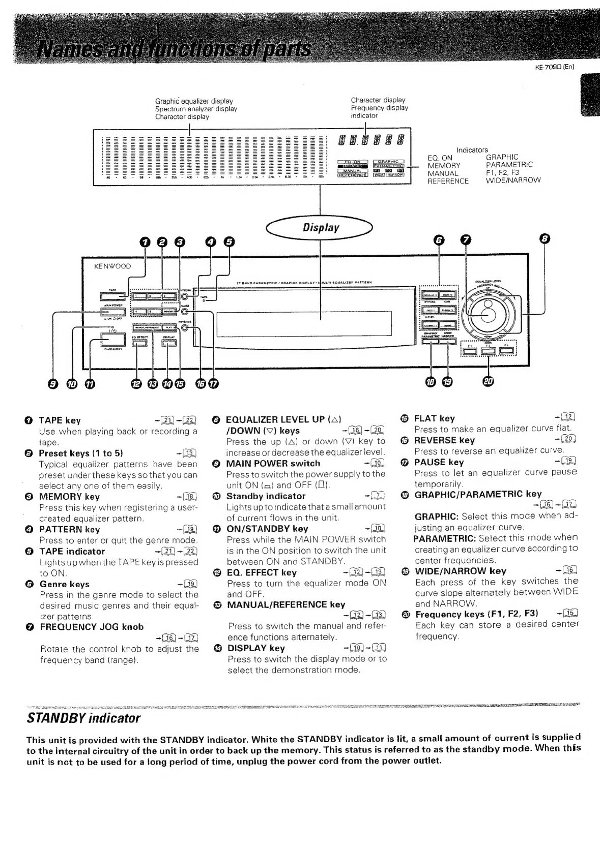
Ack
Navas:
and
danetions
at
ourts
7
Use
of
equalizer
effect
WITH
LAPD
....resssescerescensrecnencertenensneenens
21
PBUES
ieccsescseciuteatiniadesccdssteecssanetstatnn
ten
Applying
equalizer
effect
to
tape
playback
...c...ccccneneoe
7
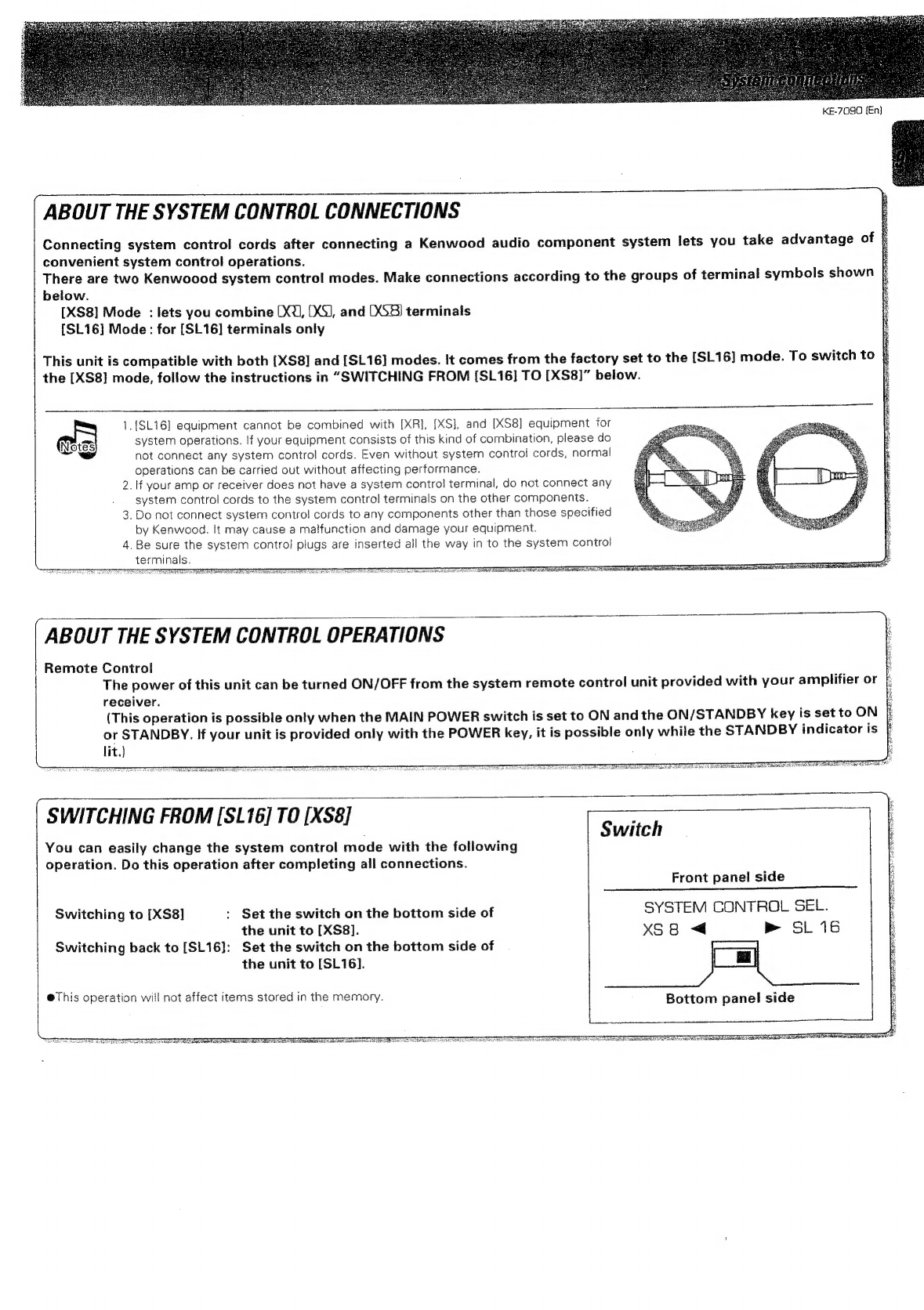
System
connections
Tape
recording
of
sound
with
equalizer
efF@CT
........-.
22
Aone
;
Functions
of
the
graphic
QqQualizer
....sscceereeeeinnin
23
Switching
the
display
modes
Int
Case
Of
CifFICUTtY
.eceesecessesseseessserstecsnsccetsseneneeerectenenstnenes
24
DeMONStaTON
MBIDO
cist
tennsnosmeivdeemimomweuanen
17
AN
Specifications
-.nn.sssssesecscssssssessrsessssorsssosensorsessnesonassnsnstertessneaniees
25
Accessories
Check
that
the
following
accessories
are
present.
Audio
cord
(2)
System
control
cord
(1)
*
AC
plug
adaptor
(1)
*
Use
to
adapt
the
plug
on
the
power
cord
to
the
shape
of
the
wall
outlet.
(Accessory
only
for
regions
where
use
is
necessary.}
4
a