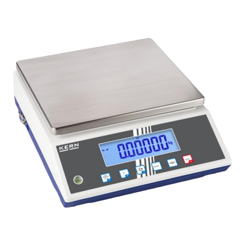
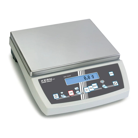
KERN KERN AEJ User manual

KERN & Sohn GmbH
Ziegelei 1
D-72336 Balingen
Tel: +49-[0]7433- 9933-0
Fax: +49-[0]7433-9933-149
Internet: www.kern-sohn.com
Service manual
Analytical balances
KERN AEJ/AES
Version 1.0
4/2009
GB
AEJ/AES-SH-e-0910
1

GB KERN AEJ/AES
Version 1.0 4/2009
Service manual
Analytical balances
Table of Contents
1Basic information.............................................................................................. 3
2Total View........................................................................................................... 4
3Electric/Electronic Construction...................................................................... 5
3.1 Block Diagram ........................................................................................................5
3.2 Whole Wiring...........................................................................................................6
4Troubleshooting................................................................................................ 7
4.1 Troubleshooting Procedure...................................................................................7
4.2 Troubleshooting Table...........................................................................................8
4.3 Primary Check.......................................................................................................10
4.4 Check of Electric/Electronic Parts......................................................................11
5Adjustment and Setting.................................................................................. 13
5.1 Span Calibration (Adjustment with internal weight – AEJ) ..............................13
5.2 Span Calibration (Adjustment with external weight – AES).............................14
5.3 Verification switch and seals ..............................................................................15
5.4 Corner Error Adjustment .....................................................................................16
5.5 Linearity Adjustment............................................................................................17
5.5.1 Linearity Adjustment of AES 120-4 and AEJ 120-4M...................................................... 17
5.5.2 Linearity Adjustment of AES 220-4 and AEJ 220-4M...................................................... 18
5.6 Calibration of Built-In Weight (Ref Cal) – only AEJ...........................................19
5.7 Address Data Check and Re-setting...................................................................20
5.8 Adjustment of Overload Stopper ........................................................................22
6Parts Replacement.......................................................................................... 23
6.1 How to Remove the Case.....................................................................................23
6.2 The Sequence of HT-DP Board Replacement....................................................24
6.3 The Sequence of Mechanical Unit Replacement...............................................26
6.4 The Sequence of Tuning-Fork Sensor................................................................29
7Parts List.......................................................................................................... 30
7.1 Explosion Diagram...............................................................................................30
7.2 Bill of Material.......................................................................................................31
8Appendix.......................................................................................................... 32
2

1 Basic information
Grundlegende Hinweise
The device must be repaired only by trained specialist staff or personnel with
professional formation (such as a repair-specialist accredited by law
concerning verification).
The service manual is obligatory for repair work.
After repair, original conditions of the device have to be restored.
Only original spare parts should be used.
Instructions about conformity-evaluated scales:
Repair must be carried only at 100% compliance with the type approval.
A violation of this specification will result in a loss of the type approval!
After successful repair the balance will have to be reverified before it can be
used again in a statutorily regulated field.
Das Gerät darf nur von geschultem oder beruflich ausgebildetem
Fachpersonal (z. B. eichrechtlich anerkannter Instandsetzer) repariert werden.
Die Serviceanleitung ist bindend für Reparaturen.
Das Gerät muss nach erfolgter Reparatur wieder in den Originalzustand
zurückversetzt werden.
Es dürfen nur Originalersatzteile verwendet werden.
Hinweis zu konformitätsbewerteten Waagen:
Reparatur darf nur in 100% -iger Übereinstimmung mit der
Bauartzulassung erfolgen. Ein Verstoß gegen diese Vorgabe führt zum Erlöschen
der Bauartzulassung!
Nach erfolgreicher Reparatur muss eine Nacheichung erfolgen, um die Waage
wieder im gesetzlich geregelten Bereich verwenden zu können.
3

2 Total View
Windshield
Weighing plate
Protection ring
Air bubble
LCD display
RS 232 interface Printer interface
Connection mains adapter
Foot screw
Underfloor
weighing device
Foot
4

3 Electric/Electronic Construction
3.1 Block Diagram
Calibration Weight Unit
(AEJ only)
PRINT
5

3.2 Whole Wiring
Calibration Weight Unit
(AEJ only)
PRINT
6

4 Troubleshooting
4.1 Troubleshooting Procedure
7

4.2 Troubleshooting Table
SYMPTOMS CAUSES & REMEDY
No display lights on. 1. HT-DP board is defective.
2. AC adaptor is defective.
3. Inner connecting cord is not properly connected.
[
u - Err ] or
[
o - Err ] appears
on the display.
1. Wrong weighing pan is applied.
2. Tuning-fork sensor or mechanical unit is
defective.
3. HT-DP board is defective.
4. Setting of address data has mistake.
5. Coefficient memories (address data) have
changed by noise or static electricity. Re-set the
address data and/or adjust the linearity.
Display does not get settled down.
Display does not repeat correctly.
Zero point drifts.
1. Some parts such as stopper touch others.
2. Weighing pan touch other parts.
3. Foreign substances are in the scale.
4. Tuning-fork sensor or mechanical unit is
defective.
5. Affected by wind or disturbing oscillation.
[
o - Err ]
appears
with
net
load
less
than
full
capacity.
1. Gross weight applied to the scale pan (net weight
+ tare value) exceeds the scale capacity.
2. Setting of address data has mistake.
3. Coefficient memories (address data) have
changed by noise or static electricity. Re-set the
address data and/or adjust the linearity.
4. Wrong external weight is used in the span
calibration.
Span error is too much. 1. Tuning-fork sensor or mechanical unit is
defective.
2. HT-DP board is defective.
3. Setting of address data has mistake.
4. Coefficient memories (address data) have
changed by noise or static electricity. Re-set the
address data and/or adjust the linearity.
Non-linearity is too much. 1. Tuning-fork sensor or mechanical unit is
defective.
2. Setting of address data has mistake.
3. Coefficient memories (address data) have
changed by noises or static electricity. Re-set the
address data and/or adjust the linearity.
4. Wrong external weight is used in span
calibration.
8

SYMPTOMS CAUSES & REMEDY
Corner Error is too much. 1. Mechanical unit is defective. Leaf spring is bent
or twisted.
2. Pan base touch other parts.
Display suddenly disappeared. 1. HT-DP board is defective.
2. AC adaptor is defective.
or
appears.
1. HT-DP board is defective.
2. Coefficient memories (address data) have
changed by noises or static electricity. Re-set the
address data and/or adjust the linearity.
appears. 1. The weight of reference sample is too light (%
mode, counting mode).
appears. 1. Wrong external weight is used in span calibration
(external weight must be more than 50% of
scale capacity).
appears. 1. Span error exceeds 1% of scale capacity in
span calibration. Check the external weight.
appears. 1. During calibration there was a weight on the
weighing plate. Remove it from the pan.
appears. 1. Span error exceeds 1% of capacity in automatic
span calibration.
appears. 1. Interval time is not properly set.
appears. 1. Internal clock is defective. Check internal clock
and replace HT-DP board, if necessary.
[
r - Err ] appears. 1. The weight error exceeds ±100.00mg. Re-set the
weight error within ±100.00mg
[
A - Err ] appears. 1. Internal calibration automatics defective
appears. 1. Wrong operation in Cumulate Function or Net
Addition Function.
9

4.3 Primary Check
1. Is there any wind around the site? Is there any oscillation?
2. Is anything under the pan base or the weighing pan?
balance nor under pan/pan base.
When you attach or remove pan,
pan base, windshield, take care no
dust and/or liquid gets into the
Pan base
Pan
3. Is the weighing pan the right one?
4. Is the windshield properly attached?
5. Is the working table stable?
6. Is the balance installed in level?
Position of the air
bubble in the level
Adjuster
7. Is the AC adaptor properly connected both with scale and with outlet?
AC adapter connector
10

4.4 Check of Electric/Electronic Parts
1. Check of HT-DP board
11

2. Check of input voltage
TP0 – CN1-1 +9V~ +14V
3. Power voltage in the circuit
TP0 – TP1 +4.75V~ +5.25V
TP0 – TP2 +3.15V~ +3.45V
TP0 – IC12-O +7.6V~ +8.4V
TP0 – IC13-OUT +2.65V~ +2.95V
TP0 – D3 kasode +2.0V~ +2.4V
TP0 – IC8-5 -8.4V~ -7.6V
4. Check of signal wave
TP0 – IC1-39 (19.968MHz)
TP0 – TP4 (38.4MHz)
Check of tuning-fork vibration (800~1000Hz)
CH1: TP0 – TP6 P-P 200mv or more
CH2: TP0 – TP5 P-P 9V or more
12

5 Adjustment and Setting
5.1 Span Calibration (Adjustment with internal weight – AEJ)
Procedure for adjustment (according to the operating instructions):
Observe stable environment conditions. A warming-up time of approx. 8 hours for
stabilisation is necessary.
Function menu 1 setting: [ ]
x CA. 1
ÖPress the CAL key
AWT. CAL
CAL
PWSH C
CAL
ÖPress the CAL-key again and adjustment will take
place automatically.
AWT. CAL
CAL
CH. O
1
CAL
CH. F.S.
1
CAL
ÖThe process of adjustment is completed.
Adjustment protocols will be issued automatically
if you connect an optional printer, see chpt. 15
“printer mode”. Whilst printing is in progress [busy
] will be displayed.
EnD
CAL
ÖThe balance returns automatically into weighing
mode.
13

5.2 Span Calibration (Adjustment with external weight – AES)
Procedure for adjustment (according to the operating instructions):
Observe stable environment conditions. A warming-up time of approx. 8 hours for
stabilisation is necessary.
Function menu 1 setting:
x CA. 3
Recommended adjustment weight:
AES 120-4: 100g (E1) AES 220-4: 200g (E1)
ÖPress the CAL key
EHT.CAL
CAL
1K
PWSH C
CAL
ÖPress the CAL-key again; zero point will be
saved.
EHT.CAL
CAL
1K
Qn. O
CAL
ÖWhen display [on F.5]appears, put the adjusting
weight carefully in the centre of the weighing pan.
CAL
Qn
F.5.
ÖThe adjustment process is started
CAL
Qn
F.5.
ÖThe process of adjustment is completed.
Adjustment protocols will be issued automatically
if you connect an optional printer, see operating
instructions. Whilst printing is in progress
[busy ] will be displayed.
BWSX
CAL
EnD
CAL
ÖThe balance returns automatically into weighing
mode.
Take away adjustment weight.
14

5.3 Verification switch and seals
Prior to verification you will have move the calibration switch to verification position
(See direction of arrow, fig. 1). In this position the display shows a bracket around the
last display point.
After verification the balance is sealed at the indicated positions.
Seal of approval Seal of approval
Fig. 1
Move verification switch to
verification position.
Seal/rubber plug/verification switch
Access to the verification switch is achieved
by removing the possibly existing seal (veri-
fication becomes invalid) and the rubber
plug.
Position of
verification switch Status
forwards
Balance is unlocked for the adjustment process, ad-
justment will be possible "ADJ" appears when the bal-
ance is switched on.
backwards Verification position - Adjustment locked
15

5.4 Corner Error Adjustment
1. Turn the adjusting legs to bring the bubble of the level to the center of the
circle.
2. Put the full scale weight at “A” and push TARE key.
3. Move the weight to Band C. To adjust bolts Rand Lreferring to the table
below so that the corner error is within the specified range.
基準点
C A
+
<corner error adjustment table> B
+: Error is positive to the center
-: Error is n egative to the center
Drive the bolt clockwise
Drive the bolt counter-clockwise
Bolt L Bolt R
Display
A
B
C
L R
+
-
Displ ay
A
B
C
L R
--
Displ ay
A
B
C
L R
-+
Displ ay
A
B
C
L R
++
16

5.5 Linearity Adjustment
Set the verification switch to unlocked before doing the linearity adjustment (see
chapter 5.3).
Prior to verification, the verification switch must be moved into the verification
position.
5.5.1 Linearity Adjustment of AES 120-4 and AEJ 120-4M
1. While pressing both + , press to switch on the balance.
Release both keys when [ Ht00x ] appears (maintenance mode).
2. After a while, display changes to weight value (not the zero point).
Press until appears after displaying .
3. While pressing first, press together and release both.
4. starts blinking to indicate zero adjustment is performed
automatically.
5. When display changes to blinking, put the external weight on
the pan according to the table below ( ~ ).
6. When display appears , press key. The display changes to
and returns to normal weighing mode.
AES / AEJ – 120g
additional loaded weight
(accumulated load)
0g (0g)
30g (30g)
30g (60g)
30g (90g)
30g (120g)
17

5.5.2 Linearity Adjustment of AES 220-4 and AEJ 220-4M
1. While pressing both + , press to switch on the balance.
Release both keys when [ Ht00x ] appears (maintenance mode).
2. After a while, display changes to weight value (not the zero point).
Press until appears after displaying .
3. While pressing first, press together and keep pressing both.
When appears, release both keys.
4. While pressing first, press together and release both.
5. starts blinking to indicate zero adjustment is performed
automatically.
6. When appears, put the external weight of 100g on weigh-
ing pan. The display changes to , put additional 120g (220g
in accumulate) on weighing pan.
7. appears again. Remove 120g (100g remains on the pan).
The display changes to . Remove 100g (nothing on the pan).
8. When display changes to blinking, put the external weight on
the pan according to the table below ( ~ ).
9. The display changes to and returns to normal weighing mode.
AES / AEJ – 220g
additional loaded weight
(accumulated load)
0g (0g)
50g (50g)
50g (100g)
50g (150g)
50g (200g)
20g (220g)
18

5.6 Calibration of Built-In Weight (Ref Cal) – only AEJ
1. Hold key while key is pressed until [FWnm 2]is displayed
(function menu 2). Release both keys.
Set and press the key to display
2. While pressing first, press together and release both. After
a while starts blinking.
3. When appears, put the external weight of full capacity on
weighing pan (max. 120g= 120g / max. 220g= 220g).
4. starts blinking. The display changes to after
displaying .
5. Remove external weight from the pan.
6. The display changes .
When internal calibration is successfully completed, appears
on the display.
7. Press key to return to normal weighing mode.
19

5.7 Address Data Check and Re-setting
a. Why do you need to re-set the address data, and in which case?
“Address data” (coefficient memories) sometimes changes by noise in the
environment or by static electricity. You can re-set the address data so as to bring back
the balance to the initial factory condition.
Re-set
address data
Span
Address data
(coefficient memories)
changed
Calibration
Primary
Check
You can find the address data sheet on the bottom of the balance.
data sheet
How to read the address data sheet
S=81S073 P=AJ0004 3003
00-9A,57,41,98,22,12,9B,32
08-85,19,30,00,27,56,62,80
10-00,18,27,39,26,72,17,12
18-99,72,27,8D,49,27,61,48
20-84,33,77,69,92,20,20,00
28-00,00,20,10,00,00,00,0A
30-06,07,02,0B,07,00,00,FF
38-1C,0B,14,53,0A,00,00,00
40-00,00,00,00,00,00,00,00
48-00,00,5F
左からAdr.00 ~ 07
左からAdr.08 ~ 0F
左からAdr.10 ~ 17
左からAdr.18 ~ 1F
左からAdr.20 ~ 27
左からAdr.28 ~ 2F
左からAdr.30 ~ 37
左からAdr.38 ~ 3F
左からAdr.40 ~ 47
左からAdr.48 ~ 4A
音叉番号 プログラム 番 号
Number of
(see 5-1 / 5-2) (see 4-3)
From left to right : Add. 00~07
From left to right : Add. 48~4A
From left to right : Add. 40~47
From left to right : Add. 38~3F
From left to right : Add. 28~2F
From left to right : Add. 30~37
From left to right : Add. 18~1F
From left to right : Add. 20~27
From left to right : Add. 08~0F
From left to right : Add. 10~17
Tuning fork
Program number
20
This manual suits for next models
1
Table of contents
Other KERN Scale manuals