Kernel Flow 50 User manual


Table of Contents
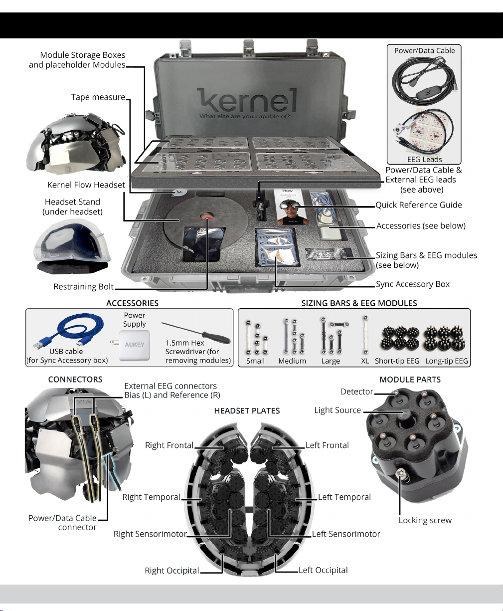
WHAT’S IN THE BOX..................................................1
BEFORE YOU BEGIN..................................................3
Unpacking Kernel Flow........................................3
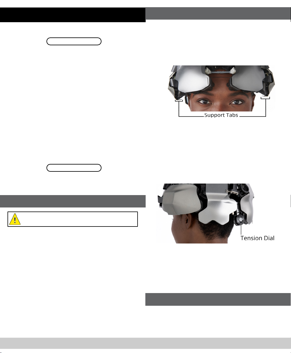
Handling the Headset..........................................4
Using EEG..............................................................4
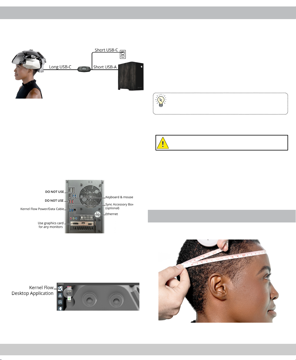
STEP 1: CONNECT THE HEADSET TO THE PC.........5
STEP 2: INITIALIZE THE HEADSET ............................6
STEP 3: MEASURE PARTICIPANT’S HEAD ................6
STEP 4: INSTALL THE SIZING BARS..........................7
STEP 5: PLACE THE HEADSET...................................7
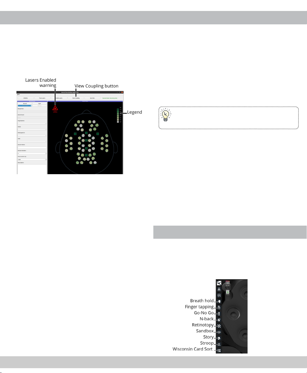
STEP 6: TUNE THE LASERS .......................................8
STEP 7: CHECK THE SCALP COUPLING ...................9
STEP 8: RECORD A SESSION.................................. 10
STEP 9: PERFORM A TASK...................................... 10
STEP 10: END THE SESSION .................................. 11
STEP 11: VIEW OR DOWNLOAD YOUR DATA ...... 12
LASER SAFETY
Kernel Flow complies with Federal Laser Product Performance
Standards (FLPPS) 21CFR1040.10 as a Class 2 laser product. A
Class 2 laser means any laser product that permits human access
to levels of laser radiation in excess of Class 1 accessible emission
limits (AEL) during normal operation. During normal operation
the Kernel Flow emits invisible (850 nm) Class 1 laser radiation
and visible (690 nm) Class 2 laser radiation. Kernel Flow utilizes 52
Class 1 diode lasers and 52 Class 2 diode lasers.
A Class 1 laser is considered to be
incapable of producing damaging
radiation levels during operation and
exempt from any control measures.
A Class 2 laser system emits in the
visible portion of the spectrum
(400 nm to 700 nm) and eye pro-
tection is normally aorded by the
aversion response. The aversion
response is dened as closure of
the eyelid, eye movement, pupillary
constriction, or movement of the
head to avoid an exposure to a noxious or bright light stimu-
lant. The aversion response to an exposure from a bright, visible,
laser source is assumed to limit the exposure of a specic retinal
area to 0.25 s or less.
IMPORTANT Kernel Flow is designed to be positioned on the
user prior to activation. Users should not intentionally stare
into/or at the visible red beams.
CAUTION Use of controls or adjustments or performance of
procedures other than those specied herein may result in
hazardous radiation exposure.
DEVICE IS NOT USER-SERVICEABLE Do not open or attempt to
service modules. Modules must be returned to manufacturer
for service or repair.
IMPORTANT Kernel Flow has not been evaluated for clinical
performance or use, accuracy, reliability, or eectiveness, and
has not been validated for any particular use.
FOR RESEARCH USE ONLY Not intended for use in the
diagnosis of disease or other conditions or in the cure,
mitigation, treatment, or prevention of disease.
Kernel Flow 50 is a pre-production prototype that currently has
not been tested for electrical safety, electromagnetic compati-
bility, or biocompatibility.
Any misuse or mishandling of the product, including failure to
properly clean and store the product, will void the warranty.

WHAT’S IN THE BOX
2
1

BEFORE YOU BEGIN
Before using Kernel Flow for the rst time, you must
set up your organization using the Researcher Portal:
portal.kernel.com
Refer to your purchase conrmation email to conrm
your primary user account login information. Use this
web-based portal to perform the following tasks:
• Add researchers to your team
• Create studies
• Create participant IDs
• Generate participant invitation codes
• Create task names
• Upload surveys for study participants
• View, analyze, and download study data
NOTE: Before beginning the steps in this guide, you
must, at a minimum, create a study and one partic-
ipant ID, and the intended participant must accept
the invite code (in the Kernel App on iOS or Android)
granting permission for their data to be viewed.
Detailed instructions for all these tasks are available at:
docs.kernel.com
Once you’re ready to begin, follow the steps in this
guide to connect, prepare, and congure your Flow
headset and to record your rst session.
Unpacking Kernel Flow
IMPORTANT: Before proceeding, review the
safety warnings on the rst page of this booklet.
Kernel Flow is shipped with specialized protective
packaging. Upon unpacking, be sure to preserve
and save these materials so the device can be safely
moved or shipped in the future.
1. Remove the foam tray containing the Module
Storage Boxes and set it aside.
2. Remove the Instapak foam insert covering the
headset. Do not discard this.
3. Take the Flow headset out of the case. This
wrapped package contains the headset as well
as the headset stand.
4. Remove the anti-static bag covering the headset.
5. Unscrew and remove the red Restraining Bolt
that holds the headset to the stand.
Handling the Headset
• When you remove the headset from the case,
remove the Headset Stand with it.
• Whenever possible, use the headset stand.
• Always use the at Support Tabs (under the
Temporal plates) to lift or carry the device.
• Never lift or hold the headset by the hinges on
the top or by a single plate.
The headset should always be kept tightly tensioned.
Loosening should only be done temporarily to get the
device on and o the stand or a participant’s head.
Even while moving the headset from one support
element to another, tightening keeps the plates from
excessive movement which can damage the device.
• To tighten, turn the Tension Dial clockwise until
it is snug.
• To loosen, turn the Tension Dial a half-turn
counterclockwise to release the tension, then
gently pull the plates apart as needed to t the
device on or o of a support element.
Using EEG
This guide does not include instructions for using the
EEG modules.
To learn about installing and using the provided EEG
modules, visit docs.kernel.com/docs/eeg.
4
3

STEP 1: CONNECT THE HEADSET TO THE PC
Kernel Flow must be connected to the provided PC
to be congured and controlled. Follow the following
steps and diagrams to ensure successful operation.
1. Plug the long USB-C end of the Power/Data
Cable into the USB-C connector on the back of
the headset.
2. Plug the shorter USB-C end of the Power/Data
Cable into the Kernel Flow Power Supply.
3. Plug the Power Supply into the same outlet or
power strip as the Kernel Flow Conguration PC.
4. Plug the USB-A end of the Power/Data Cable into
the PC (Do not use the red USB ports).
The Flow device is now powered on.
NOTE: Even though a blue light illuminates on the
headset, all lasers remain o until they are enabled
using the Kernel Flow Desktop Application.
5. Turn on the PC and launch the Kernel Flow
Desktop Application (the rst icon in the Taskbar
as illustrated in the picture below).
NOTE: Your PC has been pre-congured by the
Kernel team prior to shipment so it is ready to
operate the Flow headset immediately. No login or
setup is required to run the Kernel Flow Application.
STEP 2: INITIALIZE THE HEADSET
1. Be sure the headset is seated and tightened on
the Headset Stand.
2. In the main window of the Kernel Flow desktop
application, click Initialize.
3. A conrmation dialog appears. Click Initialize to
proceed.
Initialization performs a series of tests and pro-
cedures to ensure all modules are synchronized
and receiving adequate signal.
TIP: You may disregard the color of the modules
onscreen because the headset is not recording
brain activity at this stage in the setup process.
4. When Initialization is complete, click Close to exit
the Initialization window.
IMPORTANT: Initialization must be performed
every time the headset is powered on.
NOTE: Kernel Flow’s lasers benet from a warm up
period prior to recording a study. Often the process
of tuning and prepping a participant (while lasers
are enabled) provides sucient warm-up time,
but you may consider enabling the lasers for 5-10
minutes while the headset is sitting on the Headset
Stand after Initialization. Just be sure to disable the
lasers prior to removing the Headset after this step.
STEP 3: MEASURE PARTICIPANT’S HEAD
1. Wrap the supplied tape measure around the
participant’s head as illustrated below.
2. Ensure the tape measure is snug and free of kinks
or twists and note the number of centimeters.
6
5

STEP 4: INSTALL THE SIZING BARS
1. Using the table below, select the size of Sizing
Bars best suited for the current participant.
Sizing Bar Measurement Chart
Circumference 52-54cm 55-57cm 58-60cm
Sizing Bars S (White) M (Gray) L (Black)
TIP: Sizing Bars may be mixed to nd the best
possible t. Notate the bars selected and use the
same set every time that participant is recorded.
2. Turn the headset upside down and place it onto
the inverted protective foam insert from the ship-
ping case, tightening and loosening as described
in the Handling the Headset section above.
3. Insert the four Sizing Bars, using the magnets
to snap the bars into the proper position as
illustrated in the diagram below.
TIP: You may need to loosen the Tension Dial in
order to install the Top Sizing Bar.
STEP 5: PLACE THE HEADSET
1. Loosen the Tension Dial, then, holding the device
by the Support Tabs, gently set the headset on
the participant’s head.
2. Using two hands, carefully adjust the headset so
the Alignment Guides on each side of the device
align to matching positions on each side of the
head.
3. Adjust the headset so the Alignment Guides on
the front of the device are positioned symmetrical-
ly above the eyes.
TIP: You may need to rotate the headset forward
towards the brow for proper alignment.
4. Tighten the Tension Dial so the headset is as snug
as possible while still remaining comfortable for
the participant.
STEP 6: TUNE THE LASERS
Once the headset is seated on the participant’s head,
you must tune the lasers. This operation turns on the la-
sers and congures the strength of each laser to ensure
every detector is receiving an adequately strong signal.
NOTE: The Tune Lasers tool must be re-run each time
the headset is placed on a participant’s head.
1. In the Kernel Flow application, at the top of the
main window, click the Tune Lasers button.
2. Click Tune Lasers in the window that appears.
A progress bar appears to indicate the duration of
the operation.
3. Once the operation is complete, click Close to
close the Tune Lasers window.
NOTE: When the Tune Lasers command is complete
the lasers remain enabled.
SAFETY WARNING: Never remove headset from
the participant’s head while lasers are enabled.
8
7

STEP 7: CHECK THE SCALP COUPLING
The Module Status View displays the quality of signal
received by each detector, and in aggregate by each
module.
The legend indicates the signal quality that each color
represents; darker green means a better signal.
By default, the Module Status View uses the total
count of photons received to determine the quality of
the data for each detector.
At any point you can click View Coupling to switch
the view to display in SCI (scalp coupling index) values
rather than total counts. There will be a ve-second
delay before the view updates.
Click View Total Counts to switch back.
If the Module Status View indicates modules with
insucient signal, rst switch to Total Counts, then
try the actions below to improve the connection:
• Verify that you have the most appropriately
sized Sizing Bars installed, and that the Tension
Dial is properly tightened.
• Attempt to move thick locks of hair out of the
way of the aected module(s).
• Gently manipulate or wiggle the headset.
• Re-run the Tune Lasers command.
• For additional troubleshooting instructions,
visit docs.kernel.com.
STEP 8: RECORD A SESSION
NOTE: Remember that participants must explicitly
provide consent by accepting a participant Invita-
tion Code before their session data may be viewed,
downloaded, or analyzed.
1. In the Kernel Flow Desktop Application, click the
Login button (if you haven’t already).
2. Enter your Kernel Cloud ID (email address) and
password and click Login or press Enter.
Once logged in, your organization and available
Studies are loaded into the software.
TIP: Kernel Flow can be operated oine (without
an Internet connection). Instructions are available
at docs.kernel.com.
3. Choose a Study, Participant ID and optionally
enter other metadata (such as a Task name,
Session name, which Sizing Bars are used, or
other notes) to save with the session.
4. Optionally change the value in the Maximum
Duration eld. Enter in seconds (for example:
10 minutes = 600).
5. Click Record.
6. Conrm that the participant wearing the headset
is correctly associated with the Participant ID
displayed onscreen, and click Continue.
The system begins recording.
STEP 9: PERFORM A TASK
Kernel provides a collection of standardized tasks
to aid in your data collection. These tasks are pre-
installed on the Kernel Flow PC. Each task is
represented by an icon in the Taskbar.
For a description of each task, go to docs.kernel.com.
10
9

1. Click an icon in the Taskbar to open a Task.
The Task Parameters dialog opens.
TIP: For a simple, short example that should
generate a robust response, choose Breath Hold.
2. Optionally customize the settings, then click OK.
Each task includes a Home screen with buttons
to display instructions, run in practice mode, run
the actual task, and to exit the task.
NOTE: Some tasks do not include a practice mode.
TIP: While running the task, be sure to move the
pointer away from the onscreen stimuli. Also, be
careful not to click outside the Task window while
a task is running, or keyboard inputs won’t be logged.
NOTE: Your Kernel Flow system includes a Sync
Accessory Box for connecting external stimuli or
external data-recording devices. Instructions for the
Sync Accessory Box can be found at docs.kernel.com.
STEP 10: END THE SESSION
A session ends when the maximum duration elapses,
or the researcher clicks the Stop Recording button.
All captured data is automatically uploaded to Kernel
Cloud for processing and analysis.
• If you want to immediately begin another session
with the same participant, repeat step 9 above.
• If you are done recording sessions, there are
important steps to follow:
1. If necessary, click the Stop Recording button.
2. Click Disable Lasers.
SAFETY WARNING: Never remove the headset
from a participant while the lasers are enabled.
3. Loosen the Tension Dial and gently spread
the plates apart, then, lifting from the Support
Tabs, carefully remove the headset from the
participant. Avoid lifting by the top hinge.
NOTE: The exterior of the headset may be hot after
recording.
4. Tighten the Tension Dial again and cradling the
headset upside-down in your lap, remove and
stow the Sizing Bars.
5. Loosen the Tension Dial, and place the head-
set back on the Headset Stand, then tighten
the Tension Dial again.
6. Disconnect and stow the Power/Data Cable.
Full instructions for storage and cleaning of the
headset can be found at docs.kernel.com.
STEP 11: VIEW OR DOWNLOAD YOUR DATA
1. When you’re ready to view or download the data
captured during your session, login to the Kernel
Cloud Researcher Portal at portal.kernel.com.
2. Click the study you selected in Step 8 above.
3. Click Datasets and you’ll see a list of sessions (or
datasets).
4. Click the dataset from the list to open the detail
page for the recording you just made.
5. Click Pipelines to access a Quality Control (QC)
le describing the data, or you can generate and
download a SNIRF or NIfTI le containing the data.
NOTE: The Kernel Flow system includes many
additional tools and features not covered in this
guide. Also, this guide may be updated. Please
check the website (link below) for the latest version
of this document, as well as for the full user guide.
docs.kernel.com
12
11

© 2021 Kernel
090821-01
Table of contents
Other Kernel Medical Equipment manuals
Popular Medical Equipment manuals by other brands

ADC
ADC ADSCOPE Series Use, care & maintenance

Invacare
Invacare BARTRAP owner's manual

Freedom Showers
Freedom Showers LIFESTYLE & WELLNESS Silhouette Comfort Plus installation instructions

EzYCheckPro
EzYCheckPro EZY302 Quick operator's guide

Stryker
Stryker POWER PRO TL Operation & maintenance manual

Cardioline
Cardioline AR 600 Technical & service manual