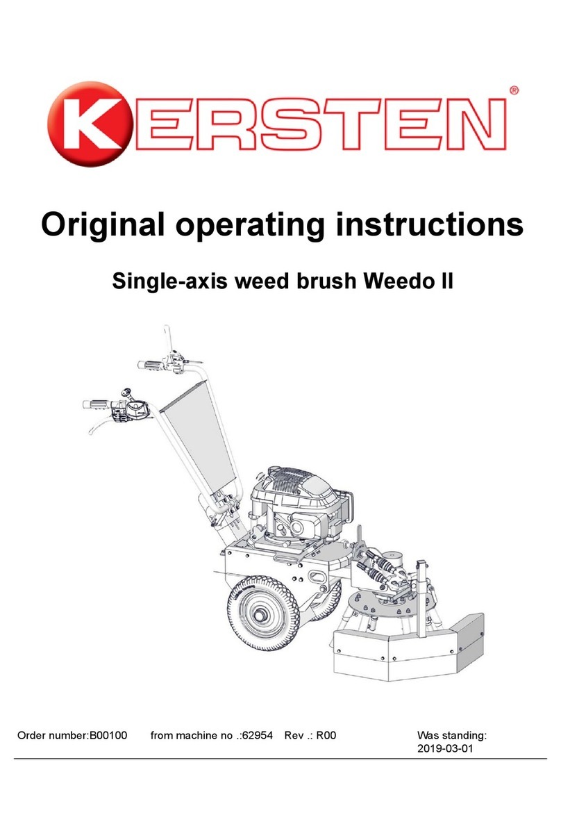
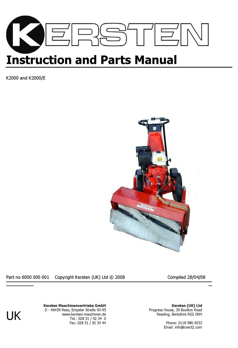
Kersten WeeDo User manual

Operating
Instructions for
WeeDo
Kersten Arealmaschinen GmbH
Empeler Straße 95
D - 46459 Rees
www.kersten-maschinen.de
Order Number: B00066 From Machine .- Nr.: 55732 Rev.: R00 From: 30.07.2015
Kersten (UK Ltd Tel. 01189869253
Progrees House
39 Boulton Road Reading RG2 0NH
www.kerstenuk.com
Manufactured by Distributed in UK by

2
English
1Forwards......................................................................................................5
2About this Instrucon Manual.....................................................................6
2.1 Before Operang..............................................................................6
2.2 Notes on Using this Instrucon Manual...........................................6
3Safety Instrucons........................................................................................7
3.1 General.............................................................................................7
3.2 Intended Use....................................................................................7
3.3 General Safety and Accident Prevenon Procedures......................7
3.4 Used Pictograms.............................................................................12
4Disposal......................................................................................................13
5Guarantee..................................................................................................13
6Descripon................................................................................... .............14
6.1 General Descripon.......................................................................14
7Inial Assembly..........................................................................................14
8Operaon...................................................................... ............................14
8.1 Combuson Engine Starng...........................................................14
8.2 Starng O.....................................................................................14
8.3 Adjusng the Brush Head..............................................................15
8.4 Adjusng the Guard.......................................................................15
9Maintenance...............................................................................................16
9.1 General...........................................................................................16
9.2 Daily Maintenance.........................................................................16
9.3 Maintenance aer 20 hours or longer Idle Time...........................16
9.4 Changing Brush Secons................................................................16
9.5 Maintenance aer 100 Hours of Operaon...................................17
9.6 Storage...........................................................................................17
10 Technical Data............................................................................................18
11 EC Cercate of Conformity.......................................................................19
12 Diagram and Replacement Brush Parts......................................................20
Contents

3
K
L

4

5
1Introducon
Dear Customer,
Thank you for choosing a quality product from the company Kersten.
This product is designed and produced using the most modern manufacturing
techniques and extensive quality assurance measures.
It is only when you are sased with your product that our goal is achieved.
Before the rst use of this machine or aachment, please read this manual
fully and conscienously. Please ensure all operators of this machine and any
aachments also read this informaon.
Keep this document handy for future reference.
Only by referring to this manual can you operate this machine safely and
eecvely.
We wish you every success with your Kersten Machine.
Dipl.-Ing. (FH) Robert Bosch
Managing Director

6
2About This Manual
The machines described in this manual are subject connual to technical proress. All
informaon/pictures and technical data in this manual correspond to the latest
specicaons at the me of publicaon. The manufacturers reserve the right to make
alteraons at any me. Please ensure the technical informaon
2.1 Before Operang
Before you start the engine or aempt to aach or operate any machine, we ask that
you urgently to make yourself familiar with the manual and the operaon of the
machine.
If you are in any doubt over any operaon or require further details, you should contact
the supplier, importer or manufacturer of this product.
It is mandatory that all users of this product are familiar with this manual and the
product.
You should rst make yourself familiar with the machine at a slow speed and on a at,
even surface.
●Read all safety references on the following pages!
●Read the operang instrucons before aaching or start-up!
●Use this manual in conjuncon with the power unit manual if applicable!
Pass all safety instrucons onto other users!
2.2 Notes on using this manual
All points to be considered are indicated as follows: Example
●Text
●Text
Procedural instrucons are indicated as follows: Example
1. Text
2. Text
In this manual images and their components are referenced in various secons . The
images are labelled with numbers 1 , 2 , 3, etc. the components A, B , C , etc. Example:
A reference to component C in gure 2 is Indicated by( 2: C . ) .

7
3.0 Safety Instrucons
It is important to note that not all possibilies can be covered within this manual.
The manual assumes that the operator has a general awareness for Health and
Safety to have been appointed an operator in the rst place.
This machine has been designed, so far as is reasonably praccal, so that it will not
endanger the safety of the operator or anyone else if the machine is used and
maintained according to the instrucons stated in this manual which have been
compiled following research and experience of the manufacturers. In order to
minimise the risk of accidents please consider the following informaon.
3.1 General
This symbol indicates WARNING. Failure to follow the instrucons could
result in personal injury and/or damage to property.
Before starng or using this machine or aachment carefully read these
operang instrucons and safety regulaons in this instrucon manual.
3.2 Intended use
This is a single axle machine incorporates a Weedbrush for the loosening or
removal of weeds and debris and detritus from hard surfaces commonly
found in agriculture , horculture, amenity, facilies management. All other
uses will be considered improper use of the machine
Use going beyond that described is not considered as intended. Therefore
the manufacturer is not responsible for any resulng damage or harm and
the operator alone is responsible for the risk.
Compliance with and adherence to the operang, maintenance and repair
as prescribed by the manufacturer in this manual must be considered
essenal elements of intended use.
The machine may only be operated, repaired and serviced by persons
familiar with the machine, this manual and all relevant safety features and
dangers.
The relevant rules for the prevenon of accidents as well as other safety
relevant rules according to the health and safety at work act must be
considered as part of the operang procedure.
The manufacturer is not liable for any accidents or damage resulng from
modicaons or alteraons carried out on the machine without the express
wrien permission of the manufacturer.
Unauthorised modicaons to the machine will void the manufacturers
warranty

8
3.3 General Health and Safety and Accident Prevenon Regulaons
3.3.1 Basic Principles
●Follow general operang instrucons and all other generally applicable
health and safety regulaons!
This machine should not be operated by any person under the age of 16, not
even under adult supervision. Minors must not be allowed to play with the
machine. Only trained adults may use this machine.
This machine may be subject to regulaons when used on or near the public
highway. This machine is not approved for public transport .
Beware of rotang parts. Keep a safe distance . Placing hands or other parts
of your body in rotang parts may result in severe injuries
Beware of trailing machines and machines with inera. Ensure they stop
completely before making any adjustments.
Operators are advised to wear suitable clothing that is close ng with stout
footwear– safety boots. Loose ed clothes or casual footwear increase risk
of accident.
Do not leave the engine running in an enclosed area.
Be aware that the handling, steering and braking ability of power units
machine may be aected by dierent aachments, when loading/unloading
and when using on gradients.
Do not change manufacturers fast idle speed. Too high speed increases the
risk of accidents.
Unauthorized alteraons, which compromise the reliability, safety or
operaon of the machine are prohibited!
Always inspect the machine prior to use.
3.3.2 Operang and Danger Area
The operator is responsible and liable for 3rd pares within the working area.
Standing in the danger area of the machine is forbidden! Exclude all persons
from the danger area before and during use. Danger is a 10 metre radius of
the machine.

9
Unauthorized alteraons, which compromise the reliability, safety or operaon
of the machine are prohibited!
Always inspect the machine prior to use.
3.3.2 Operang and Danger Area
The operator is responsible and liable for 3rd pares within the working area.
Standing in the danger area of the machine is forbidden! Exclude all persons
from the danger area before and during use. Danger is a 10 metre radius of
the machine. Pay parcular aenon to children and animals which may
enter the working area without warning.
Before starng or restarng the machines ensure the working area has been
cleared of any foreign bodies which could be damaged or cause damage if
hit or thrown by the machine.
When working in public areas the working area should be isolated with a
barrier and indicated with hazard labels to draw 3rd pares aenon to the
potenal hazard. Furthermore the machine should be operated in such a way
that it minimises risks to 3rd pares.
Due to the risks associated with thrown objects from this machine the
wearing of goggles is required during operaon. The approved protecve
goggles for this case must meet the following standards. ANSI Z87.1 for use in
USA and EN 166 for use in European countries.
3.3.3 Before Starng Work
Before starng operang this machine you should be familiar with all
controls and their funcons. Familiarizaon should not be carried out
during operaon. It is too late!
Before starng check the machine for safe operaon.
Check hydraulic connecons and hoses for leaks and replace them if
necessary.
Never operate the machine with defecve or missing safety devices.
Learn how to stop the engine quickly and safely in the event of an emergency.
3.3.4 Starng the Machine
When starng the machine ensure all drives are switched o
Do not run the engine in enclosed spaces.
Ensure the machine is fully assembled with aachments before starng engine.
Do not use baery jumper leads and starng assist uid at the same me as
this could result in explosion.

10
3.3.5 During Operaon
When people, animals, vehicles etc approach the danger area stop the
machine immediately.
Never leave the operang posion while engine is running.
Only leave the operang posion once the machine has fully come to rest.
Never aempt to make adjustments to the machine during operaon.
The transporng of objects and persons on the machine is forbidden.
Should the machine encounter an obstacle which causes a blockage, switch
the machine o and isolate the engine before aempng to clear the
blockage. Take care when removing foreign objects from the machine as
components may become lodged and could possibly be freed abruptly.
Should the machine become damaged during operaon stop the engine
immediately and repair the damage before further use.
In the event of the machine vibrang extraordinarily stop the machine
immediately. Under no circumstances connue to work unl the cause is
idened and resolved.
3.3.6 Leaving the Machine
When parking the machine, close the fuel tap (if available).
Isolate the engine to prevent unauthorised use by removing the key or
removing the sparkplug lead.
Apply the parking brake (if applicable). Alternavely use wedges to prevent
machine from rolling away.
Never leave the machine unaended with engine running.
3.3.7 Fastenings and Tyres
Before working on the machine ensure it is on level surface with the wheels
chocked to prevent the machine from rolling.
Check wheel nuts regularly for ghtness. Reghten when required.
Regularly check tyre pressure. Cauon over inaon may cause explosion.
Repair work on tyres may only be carried out by specially trained personnel
with the appropriate tools and equipment.
3.3.8 Maintenance, Cleaning and Repair Work
Never aempt to perform maintenance or cleaning on the machine unl has
stopped completely.
Before working on the machine ensure it is on level surface with the wheels
chocked to prevent the machine from rolling and the motor has been isolated
by removing the key or removing sparkplug cap.
Check brush condion and safety devices regularly.

11
Damaged brushes must be replaced.
When changing brushes always use appropriate tools and personal
protecve equipment. eg. gloves and goggles.
Only by using original parts from the manufacturer of the equipment can you
be certain the correct specicaon of the parts is met thus the risk of
accidents is minimised.
Keep machine clean to reduce the risk of re.
Cauon should be used when cleaning the machine with high pressure water
to avoid direcng the jet at vulnerable parts such as turned parts, grease
points, oil seals, wheel hubs etc.
Aer cleaning always grease lubricaon points.
Check moving points for ease of movement. If necessary re-grease.
Following maintenance, ensure all safety equipment is returned to the
correct posion and tested before use.
Before carrying out service to the hydraulic system always ensure the
hydraulic system is not pressurised. Liquids under pressure can penetrate the
skin - Risk of Infecon. In the event of an accident of this type seek medical
advice immediately.
Repairs should only be performed by a specialist.
Check hydraulic lines regularly for damage and aging. Replace if necessary.
All exible hydraulic hoses should be changed every 6 years. The date of
manufacture is stamped on the hose line.
3.3.9 Engine, Fuel and Oil
Never aempt to refuel the machine unl it has stopped completely.
Never refuel in a conned area.
Always take precauons to avoid spillage of fuel by using a suitable device.
Always take care to dispose of waste oils, fuels and lters correctly.

12
3.4 Advice and Warning Pictograms
.
The following pictograms may be found on the machine to indicate use, service,
maintenance and safety advice regarding due care and aenon.
Explanaon of symbols used.
Warning, Before Starng Read the Operang
Instrucons and Conform to Safety Instrucons
Warning, Danger of Crushing Injury
Never remove or open protecon devices whilst engine is running
Refer to Technical notes in the Operators Manual
Lubricaon Point
Warning, Danger of Cung Injury
Only touch machine parts once they have fully come to a standsll
Warning, Danger of air bourn objects traveling at speed.
Powered Machinery - Keep a Safe Distance
Only Operate this Machine when Wearing Eye Protecon

13
4Disposal
.
This device must be disposed of according to the regulaon of the municipality or the
country. All possible parts should be recycled and the remainder disposed of in a
sasfactory manner.
The company Kersten Maschinenvertriebs GmbH or Kersten (UK) Ltd does not take
responsibility of disposal.
5Warranty
The manufacturer guarantees its products for 24 months from the date of delivery.
Parts characterised by faults in materials, mechanical and producons processes will
be replaced free of charge by the manufacturer through its sales and technical
servicing network.
The fault found must be reported to manufacturer and, should the circumstances
require, be appropriately documented with a wrien technical report and/or
photographic material.
The faulty part must be returned to the manufacturer who, aer inspecng it and
verifying that the warranty is applicable, will repair or replace it, taking the necessary
me to do so, without charging for either material or labour.
The cost of transport of the parts covered by warranty shall be borne by the
customer, who may organise it personally or authorise the manufacturer to take care
of transport and charge all expenses to the customer.
The warranty shall be voided in the following cases:
- Obvious absence of maintenance
- Improper use of equipment or interference
- Use of non-original spare parts or unsuitable lubricants
- Operaons carried out by unauthorised personnel
-The manufacturer excludes consumable materials and parts subject to normal wear
and tear from the warranty.
- Any damages caused during transport must be reported immediately to the
transporter; otherwise the warranty shall be voided.
- The warranty does not cover direct or indirect damages caused to persons or
objects by failure of equipment or due to enforced prolonged suspension of its use.
- When applying for repairs under warranty, please indicate:
1-serial and model number of the equipment
2-registraon number
3-date of purchase
4-dealer name
IMPORTANT! Please complete the warranty registraon form enclosed and send it to
address below within 14 days.
Kersten (UK) Ltd,
Progress House
39 Boulton Road
Reading
RG2 0NH or [email protected]

14
6Descripon
6.1 General descripon of WEEDO
The WEEDO consists of a non self propelled power unit with a petrol engine
which powers a hydraulic driven brush for weed and debris removal from
hard surfaces.
The WEEDO is composed of a steel structure supporng control handles,
wheels, a petrol engine and the rotary tool holder (1 : F) to which wire
brushes (1 : H) are aached. The rotaon of the brush propels the unit
forwards and scrapes weeds from the surface towards a laterally mounted
splash guard (1: D)
7Assembly
8Operaon
8.1 Starng the Engine
Open Fuel valve ( Set to on)
To start engine from cold, slide the throle lever (1 : B) fully forwards away
from the stop posion. this is known as the choke posion where the engine
receives an enriched fuel mixture. Pull the starter cord. When the engine
starts return the throle lever slightly towards the stop posion unl it
locates in the rst detented posion. In this posion the engine rotates at its
maximum operang RPM and also the posion where the engine may be
started when warm. During the starng process the lever for the PTO (1 : C)
must not be actuated. Further informaon regarding starng the engine may
be found in the engine manufacturers instrucon manual.
8.2 Driving O
The single axle machine does not have a facility to be self propelled and must
be moved by hand.
It is possible to raise the brushes clear of the ground by pushing down on the
handlebar (1 : A). This will help manoeuvring the machine to the correct
locaon. and enable the brush to be engaged prior to contact with the
surface.
The brush rotor is power driven and engaged by the operaon of pressing
down the actuaon lever ( 1: C). This should be done carefully with the brush
in the slightly raised posion so that it is just clear of the ground to avoid any
unwanted reacons as the brush starts to rotate.
Gently lower the brush in to work and rest on the surface. There will be
some jerky movements as the brushes bite in to the debris on the surface.
Hold the handle bar rmly at all mes. The rotaon of the brush we pull the
wheels to provide forwards travel. The operator must remain alert during this
operaon to guide the machine in the desired direcon and speed.

15
8.3 Seng the Brush Rotor
8.3.1 General
The angle of the WeedBrush head is adjustable on 2 axis.
Figure ( 2 : K ) shows the favoured working area of the brush to provide the
best performance in most cases. Generally speaking it is with the brush to
the right and slightly to the rear.
It has been noced that parcularly good results may be obtained aer
rainfall and damp weather.
The forwards speed is generally determined by the strength of the vegetaon.
8.3.2 Adjusng the Angle of the Brush
The fore/a incline adjustment of the brush plate is via the adjustment screw
(3: G). Before the adjustment may be made the clamping lever (3: J) must
be loosened. Once the desired seng is achieved the clamping lever must be
re-ghtened to lock the posion.
The le an right rotaon of the brush is made by adjusng the screws located
on the right hand side of the brush head unit ( 1 : K ). By loosening the top
and ghtening the boom more pressure is applied to the preferred working
area of the brush. By loosening the boom and ghtening to top less
pressure is applied to the preferred working area of the brush. This
adjustment will also have an impact on the forward progression of the unit.
8.4 Adjusng the Debris Guard
Following any adjustments to the brush angles and in the normal event of
brush wear the height of the debris guard must be checked as it is directly
linked. The guard reduces the possibility of material being thrown from the
machine working area during operaon. Its correct use and seng is
therefore very important.
Under no circumstances should the machine be operated without the
guard in its correct posion.
By loosening clamping lever (4: M), the splash guard (4: D) is adjustable in
height. The rubber ap (4: E) from the splash guard must be in working
posion lightly resng on the oor.

16
9Maintenance
9.1 General
The general safety rules found in secon 3.3.5 must be followed
Engine oil changes must take place at the recommended intervals according
to the manufacturers recommendaons.
Waste oils, fuels and lters must be disposed of separately and properly.
The WeedBrush must be regularly maintained. Failure to comply may result in
damage to the machine , persons or property.
Check all safety devices and parts for correct operaon before every use.
When carrying out repairs, maintenance, cleaning as well as reccaon of a
malfuncon ensure the PTO drive is disengaged and the engine has be
isolated by removing the key or sparkplug cap.
Following any work carried out on the machine , replace all guards and safety
features enrely before tesng and using.
Check all hydraulic connecons following the rst 5 hours of operaon.
Tighten as required. Should a leak sll remain then the following course of
acon should be tried. Ensure the system is depressurised. Loosen the pipe
securing nut around 1 turn, twist the pipe clockwise and anclockwise
around 1/2 turn around 3 mes and then reghten the lock nut. If this
fails to x the leak the seek further help from the supplier. Always use
protecve gloves and goggles when working on the hydraulic system.
9.2 Daily Maintenance .
Before each use check the hydraulic oil level. To carry out this procedure;
Ensure the machine is on level ground and engine isolated. Remove oil ller
cap ( 1 : L ), check the level on the dipsck. The oil should be showing on the
lower level on the dip sck sha. To conrm reading wipe the dipsck clean
and retest.
Check engine air intake lter for cleanliness. Clean or replace if required. See
engine manufacturers operator manual for further details.
Check engine oil level. Adjust as required. See engine manufacturers operator
manual for further details.
When cleaning do not use water on the engine. A brush and/or high pressure
air is desirable.
Check hydraulic ngs and hoses.
Check brush secons are mounted securely. Damaged brushes should be
replaced and any debris eg wire aached to the brush head must be
removed.
Check all moving parts for correct operaon and carry out trial run.
Check wheels for correct air pressure.

17
9.3 Maintenance aer 20 hours or period of storage
Periodically and always and the start and end of seasonal use all moving parts
including cables should be greased or oiled.
Hydraulic oil and oil lter should be changed aer the rst 20 hours and then
aer every100 hours of use.
9.4 Changing the Brush Secons
Changing of brushes must be carried out by a competent person.
9.5 Maintenance aer 100 hours
Clean out air intake screen and cooling ns on the engine by dismantling
the engine housing and ensuring all debris is removed.
Hydraulic oil and oil lter should be changed aer the rst 20 hours and then
aer every 100 hours of use.
Clean spark plug of carbon deposits and check electrode gap is 1.00mm
9.6 Storage
When the machine is not used for a long me , the following measures are
recommended :
Perform cleaning
Engine preservaon ( Instrucons of the motor manufacturer )!
Completely drain the fuel or add fuel stabiliser to a full tank.
Run the engine for 1 minute.
Put a teaspoon of engine oil in the plug hole and the crank the engine slowly.
Re install the spark plug, but do not put the cap back on. While pulling on the
starter handle compression resistance is felt, which indicates the valves are
closed.
Pull the engine over three mes, feeling that there is compression resistance.
Put away the machine
Li the wheels. Jack up the machine with the help of wooden blocks , so that
the drive wheels are not on the oor . Ensure the machine is stable!
To prevent corrosion , protect the machine from the elements. Do not store
the machine in damp rooms where ferlizer is stored or in stables.
Cover the machine with a cloth or similar

18
Technical Data
Type WeeDo
Engine Honda GCV 160 Petrol Engine
Power 4.1kw (5.5hp)
Max Torque 11.4 Nm/2500 rpm
Cubic Capacity 160 cc
Max Speed 3000 rpm
Sparkplug NGK BPR 5 ES
Engine Oil Approx. 0,55 l Mulgrade
SAE 10W-30 API SJ (or higher)
Fuel Petrol Unleaded 95
Fuel Tank Capacity 0.9 Litre
Fuel Usage 313 g/kWh
Air Filter Paper Element
Starng System Recoil Start
Hydraulic Oil Capacity Approx 4.5 Litre
Hydraulic Oil Type Bio - hydraulic oil Synthec ester base
Avia Syntouid N46 ( recommended)
Oil Viscosity Grade ISO VG 46 BIO
Hydraulic Pump Output Approx 15 litre/min at 165 PSI
Working Width Approx 50cm
Number of Brushes 4 or 8
PTO Drive Hydraulic
Length - Width - Height 160 - 65 - 110 cm
Tyres 4.00 x 8 BL Working Pressure 1.4 Bar
Max Pressure 2.5 Bar ( Risk of Explosion)
Manufacturer reserves to right to change technical specicaon at any me.
10 Technical Data

19

20
12 Diagram and Replacement Brush Parts
Hausa Brush
Clamp for WeedBrush
Outer
Pozi Brush
Versa Brush
Clamp for WeedBrush
Inner
Table of contents
Other Kersten Lawn And Garden Equipment manuals