Included Components/Specs
Specifications
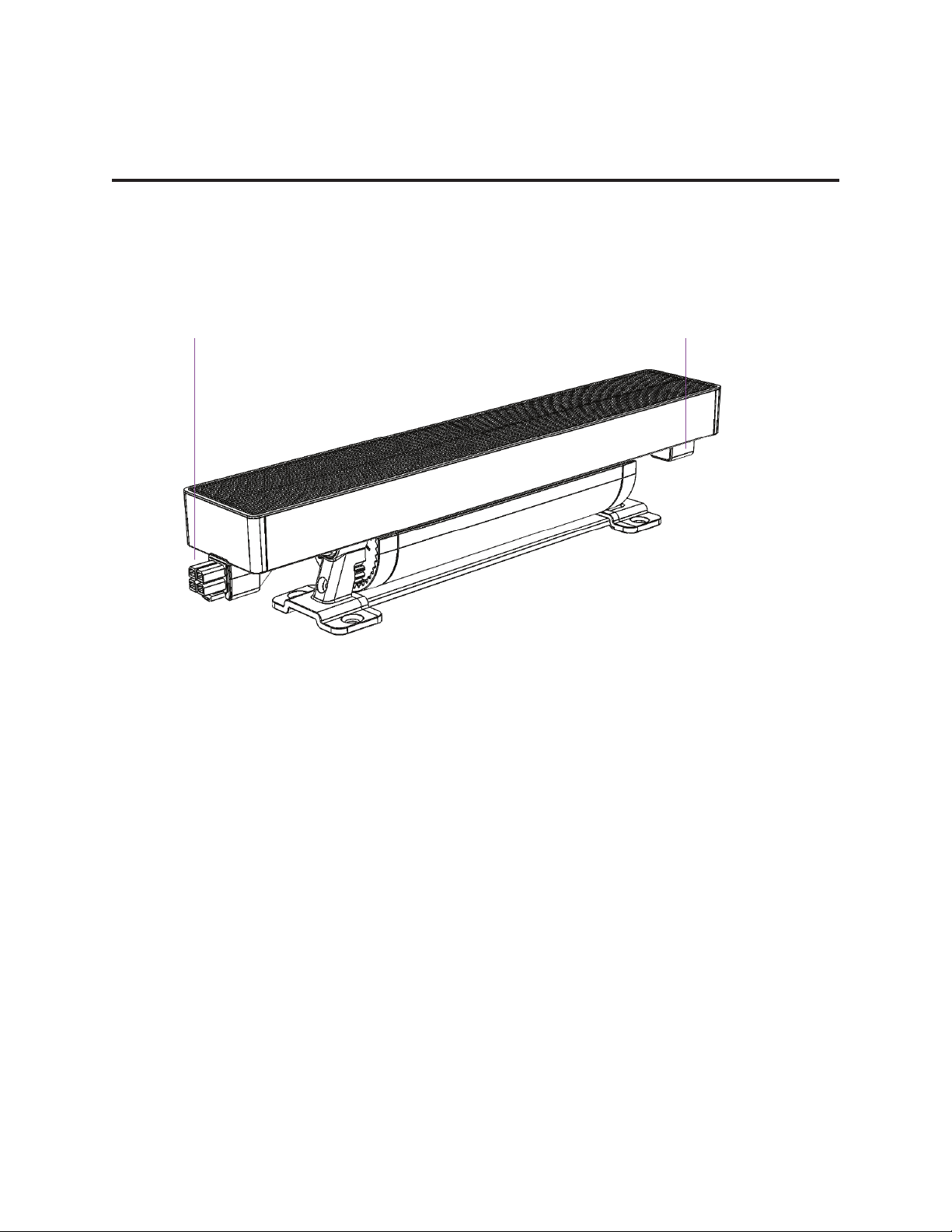
G2 linear unit
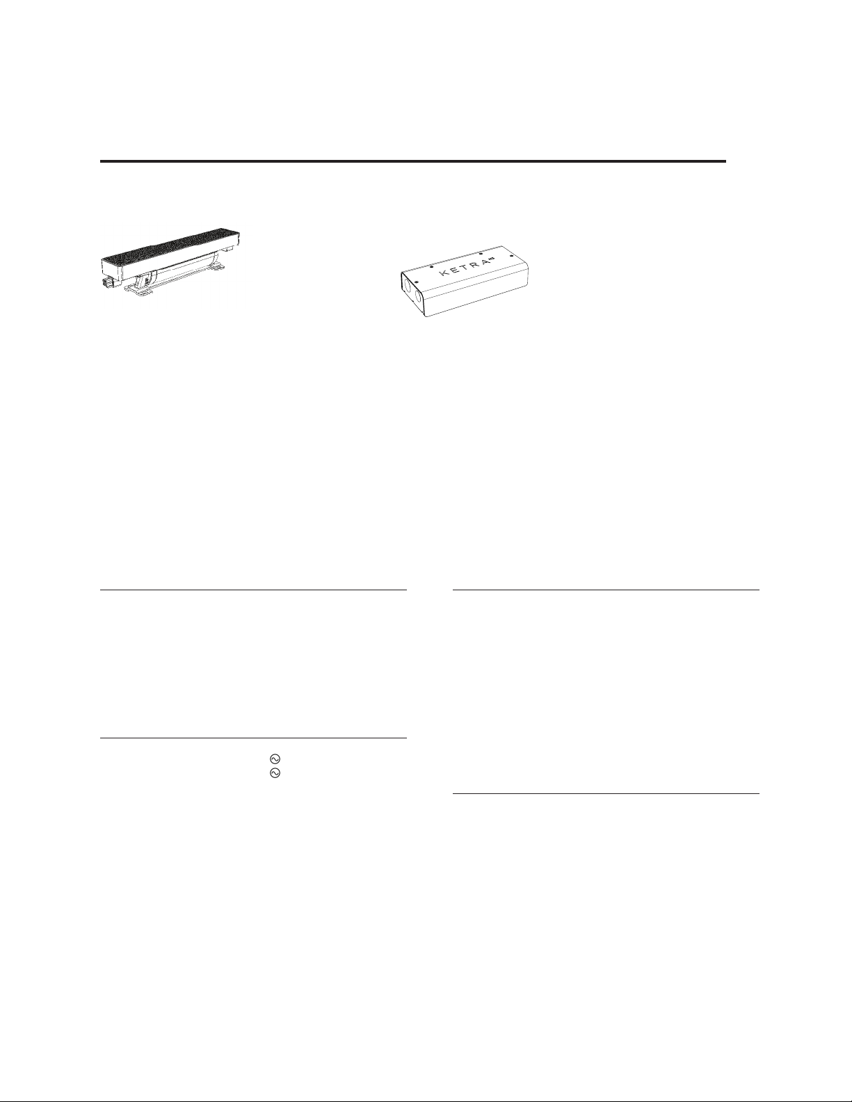
G2 System Components Include:
N3 Satellite
G2 Leader Cable
Terminator
G2 Jumper Cables as Needed
Environmental
Operating Temperature -20˚ to 40˚C
Storage Temperature -20˚ to 80˚C
Humidity 0 95%, Non-condensing
Certification UL, cUL, FCC Class B, RoHS
Location UL Damp Location, IP20
Power
Voltage 120 V ,60Hz
277 V , 60Hz
Power Consumption G2.10 15.5 W/ft (304.8 mm)
G2.07 11 W/ft (304.8 mm)
G2.04 7.7 W/ft (304.8 mm)
Current at 220V G2.10 0.07 A
G2.07 0.05 A
G2.04 0.04 A
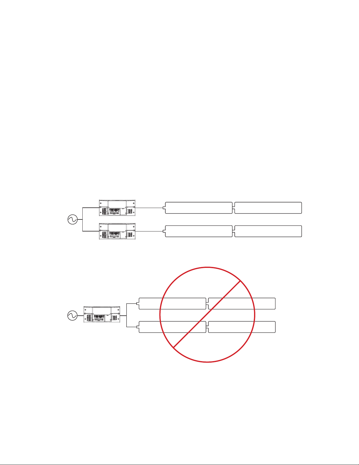
Max. Qty of Fixtures Per N3 40
Max Total Run Length,
including cable, per N3
100 ft (30.48 m)
Optical
Lumen Output G2.10 1000 lm/ft
G2.07 700 lm/ft
G2.04 400 lm/ft
CRI >90
Lumen Maintenance 50K Hours to
L70 at 25 °C Ambient
Beam Angles 10×60°, 30×45°,
60×60°, 120×120°
Dimming Range 0.1100% lm output
Electrical
Weight 1.35 lbs, 600 g
Housing Material Powder Coated Aluminum,
Polymer
Lens Material Non-yellowing heat/ UV
stabilized PMMA
PAGE 5770-0000XX-0X-0XG2 INSTALLATION GUIDE
G2 LINEAR UNIT
TERMINATOR
G2 SYSTEM
COMPONENTS INCLUDE
N3 SATELLITE UNIT
G2 LEADER CABLE
G2 JUMPER CABLES
AS NEEDED
BK: Black
AU: Aura
038: Par 38
NS: Narrow Spot
SP: Spot
FL: Flood
Series Beam Angle
2: Japan - 100V, 50/60 Hz
1: NA - 120V, 60 Hz
SL: Silver
WH: White
G: GU24
E: E26
RegionSize Housing Color Base
770-000003-01-28
© 2016 Ketra, Inc. All rights reserved.Designed in Austin, Texas +1.512.347.1100 |www.ketra.com
Specications are subject to change without notice.
G2 HIGH OUTPUT LINEAR ACCENT
Project:
Comments:
Prepared By:
Optical Performance
Lumen Output2
G2.10 1000lm/ft,
G2.07 700lm/ft,
G2.04 400lm/ft
CRI >90
Lumen Maintenance3 50K Hours to L70@25°C Ambient
Color Spatial Uniformity <2 MacAdam ellipses across eld angle
Color point maintained to <1 MacAdam ellipse over product lifetime
Beam Angles 10x60°, 30x45°, 60x60°, 120x120°
Dimming Range 0.1-100% lm output
Mechanical
Weight (12”) 1.35 lbs, 600 g
Housing Material Powder Coated Aluminum, Polymer
Lens Material Non-yellowing heat/ UV stabilized PMMA
Electrical
Power Consumption
G2.10 19W/ft TYP,
G2.07 12W/ft TYP,
G2.04 7W/ft TYP
Power Factor >0.9
Current
G2.10 0.16 A
G2.07 0.1 A
G2.04 0.06 A
Ecacy
G2.10 53lm/W TYP,
G2.07 60lm/W TYP,
G2.04 57lm/W TYP
Max. Qty of Fixtures Per N3 40
Max Total Run Length, including cable, Per
N3 100ft
Accessories
Leader 50’, White (with Terminator) G2L6001CWH
Leader 50’, Black (with Terminator) G2L6001CBK
Leader 10’, White (with Terminator) G2L1201CWH
Leader 10’, Black (with Terminator) G2L1201CBK
Lead Out 10’, White G2LO1201CWH
Lead Out 10’, Black G2LO1201CBK
Jumper 1’, White G2J0121CWH
Jumper 1’, Black G2J0121CBK
Jumper 5’, White G2J0601CWH
Jumper 5’, Black G2J0601CBK
Jumper 10’, White G2J1201CWH
Jumper 10’, Black G2J1201CBK
Jumper 25’, White G2J13001CWH
Jumper 25’, Black G2J3001CBK
Terminator (Optional Replacement) GTC
G2 Hex Louver, White (NFL, FL, WFL) G212AHEXLUVWH
G2 Hex Louver, Black (NFL, FL, WFL) G212AHEXLUVBK
G2 Alignment Track G2TRKZP48
N3 Satellite N3INDREC1BK
Environmental
Ambient Operating Temperature -20 to 50°C
Storage Temperature -20 to 80°C
Humidity 0 - 95%, Non-condensing
Certication UL, cUL, RoHS
Location UL Damp Location, IP20
Specifications1
1 All performance measurements taken with xture stabilized at 25°C ambient, 100% power input, unless otherwise stated, within CCT range of 2700 - 5000K.
2Lumen measurement complies with IES LM-79-08 testing procedures.
3Lumen maintenance values calculated in accordance to TM-21 procedures based on LM-80 compliant measurement data.
Form Factor
Dimensions:
Beam Angle: Dim A Dim B Dim C
Wide Flood
12”, 305 mm 2”, 50.8 mm
2.5”, 63.5 mm
Flood 2.5”, 63.5 mm
Narrow Flood 2.65”, 67 mm
Graze 3.1”, 78.7 mm
Rotation Innite adjustment through 180°
5|G2 INSTALLATION GUIDE
770-000003-01 r09
© 2019 Ketra, Inc. All rights reserved