Setting Up for Operation
When unpacking the unit make all hookups and connections before plugging in the AC power
adapter.
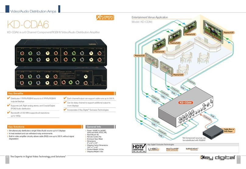
This unit will accept virtually any component video input signal (Y, Pr, Pb) with a matching left and
right stereo audio pair (L/R audio can be substituted by a single digital PCM audio connection) and
distribute it to several “Display” devices around your home or showroom without the loss of signal.
A typical hookup will consist of a “Source” device that outputs component video (or S-Video with
an optional component video adapter) such as a DVD player, Set-Top Box unit, Satellite receiver,
digital VCR, Sony Playstation
™
, XBOX
™
, GameCube
™
or any other consumer video device.
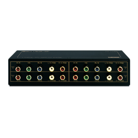
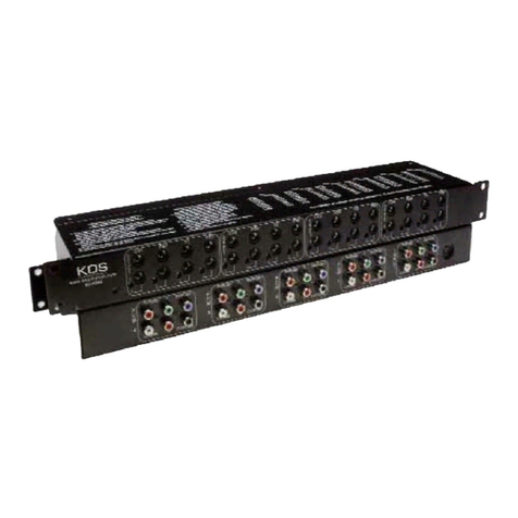
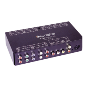
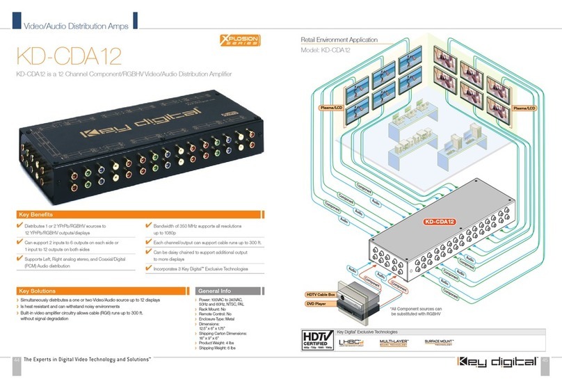
The “Source” device should be connected to the jacks marked “Input” on the KD-CDA12P. After
hooking up the “Source” device to the marked input connectors, the KD-CDA12P will distribute the
selected input signal to all of the output connectors. There are two banks (Marked Channel 1 and 2,
each corresponding to their respective inputs) of output connectors. Each of the RCA connectors
are color coded to match most “Source” and “Display” devices available in the consumer industry;
Red, Green and Blue for Component video; White, and Red for left and right audio respectively
(PCM audio can be distributed by using either the left or right audio channel).
Connecting your Unit
Typically, connecting the KD-CDA12P is as simple as matching the proper color coded connectors.
When inserting the RCA connectors use a slight twisting motion when inserting the cables, this
assures a proper connection by seating the RCA connector all the way in.
Be careful not to confuse the Red lead of a component video cable with the Right or Red audio
channel. Most often the audio wire is together with a White or Left audio lead! The Red lead from
the component video cable is often attached to the Green and Blue lead from the component
cable as well.
When running long lengths of cable please make sure to use heavy shielded high quality cables.
Now that the input(s) are connected, run each of the individual set of output connectors to their
respective “Display” devices. Make sure to use the correct wires when making the connections to
the “Display” device (use the color matching system if possible.)
Now that the installation is done it is recommended to double check all connections before
connecting the external power supply. Once every connection has been verified, plug the external
power supply connector into the power input jack of the KD-CDA12P. Once power has been
applied, a green light should show the power “ON” status on the front of the unit. Use a reliable
“Source” to test your connections (Like a DVD player).
Mounting and Maintenance instructions
The KD-CDA12P is built for years of trouble free operation. Cleaning or maintenance is usually not
necessary, but if needed use a soft non-abrasive dry cloth to wipe the dust from the unit.
Since the KD-CDA12P produces a small amount of heat, it is recommended to leave a few inches
of room around the unit to dissipate this heat.
Configuration Modes
The KD-CDA12P can be configured in 3 separate modes:
Set the slide switch to one of the following modes of operation.
Mode1: 2 inputs, each driving 6 outputs (this is the factory default mode)
Mode2: 1 input driving 12 outputs with the unused input driving the next distribution amplifier
Mode 3: 1 input driving 12 outputs
Mode 1:
Green LED on. The KD-CDA12P has two sets of inputs. This allows for independent connection
of two “Source” devices and usage of the KD-CDA12P as two separate KD-CDA6 units (these are
Key Digital
™
6-channel distribution amplifiers). Using this configuration it is possible to distribute two
discrete Audio/Video signals to two banks of 6 “Display” devices. This is the factory default mode.
Mode 2:
Green and Red LEDs on. The KD-CDA12P can also be cascaded or “Daisy Chained”. Using
this hookup method allows multiple units to be connected in series. One of the two inputs is for
receiving the Source or input signal; the other input is used for the “Loop-Through” signal, for
passing the input signal to the next amplifier in the chain of series. Either input can be used as
the “Source” input or as the “Loop-Through” input (to send the signal to the next KD-CDA12P or
KD-CDA6.) The Mode 2 setting is used for all KD-CDA12P units in the chain except for the last unit,
which must be set to Mode 3 (See below). A maximum of 4 KD-CDA12P can be connected in a
“Daisy Chain” using this hook-up method.
Mode 3:
Red LED on. The KD-CDA12P can be configured to distribute 1 input “Source” to 12 different
“Display” devices.
Note: The factory default setting of the slide switch is Mode 1 (2x6 mode)!
Now that the installation is done it is recommended to double check all connections before
connecting the external power supply. Once every connection has been verified, plug the external
power supply connector into the power input jack of the KD-CDA12P or KD-CDA6. Once power
has been applied, a green light should show the power “ON” status on the front of the unit. Use a
reliable “Source” to test your connections (Like a DVD player).
1.
2.
3.
›
