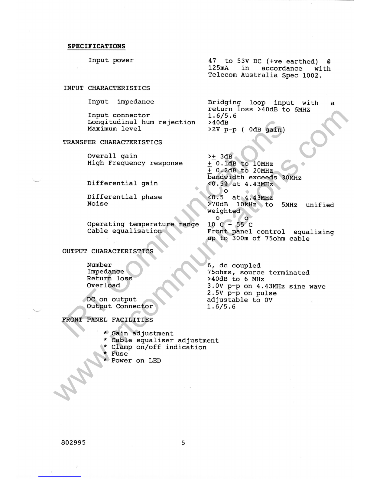
IRT VA-100NC User manual

I
IR T
ElectronicsPty.Ltd.
A.C.N.
000832575
26
Hotham
Parade,
ARTARMON.
N.S.W.
2064
Australia
National:
Phone:
(021
439
3744Fax:
(02)
439
7439
International:
+612 439
3744
+612 439
7439
VA-100NC
VIDEODISTRIBUTIONAMPLIFIER
Telecom
Serial
347
Item
55
802995
21-10-1991
DESIGNED
AND
MANUFACTURED
IN
AUSTRALIA
IRT Communications
www.irtcommunications.com

VA-100NC
VIDEO
DISTRIBUTION
AMPLIFIER
INSTRUCTION
BOOK
Serial
347
Item
55
Section
Contents
Page
1.
General
Description
3.
2.
AccessoriesAvailable
4.
3.
Technical
Specifications
5.
4.
CircuitDescription
6.
5.
Installation
7.
6.
Setting
up
Procedure
7.
7.
Maintenance
8.
8.
Table
of
Voltages
9.
9.
CircuitDiagrams
10.
PartsLists
WARNING
OPERATION
OF
ELECTRONICEQUIPMENTINVOLVES
THEUSEOF
VOLTAGES
AND
CURRENTSWHICH
MAYBE
DANGEROUS
TO
HUMANLIFE.OPERATING
PERSONNELSHOULDOBSERVE
ALL
SAFETYREGULATIONS.
DONOT
CHANGE
COMPONENTS
OR
MAKEADJUSTMENTSINSIDE
THE
EQUIPMENTWITHPOWER
ON
UNLESSPROPERPRECAUTIONS
ARE
OBSERVED.
NOTETHATUNDERCERTAIN
CONDITIONSDANGEROUSPOTENTIALS
MAY
EXIST
IN
SOMECIRCUITSEVEN
THOUGHPOWERCONTROLS
AREINTHEOFF
POSITION.
802995
IRT Communications
www.irtcommunications.com

GENERAL
DESCRIPTION
The
VA-100NC
isa
B.C.
poweredVideoDistributionAmplifier
of
modularconstructionhavingfacilities
for
cable
equalization,
longitudinal
hum
reduction
and
clamping.
The
input
is
designed
to
provide
a
bridgingloopimpedance
over
the
videobandwidthwithrespect
to75
ohm.
Six75ohm
D.C.
coupledoutputs
are
provided.
The
input
and
outputgrounds
are
separated
to
allow
for
rejection
of
longitudinallydevelopedhum.
Cableequalization
is
provided
forupto300
metres
of75ohm
videocable.
Front
panel
controls
allow
the
videogain
tobe
varied
bya
minimum
of+/-
3dB,
andthe
cableequalisation
tobe
independently
setto
compensate
forthe
appropriatelength
of
cable.Internal
pre-set
controls
allowadjustment
ofthe
amplifierhighfrequency
response,
optimization
ofthe
longitudinal
hum
rejection,
and
outputstageD.C.component.
The
VA-100NC
is
operatedfromnegative
48V
D.C.
Equipment
provided:-
1
VA-100NCVideoDistributionAmplifier
1
SlideTray
1
RB-1NRearAssembly
802995
IRT Communications
www.irtcommunications.com

ACCESSORIES
AVAILABLE
F-100D
ModuleMountingFrame
:-
Providesmounting
forupto10
VA-100NCamplifiersside
by
side
in
134mm
of
standardRackspace.
(3
Rack
Units)
TME-1AModuleExtender:Enables
a
module
to
be
operated
in
position
and
provide
access
toall
circuitboards,transistors
and
internaladjustments.
RB-1NRearAssembly:
An
additionalrear
assembly
maybe
purchased
to
permit
benchtesting
and
servicing
ofthe
amplifier
withoutdisturbing
the
rearassembliessuppliedwith
the
amplifiers.
802995
IRT Communications
www.irtcommunications.com

SPECIFICATIONS
Inputpower
INPUTCHARACTERISTICS
Inputimpedance
Inputconnector
Longitudinal
hum
rejection
Maximum
level
TRANSFER
CHARACTERISTICS
Overallgain
High
Frequency
response
Differentialgain
Differentialphase
Noise
Operatingtemperaturerange
Cable
equalisation
OUTPUT
CHARACTERISTICS
Number
Impedance
Returnloss
Overload
DC
on
output
OutputConnector
FRONT
PANELFACILITIES
47to53VDC
(+veearthed)
@
125mA
in
accordancewith
Telecom
AustraliaSpec1002.
Bridging
loopinputwith
returnloss>40dB
to
6MHZ
1.6/5.6
>40dB
>2V
p-p( OdB
gain)
>+
3dB
+
O.ldB
to
10MHz
+
0.2dB
to
20MHz
bandwidthexceeds30MHz
<0.5%
at
4.43MHz
o
<0.5
at
4.43MHz
>70dB
10kHz
to
5MHzunified
weighted
oo
10
C - 55C
Frontpanelcontrolequalising
up
to
300m
of
75ohmcable
6,
dc
coupled
75ohms,
sourceterminated
>40dB
to6 MHz
3.0V
p-pon
4.43MHz
sinewave
2.5V
p-pon
pulse
adjustable
to0V
1.6/5.6
*
Gainadjustment
*
Cableequaliseradjustment
*
Clamp
on/off
indication
*
Fuse
*
Power
onLED
802995
IRT Communications
www.irtcommunications.com

CIRCUITDESCRIPTIONRefer
to
Drawing
no.
802995.
The
blockdiagramshowsthat
the
VA-100NCcomprises
:-
(a)An
input
stage:-
which
hasa
highinputimpedance
to
bridge
the
videosource,
an
equaliser
for
correction
of
input
coaxial
cablelosses,
anda 75ohm
sourceterminatedoutput.
(b)A
"plug-in1
area:
- for
accessories
not
Link
2
bypassesthis
feature.
yet
defined.
(c)An
output
stage:-
with
6 75ohm
sourceterminated
outputs.Thisstage
may
have
its
blacklevelclamped
to0Vby
placing
LK1
inthe
'On'
position.
(d)
Clamp
logic:-
a
syncseparator
and
backporchsample
pulse
generator
isfed
from
the
output
ofthe
Inputstage.Video
from
the
output
ofthe
Outputstage
is
firstly
low
passfiltered
(to
removechroma
and
noise)
and
thenapplied
toa
sampleswitch.
This
switch,
undercontrol
ofthe
samplepulse
stores
ina
sample
and
holdcapacitor
the
backporcherrorsignal.
If
LK1
isinthe
'On'
positionthiserror
is
applied
tothe
invertinginput
ofthe
Outputstage
to
correct
the
offset.
(e)
Power
Supply:-
the
-48V
DC
inputvoltage
isfedviaan
on
boardfuse
toa
DC-DCconverter.
The
output
ofthe
converter
is
+ and-
15V.Thesesupplies
are
furtherregulated
to+ and-
12V
by3
terminalregulators.
TheLEDonthe
frontpanel
is
wired
in
series
with
a
zener
diodebetween
+12and-12
Volts.
The
zener
is
to
ensurethat
theLED
extinguishes
ifanyoneofthe
regulatorsfails.
Video
Clamp
On
LK1
enablesback
porchclamp
Off
disables
back
porch
clamp
Accessories
Inserted
LK2
by-passes
accessories
Removed
accessories
can
be
inserted
802995
6
IRT Communications
www.irtcommunications.com

INSTALLATION
The
VA-100NC
is
suppliedwith
a
slidetray,rearassembly
and
associated
hardware,
for
mounting
inan
F-100D
frame.
SlideTray
The
slidetray
isa
shallowtraywhichsupports
the
amplifier
in
the
frame.
Itis
mounted
onthe
front
and
rearcrossmembers
of
the
frame
andis
fixed
in
placewithsteelclips(speed
nut
type)provided.
RearAssembly
The
rearassembly
is
mounted
onthe
rear
ofthe
framewith
the
screwsprovided.Careshould
be
taken
notto
overtighten
thesescrews,
as
excessiveforcewilldamage
the
thread
inthe
mountingframe.
SignalConnections
Signalconnections
are
made
via
coaxialconnectorsmounted
on
the
rearassembly.
The
inputloop,
ifnot
usedshould
be
terminated
in75ohmas
should
any
unusedoutputs
ofthe
amplifier.
SETTING
UP
PROCEDURE
The
amplifiershould
besetupinthe
position
in
which
itis
intended
tobe
operated.Adjustments
can
then
be
madeusing
the
intendedlengths
of
cable
and
with
all
outputsterminated
as
they
would
bein
service.
The
cableequalizingshould
besettoits
minimum
andthe
gain
controladjusted
to
give
the
required
low
frequencygain.
Using
a
suitabletestsignal,such
as
pulse
and
bar,multiburst
or
sweep,
the
cableequalization
canbe
advanced
to
compensate
for
inputcablelosses.
It
should
be
notedthat
the
equalizers
are
factory
setto
match
Beldentype8281
75ohm
cable.
Whilst
for
short
runs
thisequalizerwill
be
satisfactory
for
most
75ohm
soliddielectriccables,
for
longerruns
of
some
cables
the
equalizer
may
have
tobe
reset
(a
factoryadjustment)
or
replacedwith
a
speciallydesignedmodule.
If
backporchclamping
is
required
LK1
should
beputinthe
'Clamp
On1
position
andthe
Clamp
OnLEDonthe
frontpanel
802995
7
IRT Communications
www.irtcommunications.com

shouldilluminate.
If
clamping
isnot
required
LK1
should
bein
the
'Clamp
Off
position.
802995
8
IRT Communications
www.irtcommunications.com

MAINTENANCE
Oncehavingbeenadjusted
the
VideoDistributionAmplifier
will
needlittleattention.
Itis
wisehowever
to
occasionally
check
the
adjustments
as
describedearlier.Thiswillalso
be
necessaryafter
a
component
has
beenreplaced.
Mostfaults
canbe
readilytraced
by
checking
the
B.C.
voltages
at
variouspoints
inthe
circuit.
The
table
of
voltages
given
in
this
book
canbe
used
asa
guide
but
deviations
sometimes
inthe
vicinity
of
+/-1volt
canbe
expected
in
some
units.
The
voltagesshould
be
checkedstartingfrom
the
input
as
the
B.C.
conditions
ofthe
wholeamplifier
aresetinthe
first
stage,
thus
a
faultearly
inthe
circuitwillcauseerrors
atthe
output.
InternalAdjustments
The
followingadjustableresistors
and
capacitors
are
factory
setand
should
notbe
adjustedunless
a
component
has
beenchanged.They
arenot
'operational1
controls.Before
adjusting
anyof
thesecontrolsallowtime
forthe
VA-600
to
reach
temperaturestability.
RV3
Hum:-
Adjusted
to
bestcancel
humonthe
inputcable.
The
clamp
must
notbein
operationduringthisadjustment.
RV1
BC
Offset:-
With
no
inputsignalapplied
RV1is
used
tosetthe
junction
of
R12R14to
zerovolts.
C2
Freq
Resp:-
Used
tosetthe
frequencyresponse
ofthe
inputstage
to
maximal
flatnesswhenobserved
atthe
junction
ofR12
R14.
RV4
BC
Offset:-
With
no
inputsignal
and
with
LK1
installed
and
after
adjustment
of
RV1,
RV4canbe
adjusted
so
that
the
junction
of
R29R30is
zerovolts.
C5
FreqResp:-
Used
tosetthe
frequencyresponse
ofthe
outputstage.
Maladjustment
of
thiscapacitor
can
causeinstability
inthe
amplifier
underextremeconditions.
802995
IRT Communications
www.irtcommunications.com

TABLE
OF
VOLTAGES
Q
Emitter
Base
Collector
1
-0.72
~0
11.2
2
-0.66
~012
3
12
11.30.82
4
0.240.82
12
5
-0.25-0.85
-12
6
-0.67
~0
11.3
7
-0.66
~012
812
11.31.65
9
0.3
0.98
12
10
-0.2-0.85
-12
11
1.0312.6
12
120
0.670.21
130
0.670.26
14
0.6
0.46-11.97
15
0.981.65
12
16
-0.68
~012
U12345678
3
~00 ~0-12
-11.9-0.5
12
-0.14
4
11.94
0 0 -12
-11.65
0 12
11.94
5
150 12
6
0 -15-12
All
voltagesmeasuredwith
a
highinputimpedancemultimeter
under
conditions
of
unitygain.
All
voltages
are
measuredwith
respect
to
earth.Supplyvoltage
is
-50.0V
B.C.
Testsignal
is
IV
P-P
compositeStairStep
andthe
Clamp
is
off.
802995
10
IRT Communications
www.irtcommunications.com

z
m
ni
?
8
Ul
0!
fl!
pi
O
<O
?
|
1
H
B
3HSSI
1VNIOIWO
IRT Communications
www.irtcommunications.com

IV
P -P
TERMINATED
0-SV
P-P
OPTIONAL
PLUG-IN
BOARD
f-J
! I
iI I
SAMPLE
SWITCH
IV
P-P
TERMINATED
6
OUTPUTS
-
*6V
INPUT
DC
-DC
CONVERTER
+
I5V
~*
-ISV
+
-
1
1
TliV
I
^
^
POWER
IRT
DftAWN
3&AA
Q*TE
•IXI
SCALC
VA-lOO
NC
BLOCK
DIACKAM
8OZ9S5
SHEET
•2.
or
3.
IRT Communications
www.irtcommunications.com

/T
PART
OF
VA—
1OONC
CIRCUIT
/
\G CHANGEDCOMPONENTS
IFOR
SPECIFICATION
1227
H
RV2
,
J
2SOR
FT
EQ*
R62
1
CUD
f
'
51R
C16
I
82PT
?
SPECIFICATION
1
5S7
R63
p
cm!
T
—
1
243R
aci7
ciaj_
_
"*
6Op1
SOpT"
^
R64
1
J
f
1K1
2C19
C2O_|_
_
""
6Op
82p~T
'
R65
l==l
1
12K
2
C21
C22|
60p
22p
|
i
1
9
g
2
©
COPYRIGHT
DO
NOT
COPY
NOR
DISCLOSE
TOANY
THIRD
PARTY
WITHOUT
WRITTEN
CONSENT
DRAWN
K.N.
CHECKED
ENO.
APP.
CONTRACT
No.
DLEU
SIZE:
SCALE
TITLE:
VA—
IOONC
CABLE
COMPENSATION
TO
SPECIFICATION
1227
SPECIFICATION
1 557
DRAWING
No.
8O29B5
SHEET
3OF3
IRT
Electronics
Pty.Ltd.
ARTARMON
NSW
AUSTRALIA
2O84-
IRT Communications
www.irtcommunications.com

ORIGINAL
ISSUE
DATE
IT.
-3-
84
II
ll
Is
a
H
CD
O
(P
©
ooooooo
ooooo
*•
in
060
o—
IRT Communications
www.irtcommunications.com

I.R-T -
ELECTRONICS
»TY
.
LTD
.
Replacement
PartsList
802995
VIDEODISTRIBUTIONAMPLIFIERASSEMBLY
VA-100NC
Page
1 of4
!
Part
No.
PC802994
SFR16T-1R8
SFR16T-4R7
SFR16T-22R
SFR16T-27R
SFR16T-33R
SFR16T-68R
SFR16T-75R
SFR16T-100R
SFR16T-120R
SFR16T-150R
SFR16T-220R
SFR16T-270R
SFR16T-360R
SFR16T-470R
SFR16T-820R
SFR16T-1K
SFR16T-1K2
SFR16T-1K5
SFR16T-3K9
SFR16T-4K7
SFR16T-5K6
SFR16T-10K
SFR16T-12K
SFR16T-22K
SFR16T-33K
SFR16T-47K
SFR16T-82K
Description.
PCS
VA-100NC
RESISTOR
METALFILM
.25W
5%
RESISTOR
METALFILM
.25W
5%
RESISTOR
METALFILM
.25W
5%
RESISTOR
METALFILM
.25W
5%
RESISTOR
METALFILM
.25W
5%
RESISTOR
METALFILM
.25W
5%
RESISTOR
METALFILM
.25W
5%
RESISTOR
METALFILM
.25W
5%
RESISTOR
METALFILM
.25W
5%
RESISTOR
METALFILM
.25W
5%
RESISTOR
METALFILM
.25W
5%
RESISTOR
METALFILM
.25W
5%
RESISTOR
METALFILM
.25W
5%
RESISTOR
METALFILM
.25W
5%
RESISTOR
METALFILM
.25W
5%
RESISTOR
METALFILM
.25W
5%
RESISTOR
METALFILM
.25W
5%
RESISTOR
METALFILM
.
25W
5%
RESISTOR
METALFILM
.25W
5%
RESISTOR
METALFILM
.25W
5%
RESISTOR
METALFILM
.25W
5%
RESISTOR
METALFILM
.25W
5%
RESISTOR
METALFILM
.25W
5%
RESISTOR
METALFILM
.25W
5%
RESISTOR
METALFILM
.25W
5%
RESISTOR
METALFILM
.
25'W
5%
RESISTOR
METALFILM
.25W
5%
Qty
1
1
2
7
1
1
1
2
2
1
1
2
3
1
4
3
5
4
3
2
4
3
1
1
i
1
1
1
Get
Ref.
R8
R29,30
R5,
6,
12,13,
19,
20,
61
RIO
R27
R60
R14,17
R62,67
R74
R18
R3,4
R22,46,71
R63
R15,16,25,57
R7,21,72
R28/41-43,69
R9,
11,64,
70
R23,24,75
R2,68
R48,51,54,65
Rl,49,52
R26
R56
R50
R53
R55
R58
Sup!
•
120:
58:
58:
58:
58:
58:
58:
58:
58:
58:
58:
58:
58:
58:
58:
58:
58:
58:
58:
58:
58:
58:
58:
58:
58:
58:
58:
58:
802995
17/10/91
IRT Communications
www.irtcommunications.com

I.R.T .
ELECTRONICS
I»TY
. LTD-
Replacement
Parts
List
802995
VIDEODISTRIBUTIONAMPLIFIER
VA-100NC
Page
2 of4
1
Part
No.
SFR16T-100K
SFR16T-270K
RMF255-3M3
RMF251-75R
ASW-2-6R8
WA2G024S251U
3329H-101
3329H-102
CC4P7
CC8P2
CC47P
CC100P
CC120P
CC150P
CC390P
CC10N
CC22N
CC47N
CC100N
CP10N/63V
TT1/35
TT22/16
RT47/63
RB220/16
TZ032070E
TZ03P600E
Description.
RESISTORMETALFILM
.25W
5%
RESISTORMETALFILM
.25W
5%
RESISTORMETALFILM
.25W
5%
RESISTORMETALFILM
.25W
1%
RESISTORWIREWOUND
2W
RESISTORVARIABLE
2
5
OR
RESISTORVARIABLE100R
RESISTORVARIABLE
IK
CAPACITORCERAMIC
4
.
7pF
CAPACITORCERAMIC
8
.
2pF
CAPACITORCERAMIC
47pF
CAPACITORCERAMIC
lOOpF
CAPACITORCERAMIC120pF
CAPACITORCERAMIC150pF
CAPACITORCERAMIC390pF
CAPACITORCERAMIC10nF
CAPACITORCERAMIC22nF
CAPACITORCERAMIC47nF
CAPACITORCERAMIC
lOOnF
(Z5U)
CAPACITOR
POLY
10NF
63V
CAPACITOR
TAG
TANT
luF/35V
CAPACITOR
TAG
TANT
22uF/16V
CAPACITORELECTRO47uF/63V
CAPACITORELECTRO220uF/16V
CAPACITORVARIABLE2-7pF
(BLUE)
CAPACITORVARIABLE
10-60pF
(BROWN)
Qty
1
1
1
6
1
2
1
2
1
1
1
3
4
2
1
5
1
1
7
2
2
7
1
1
2
3
Get
Ref
.
R44
R47
R45
R31-36
R73
RV2,5
RV3
RV1,4
C13
C4
C6
C9,
11,22
C7,14,15,20
C16,18
C8
CIO,
31,32,
33,
34
C24
C12
ClOO-103,106,107,110
C35,36
C26,29
C27,
30,
104,
108,
109,
111,
112
C37
Cl
C2,5
C17,19,21
Sup|
•
•
58:
58:
58:
92:
•
•
•
*
•
•
•
•
•
•
•
•
58:
58:
58:
58:
58:
58:
51:
58:
:
•
•
•
•
•
•
81:
81:
51:
51:
802995
17/10/91
IRT Communications
www.irtcommunications.com

.T -
ELECTRONICS
Replacement
PartsList
802995
VIDEODISTRIBUTIONAMPLIFIER
VA-100NC
Page
3 of4
!
Part
No.
1N4148
1N4004
BZT03C68
BZX79C15
LEDGN5MM
2N3904
2N3906
2N2222
2N2905
2N2907
2N4959
2N3866
7812
7912
CA3080
LM310N
UM915
IM-2
4.7
IM-2
10
IM-2
100
IM-2
150
26-4100-24P
1100-1-124-03
ZTMJB505
2270B
Description.
DIODE
75V
100mA
DIODEPOWER
1A
DIODEZENER
68V
DIODEZENER
15V
LED
GREEN
HF
TRANS
TO-92
NPN
HF
TRANSTO-92
PNP
HF
TRANS
TO-
18
NPN
HF
TRANS
TO-39
PNP
HF
TRANS
TO-
18
PNP
RF
TRANS
TO-
18
PNP
RF
TRANSTO-39
NPN
1C
REGULATOR
12V1A
1C
REGULATOR
-12V
1A
OPERATIONAL
TRANS
COND
AMP
OP
AMP
BUFFER
DC/DC
CONVERTER
48/2x15
INDUCTOR
4.7uH
INDUCTOR
lOuH
INDUCTOR
lOOuH
INDUCTOR
150uH
CONNECTOR
24PIN
PC
HEADER
PC
HEADER
(GOLD)
SHORTINGLINKS
30u
GOLD
HEAT
SINK
Qty
5
1
1
1
2
8
2
1
1
1
2
1
1
1
1
1
1
5
3
1
1
1
.66
.12
1
2
Get
Ref.
Dll-15
Dl
D2
D10
LD1,2
Ql,2,6,7,12,13,15,16
Qll,14
Q4
Q10
Q5
Q3,8
Q9
U5
U6
U3
U4
XI
L3-7
L9,10,ll
LI
L2
PL1
PL2,3
LK1
Sup!
•
•
*
•
81:
81:
51:
51:
51:
97:
97:
97:
97:
97:
97:
97:
97:
97:
54:
81:
81:
54:
54:
54:
54:
J
99:
99:
99:
81:
802995
17/10/91
IRT Communications
www.irtcommunications.com

-
R.T
ELECTRONICS
.
H.TD
.
Replacement
PartsList
802995
VIDEODISTRIBUTIONAMPLIFIER
VA-100NCPage
4 of4
!
Part
No.
E803183
W3108T
L1426
20x5
.250
SL48
021-1220
040-1620
5022
801576
800028
800029
801775
SBV1700/14/16
SNU/0520/17/4
Description.
ESCUTCHEON
1C
SOCKET
8 PIN
OPENFUSEHOLDER
(PCB)
FUSE250mA
LED
HOLDER
KNOBBLACKWITHLINE
CAP
BLACKWITHLINE
CO-AXIALCABLE
HANDLE
S/W
COVER
S/W
MODULE
FRAME
S/W
MODULE
SIDECOVER
BRASSSTUD
"U"
NUTS
Qty
1
2
1
1
2
2
2
.3
1
1
1
1
1
1
Get
Ref.
SupJ
62
99
1
62
99
1
1
1
1
802995
17/10/91
IRT Communications
www.irtcommunications.com

T*
m
JL
•
Replacement
PartsList
801180
REARASSEMBLY
RB-1N
ISSUE
2
Page
1 of1
!
Part
No.
26-4200-24S
AC40334-A76-A14
25.106.0253
PC801957
PC801171
800319
800320
CAP
SCREW
4BA
Description.
CONNECTOR
24PINS
CONNECTORCOAXIAL
1.5/6
TERMINALBLOCK
PCB
I/P
LOOP
COMP
REAR
PLATE
RB-lN
CHASSISREARASSY
S/W
SIDEPLATEREAR
ASSY
SCREW
ALLENHEAD
4BA
BLK
Qty
1
8
1
1
i
1
1
2
Get
Ref
.
Jl
TB1
LI
Sup|
*
*
54:
86:
61:
68:
26:
26:
26:
4
:
80118017/11/87
IRT Communications
www.irtcommunications.com
Table of contents
Other IRT Amplifier manuals