Keyscan CIM-LINK User manual

CIM-LINK Setup Guide
CIM-LINK modules, sold in sets of two, are used to establish ACU to ACU communication
between two or more communication loops over an Ethernet (TCP/IP) network for global
functions, such as global anti-pass back, global time zones, or global inputs and outputs.
This guide outlines how to connect the CIM-LINK modules and program the NETCOM2P
with the Keyscan NETCOM Program Tool utility. CIM-LINK modules only communicate over
a network (TCP/IP) using a NETCOM2P.
Before You Start
Verify that you have all the parts as outlined below.
Keyscan recommends reviewing this document and pre-planning where and how the
CIM-LINK modules are connected to create global communication within the access
control communication structure.
The NETCOM2Ps included with the CIM-LINK modules must be programmed with
static IP addresses, subnet masks, and, if applicable, gateways and Ethernet
connection types which you may have to obtain from the IT administrator
Ensure that the Keyscan NETCOM Program Tool utility, which is required for
programming the NETCOM2P and is located on the Keyscan Drivers and Utilities CD, is
installed on a PC or laptop that can be serially connected to the CIM-LINK/NETCOM2P
as outlined in the Program NETCOM2P section
Space is provided on a worksheet at the back of this setup guide for recording all
CIM-LINK jumper settings at all applicable access control units
Contents
Parts List
Pre-installation
2
CIM-LINK Modules
2
Configuration
3
Ribbon Cables
2
Jumper Settings & Power
7
Serial Programming Cable
1
Program NETCOM2Ps
11
Keyscan Drivers & Utilities CD
1
Operational Connections
19
Diagnostics
23
Specifications
28
Figure 1 –CIM-LINK Modules

Keyscan Inc. A Member of the Kaba Group
2
Pre-Installation
Keyscan suggests that you review the following material to ensure that you have the
required firmware and software versions that support the CIM-LINK modules.
CIM-LINK Requirements
The CIM-LINK module requires the following control board firmware and software versions:
Hardware - Aurora
EPROM version 9.20 or higher –door control units
EPROM version 9.20 or higher –elevator control units
Multiple ACU communication loop requires CIM-based communication configured for
ACU to ACU communication on CAN Bus 2
Software
Aurora version 1.0.1.0 or higher
NETCOM Program Tool Utility –version 6.0.13 or later
Note
For global outputs, Keyscan recommends using the global OCB-8 option. This requires the
purchase of an optional OCB-8 which connects to the control board’s Control 5 header.
Global outputs are not supported on CA200 or CA250 door control units and EC1000,
EC2000, EC1500, or EC2500 elevator control units.
Multiple Building Communication on a WAN
Keyscan requires a point-to-point private network where NETCOMs are used on a LAN/WAN
(TCP/IP) that integrates building to building communication.
Supplementary Documentation
You may also require the following Keyscan documentation which can be located on the
Keyscan Documents CD:
CIM Setup Guide
Keyscan Technical Guide
Global Inputs & Outputs/Time Zones

CIM-LINK Setup Guide
3
CIM-LINK Configuration
When using CIM-LINK modules, one communication loop must be configured as the master
communication loop and all others as subordinate communication loops. When
interconnecting two or more communication loops, install each pair of CIM-LINK modules
as follows:
Install a CIM-LINK module on the master communication loop
Install a CIM-LINK module on the subordinate communication loop
Figure 2 –CIM –CIM-LINK Modules Overview
1st Communication Loop - Master
3rd Communication Loop -
Subordinate
CIM-LINK
–Set A CIM-LINK
–Set B
2nd Communication Loop -
Subordinate
CIM-LINK
–Set A
CAN Bus 2
Virtual
network
connection
Virtual
network
connection
Subordinate loops with multiple ACUs require CAN Bus 2
CIM-LINK
–Set B
When integrating multiple communication loops, remember, one set of CIM-LINK modules
is required per the number of subordinate communication loops integrated with the master
loop. The example above shows two subordinate loops, which requires two sets of CIM-
LINK modules.
CIM-LINK modules are extremely flexible in structuring global functions across multiple
communication loops as indicated below:
A group of CIM/access control units on a CAN Bus to another group of CIM/access
control units on a CAN Bus –see Figure 3
A group of CIM/access control units (master) on a CAN Bus to a single access control
unit (subordinate) –see Figure 3
A single access control unit (master) to a group of CIM/access control units
(subordinate) on a CAN Bus –see Figure 4
A single access control unit to a single access control unit –see Figure 5
The following three block diagrams depict multiple communication loop models based on
how the CIM-LINK may be configured for global communication. Refer to the illustrations
that best approximate your particular ACU communication infrastructure. Each block
diagram lists corresponding connection diagrams to assist with your installation of the CIM-
LINK modules.

Keyscan Inc. A Member of the Kaba Group
4
Figure 3 - CIM-LINK Modules Connecting Multiple Communication Loops
CIMCIMCIM 0
ACU
Global
Master
J3 - ON
Communication Loop - Master
CIM-LINK –A
J3 OFF
J4 OFF
CIM-LINK - B
J3 OFF –Global Slave
J4 ON –Single ACU Mode
Communication Loop - Subordinate
Ethernet
CAN Bus 2
CAN Bus 2
1 CIM as Global Master on least busy
ACU.
All other CIMs are slaves.
ACU ACU
CIMCIMCIMCIM 0
ACU ACU ACU ACU
Virtual
Connections
Master Loop
- install 1 CIM-LINK for each subordinate
communication loop.
CIM-LINK A
- communicates with CIM-LINK –A Building 2
CIM-LINK B
- communicates with CIM-LINK –B Building 3
Install 1 CIM-LINK on each subordinate communication loop.
All CIMs set as slaves.
Building 1
Building 2
Input B
Input A Output
(Alarm/CCTV etc.)
Input C
Input A, Input B, Input C, and Input D programmed to fire the output in Building 1.
OCB-8 or IOCB1616
ACU
Input D
CIM-LINK –B
J3 OFF
J4 OFF
Building 3
Communication Loop - Subordinate
CAN Bus 1
CAN Bus 1
KI-00473E-09-12
Single ACU panel communication loop
requires only a CIM-LINK module.
CIM 0 –serial or network connection to PC with Communication Manager
CIM-LINK to CIM-LINK –NETCOMP only
serial or network
connection to PC
with
Communication
Manager
CIM-LINK - A
J3 ON –Group Master
J4 OFF –Group ACU Mode
See Figure 11 for connections.
See Figure 12 for connections.
See Figure 13 or Figure 14 for connections.

CIM-LINK Setup Guide
5
Figure 4 - Single ACU Communication Loop as Global Master to Multiple ACU
Communication Loop
A single access control unit communication loop designated as a global master is restricted
to one subordinate communication loop.
CIM-LINK
J3 ON –Global Master
J4 ON –Single ACU Mode
ACU
Input A
Building 1
Communication Loop - Master
Single ACU panel communication
loop requires only a CIM-LINK
module.
serial or network
connection to PC
with
Communication
Manager
Ethernet
Input A, Input B and Input C programmed to fire the output in Building 2.
Maximum of 2 ACU communication loops may be integrated for global communication
when single ACU communication loop is designated as the master communication loop.
Communication Loop - Subordinate
CAN Bus 2
CIMCIMCIMCIM 0
ACU ACU ACU ACU
All CIMs set as slaves. Building 2
Input B Input C
CAN Bus 1
CIM-LINK
J3 ON –Group Master
J4 OFF –Group ACU Mode
Virtual Connection
Output
(Alarm/
CCTV etc.)
OCB-8 or
IOCB1616
CIM-LINK
- communicates with CIM-LINK –Building 2
KI-00487E-10-12
CIM-LINK
- communicates with CIM-LINK –Building 1
See Figure 13 or
Figure 14 for
connections.
See Figure 12 for
connections.

Keyscan Inc. A Member of the Kaba Group
6
Figure 5 - Single ACU Communication Loop as Global Master to Single Subordinate
ACU Communication Loop
A single access control unit communication loop designated as a global master is restricted
to one subordinate communication loop.
CIM-LINK
J3 ON –Global Master
J4 ON –Single ACU Mode
ACU
Input A
Building 1
Communication Loop - Master
Single ACU panel communication
loop requires only a CIM-LINK
module.
serial or network
connection to PC
with
Communication
Manager
CIM-LINK
J3 OFF –Global Slave
J4 ON –Single ACU Mode
ACU
Input B
Building 2
Communication Loop - Subordinate
Single ACU panel communication
loop requires only a CIM-LINK
module.
serial or network
connection to PC
with
Communication
Manager
Ethernet
Virtual
Connection
OCB-8
Output
(Alarm/
CCTV
etc.)
Input A and Input B programmed to fire the output in Building 2.
Maximum of 2 ACU communication loops may be integrated for global communication when single ACU
communication loop is designated as the master communication loop.
KI-00486E-10-12
CIM-LINK
- communicates with CIM-LINK –Building 2
CIM-LINK
- communicates with CIM-LINK –Building 1
See Figure 13 or
Figure 14 for
connections.
See Figure 13 or
Figure 14 for
connections.

CIM-LINK Setup Guide
7
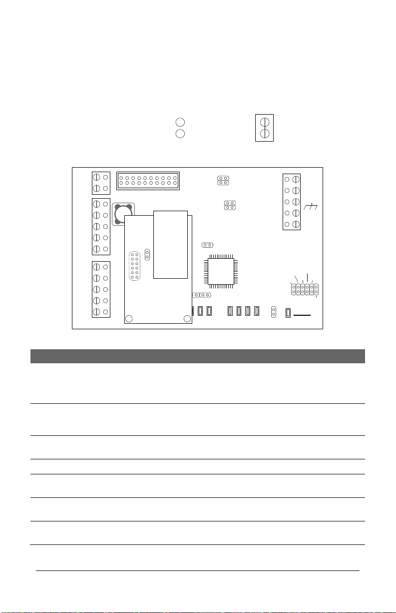
CIM-LINK Jumper Settings & Power
The CIM-LINK module interlinks multiple communication loops for global communication
using either CAN Bus 2 on multiple ACU communication loops or a direct network
connection on a single ACU communication loop. When connecting CIM-LINK modules,
ensure the units are configured with the correct jumper settings as outlined.
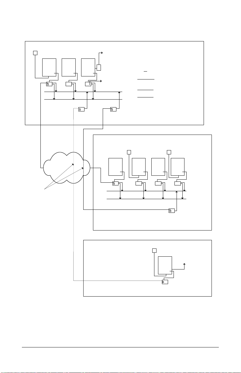
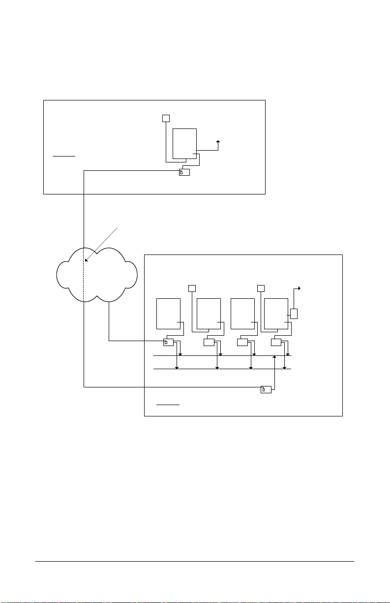
Master & Subordinate Communication Loops
When integrating CIM-LINK modules, establish one communication loop as a global master
communication loop and set all other communication loops as subordinate communication
loops. Refer to Figure 3 or Figure 4.
Master Communication Loop
Set one CIM or one CIM-LINK as the global master –jumper J3 ON
Important
A CIM-LINK can only be designated as a global master on a single ACU communication loop
and would be restricted to one subordinate communication loop.
Subordinate Communication Loop
Configure all other communication loops as subordinate in one of the following modes:
On a communication loop with multiple ACUs, set the CIM-LINK module as a group
master –jumper J3 ON
On a communication loop with a single ACU, set the CIM-LINK module as a global
slave –jumper J3 OFF
When the CIM-LINK is set as a group master with jumper J3 ON, it enables checking CIM
unit heartbeats on the communication loop.
Ensure that only one CIM or CIM-LINK is set as a global master for the entire network of
communication loops/ACUs.
Single ACU Mode / Group ACU Mode
The CIM-LINK module must be set for single ACU mode or group ACU mode.
When connected on a single ACU communication loop, set to single ACU mode –J4
ON
When connected on a multiple ACU communication loop, set to group ACU mode –J4
OFF
Termination Jumpers J5—J8
The CIM-LINK has termination jumpers J5 to J8 when the module is located at the
beginning or the end of the CAN Bus. Observe the following termination jumper settings.
CAN Bus 1 –J5 & J6 –do not apply to the CIM-LINK module, leave OFF (terminate
first and last CIM modules on CAN Bus 1)
CAN Bus 2 –J7 & J8 –if the CIM-LINK module is the first or last unit, terminate with
jumpers ON; otherwise leave jumpers OFF
Power
The method of powering the CIM-LINK module with the NETCOM2P depends on the type of
communication loop they are connected on.
Single ACU communication loop - the CIM-LINK/NETCOM2P are powered via the
ribbon cable connection from HDR1 to H2 on the control board
Multiple ACU communication loop - the CIM-LINK is powered via a connection from
the 12V terminal to a 12VDC power supply

Keyscan Inc. A Member of the Kaba Group
8
CIM-LINK Jumper Locations
The CIM-LINK modules are jumpered as indicated in the table below depending on its
function.
Figure 6 –CIM-LINK Module Jumpers
TD1
RD1
TD2
RD2
GND
RTS
CTS
GND
RTS
CTS B3 B2 B1 B0 Diag
J2
RESET
-
CAN2
+
EGND
-
CAN1
+
GND
V +
(+12V)
SCKT1
PC106x
J1
J7
J8
J6
J5
CAN2
CAN1
1 2 1 2 1 2 1 2
Rx - COM COM
CAN CAN - Tx
J3J4 J9
J12
Power
Good
COM1
COM2
HDR1
J10
J11
Fault
(Flashing)
RJ45
Terminal
Jack
J1
NETCOMP
CIM-LINK
KI-00485E-10-12
Jumper Off
Off = 0 Jumper On
On = 1
Jumper Legend
CIM-LINK Module Jumper Locations
CIM-LINK Modes
Jumper #
Setting
Notes
Reset
J1
1
Short momentarily when the
CIM-LINK has been re-
configured, otherwise leave the
jumper off.
Diagnostics
J2
1
Runs the CIM-LINK in
Diagnostic Mode. See CIM-LINK
Diagnostics section.
Global Master or Group
Master
J3
1
Global Slave
J3
0
Single ACU
J4
1
When connected on a single
ACU communication loop
Group ACU
J4
0
When connected on a multiple
ACU communication loop
CAN 1 Termination
Jumpers
J5 J6
n/a

CIM-LINK Setup Guide
9
CIM-LINK Modes
Jumper #
Setting
Notes
CAN 2 Termination
Jumpers –Group ACU
Mode
J7 J8
1 1
If the CIM-LINK is first or last
module on CAN Bus 2, set
termination jumpers ON J7 &
J8.
CAN 2 Termination
Jumpers –Single ACU Mode
J7 J8
0 0
When CIM-LINK is set for Single
ACU Mode, leave CAN Bus 2
termination jumpers OFF J7 &
J8.
Global message Filtering
J9 J10 J11
0 0 0
No filtering, all messages pass
J9 J10 J11
1 1 1
Filter global I/O messages with
a destination ACU S/N of 0000.
S/N 0000 is for all ACUs
J9 J10 J11
0 0 1
Filter global I/O with a specific
ACU S/N and ACU S/N of 0000.
J9 J10 J11
0 1 0
Filter global time zone
messages.
J9 J10 J11
0 1 1
Filter global anti-pass back
messages.
J9 J10 J11
1 0 0
Filter global I/O messages with
a specific ACU S/N or ACU S/N
of 0000 and filter global time
zone messages.
J9 J10 J11
1 0 1
Filter global time zone and
global anti-pass back messages.
J9 J10 J11
1 1 0
Filter global I/O messages with
ACU S/N of 0000, as well as
global time zone and global
anti-pass back messages.
J12
1
Sets the CIM-LINK module to
programming mode when
NETCOMP plugged into SCKT1.
Note on Global Message Filtering
Jumpers J9 –J10 –J11 shorted in various combinations on the CIM-LINK module filter
global messages as outlined in the table. Note the following global message filtering
conventions:
Filter messages in both directions –short the designated jumpers on the CIM-LINK
modules on the master and subordinate communication loops
Filter messages in one direction –short the designated jumpers on the CIM-LINK
module where the message originates
Example of Global Message Filtering
As an example, to block global time zone message transmissions from a subordinate
communication loop to a master communication loop but allow global time zone message
transmissions from the global master communication loop to the subordinate
communication loop, jumper J10 would be shorted on the CIM-LINK module located on the
subordinate communication loop.
Global message filtering should be used with caution.

Keyscan Inc. A Member of the Kaba Group
10
Program NETCOM2P
Each NETCOM2P must be programmed with the Keyscan NETCOM Program Tool utility
which is on the enclosed CD. You require a static IP address, Subnet Mask and, if
applicable, a Gateway and Ethernet Connection Type for each NETCOM2P.
Keyscan NETCOM Program Tool Utility
You will require a PC or laptop that has a direct serial connection to the CIM-
LINK/NETCOM2P to program the device. To install the Keyscan NETCOM Program Tool
utility, load the CD into the CD-ROM drive. The utility is set for auto-start. Follow the on-
screen prompts.
Note
As an option, the NETCOMP can be programmed off-site before installation providing you
have a 12 VDC power supply that can be connected to the CIM-LINK’s TB4 power terminal.
See Figure 7 or Figure 9 for connections.
Temporary Programming Connections
Review Figure 7 to Figure 10 for establishing a connection with the serial data cable and/or
with the USB-SER adaptor from the PC/laptop to the NETCOM2P. Please note this is a
temporary connection. Be sure to disconnect the cable after the programming procedure is
completed.
Programming instructions follow the diagrams.
About the Reset Function
During the NETCOM2P programming procedures, you are prompted to reset the device,
which is a soft re-boot. This is equivalent to a power cycle.

CIM-LINK Setup Guide
11
Figure 7 —Serial Programming Connection with Independent 12 VDC Supply
PC or laptop with
Keyscan NETCOM
Program Tool
Utility.
Serial Data Cable
with loose conductors
Green
Red
Black
+
-
to
12VDC
power
supply
TD1
RD1
TD2
RD2
GND
RTS1
CTS1
GND
RTS2
CTS2 B3 B2 B1 B0 Diag
J2
RESET
-
CAN2
+
EGND
-
CAN1
+
GND
V +
(+12V)
SCKT1
Tx Data
PC106x
J1
J7
J8
J6
J5
CAN2
CAN1
Rx Data
1212 1212
COM COM
CAN CAN
J3J4 J9
J12
Power
Good
Fault
COM1
COM2
HDR1
J10
J11
RJ45
Terminal
Jack
J1
U2
NETCOMP
Standoffs
To program
NETCOM2P
Jumper ON J12
KI-00319E-07-11

Keyscan Inc. A Member of the Kaba Group
12
Figure 8 –Serial Programming Connection Powered via H2 on Control Board
PC or laptop with Keyscan
NETCOM Program Tool Utility.
Serial Data Cable
with loose
conductors
Green
Red
Black
Current Draw : CIM 150 mA +
NETCOMP 140 mA = 290 mA
CIM-LINK
TD1
RD1
TD2
RD2
GND
RTS1
CTS1
GND
RTS2
CTS2 B3 B2 B1 B0 Diag
J2
RESET
-
CAN2
+
EGND
-
CAN1
+
GND
V +
(+12V)
SCKT1
Tx Data
PC106x
J1
J7
J8
J6
J5
CAN2
CAN1
Rx Data
1212 1212
COM COM
CAN CAN
J3J4 J9
J12
Power
Good
Fault
COM2
HDR1
J10
J11
RJ45
Terminal
Jack
J1
U2
NETCOMP
Standoffs
To program
NETCOM2P/6P
jumper ON J12
KI-00492E-10-12
COM1
Control Board
(PC 109x)
Common AUX Inputs - E24
2322
2120191817
H1H2
Connect ribbon cable from
HDR1 on CIM-LINK to H2 on
control board. Control board
requires power from DPS-15.
Place a jumper on J12 to set
the CIM-LINK for Program
mode.
After programming remove
the jumper from J12.

CIM-LINK Setup Guide
13
Figure 9 –Optional USB-SER Adaptor Programming Connection with Independent
12 VDC Supply
PC or laptop with
Keyscan
NETCOM2 Utility.
Green
Red
Black
Use 3 loose
RS232 wires.
BRN
WHT
GRN
WHT
+ TX - + RX -
485 OUT 485 IN
USB cable
+-
to
12VDC
power
supply
TD1
RD1
TD2
RD2
GND
RTS1
CTS1
GND
RTS2
CTS2 B3 B2 B1 B0 Diag
J2
RESET
-
CAN2
+
EGND
-
CAN1
+
GND
V +
(+12V)
SCKT1
Tx Data
PC106x
J1
J7
J8
J6
J5
CAN2
CAN1
Rx Data
1212 1212
COM COM
CAN CAN
J3J4 J9
J12
Power
Good
Fault
COM1
COM2
HDR1
J10
J11
RJ45
Terminal
Jack
J1
U2
NETCOMP
Standoffs
To program
NETCOM2P
Jumper ON J12
KI-00320E-07-11

Keyscan Inc. A Member of the Kaba Group
14
Figure 10 –Optional USB-SER Adaptor Programming Connection Powered via H2
on Control Board
PC or laptop with Keyscan
NETCOM Program Tool Utility.
Use 3 loose
RS-232 wires.
Green
Red
Black
Current Draw : CIM 150 mA +
NETCOMP 140 mA = 290 mA
CIM-LINK
TD1
RD1
TD2
RD2
GND
RTS1
CTS1
GND
RTS2
CTS2 B3 B2 B1 B0 Diag
J2
RESET
-
CAN2
+
EGND
-
CAN1
+
GND
V +
(+12V)
SCKT1
Tx Data
PC106x
J1
J7
J8
J6
J5
CAN2
CAN1
Rx Data
1212 1212
COM COM
CAN CAN
J3J4 J9
J12
Power
Good
Fault
COM2
HDR1
J10
J11
RJ45
Terminal
Jack
J1
NETCOMP
Standoffs
To program
NETCOM2P/6P
jumper ON J12
KI-00493E-10-12
COM1
BRN
WHT
GRN
WHT
+ TX - + RX -
485 OUT 485 IN
Connect ribbon cable from
HDR1 on CIM-LINK to H2 on
control board. Control board
requires power from DPS-15.
Place a jumper on J12 to set
the CIM-LINK for Program
mode.
After programming remove
the jumper from J12.
Control Board
(PC 109x)
Common AUX Inputs - E24
2322
2120191817
H1H2

CIM-LINK Setup Guide
15
Steps to Program the NETCOM2P –CIM-LINK on Master Communication
Loop
1. Mount the CIM-LINK with the NETCOM2P in the designated location. Ensure that the
NETCOM2P is mounted securely in the socket.
2. Connect the serial cable or USB-SER adaptor to the CIM-LINK terminal block COM2
(TB3) and the PC or laptop with the NETCOM Program Tool Utility software.
3. Place a jumper ON J12 on the CIM-LINK circuit board.
4. Turn on the laptop or PC connected to the CIM-LINK.
5. Connect the CIM-LINK to a power source or via the ribbon cable to H2 on the control
board.
6. Momentarily place a jumper on J1 RESET on the CIM-LINK.
7. At the PC or laptop, select start > All Programs and select Keyscan NETCOM Program
Tool from the Keyscan software menu. At the PC or laptop, select start > All Programs
and select Keyscan NETCOM Program Tool from the Keyscan software menu.
8. From the Keyscan NETCOM Utility screen, click Program NETCOM Device.
9. From the Select NETCOM Device Type screen, select Program NETCOM2 Family of
Boards.
10. With the Program NETCOM2B, NETCOM2 & NETCOM2P Boards screen open, press the
F8 function key on the keyboard to open the CIM-LINK Setup button as shown.
Programming steps continued on the next page…

Keyscan Inc. A Member of the Kaba Group
16
Steps to Program the NETCOM2P –CIM-LINK on Master Communication Loop
cont’d
11. From the Program NETCOM2B, NETCOM2 & NETCOM2P Boards screen, enter the IP
address assigned to the NETCOM2P for the global master communication loop.
12. Enter a Subnet Mask from the drop down list by clicking on the arrow to the right.
13. If applicable, enter a Gateway.
14. From the Program via IP Address or Serial Port, select the serial port on the PC/laptop
connected to the CIM-LINK module.
15. Under Communication Baud Rate, select 38,400 from the drop down list.
16. Leave Ethernet Connection Type set on Automatic Negotiation unless the IT
administrator provides a specific setting.
If the NETCOM device experiences network communication difficulties, you may
have to alter the Ethernet Connection Type from automatic negotiation. (The
Ethernet Connection Type is the network speed & duplex setting). Set the
NETCOM so it matches the network equipment setting. If the network equipment
was on an automatic setting, then reconfigure both the network equipment,
which may include routers or switches, and the NETCOM to a matching fixed
speed and duplex setting. As an example, NETCOM = 100 Mbit/Half Duplex –
Network equipment = 100Mbit/Half Duplex.
17. Click on the CIM-LINK Setup button.
18. Enter the IP address of the corresponding subordinate CIM-LINK’s NETCOM2P in the
IP Address to Assign.
19. Enter 3001 in the Remote Port Number to Assign field.
20. Click on the Save button.
21. The Discovery Port 77FE setting is disabled by default. Keyscan recommends that you
leave it on the default setting. This function is principally for troubleshooting
communication difficulties.
22. Click on the Program NETCOM button.
Programming steps continued on the next page…

CIM-LINK Setup Guide
17
Steps to Program the NETCOM2P –CIM-LINK on Master Communication Loop
cont’d
23. The NETCOM Program Settings screen indicates it is waiting for a NETCOM reset or
power cycle. Momentarily short the Reset jumper on the NETCOM2P and follow the
on-screen prompts.
24. If the PC/laptop and the CIM-LINK/NETCOM2P are connected to the network, you can
PING the device to verify a network connection. Select Start PING and wait for the
PING Status Result message –IP Success.
If you receive a Timed Out result, check the settings and connections.
25. Leave the NETCOM2 Program Utility open. You will require it to program the NETCOMP
for the subordinate communication loop.
Disconnect the serial cable or USB-SER adaptor from the CIM-LINK's terminal
block COM2 (TB3).
26. Remove the jumper from J12 on the CIM-LINK module.
27. Place a jumper momentarily on J1 RESET on the CIM-LINK module.
Steps to Program the NETCOM2P –CIM-LINK on Subordinate
Communication Loop
1. Mount the CIM-LINK module with the NETCOM2P in the designated location on the
subordinate communication loop. Ensure that the NETCOM2P is mounted securely.
2. Connect the serial cable or USB-SER adaptor to the CIM-LINK terminal block COM2
(TB3) and the PC or laptop with the NETCOM2 Utility software.
3. Place a jumper on J12 on the subordinate CIM-LINK module.
4. Turn on the laptop or PC connected to the CIM-LINK module.
5. Connect the CIM-LINK module to a power source or connect the ribbon cable to H2 on
the control board. If using the latter method, ensure the control board has power
from the DPS-15.
6. Momentarily place a jumper on J1 RESET on the CIM-LINK module.
7. From the Keyscan NETCOM Utility screen, click Program NETCOM Device.
8. From the Select NETCOM Device Type screen, select NETCOM2/2P.
9. From the Program NETCOM2B, NETCOM2 & NETCOM2P Boards screen, enter the IP
address of the NETCOM2P connected to the CIM-LINK module on the subordinate
communication loop.
Programming continued on the next page…

Keyscan Inc. A Member of the Kaba Group
18
Steps to Program the NETCOM2P –CIM-LINK on Subordinate Communication
Loop cont’d
10. Enter a Subnet Mask or select from the drop down list by clicking on the arrow to the
right.
11. If applicable, enter a Gateway.
12. From the Program via IP Address or Serial Port, select the serial port on the PC/laptop
connected to the CIM-LINK module.
13. Under Communication Baud Rate, select 38,400 from the drop down list.
14. Leave Ethernet Connection Type set on Automatic Negotiation unless the IT
administrator provides a specific setting.
If the NETCOM device experiences network communication difficulties, you may
have to alter the Ethernet Connection Type from automatic negotiation. (The
Ethernet Connection Type is the network speed & duplex setting). Set the
NETCOM so it matches the network equipment setting. If the network equipment
was on an automatic setting, then reconfigure both the network equipment,
which may include routers or switches, and the NETCOM to a matching fixed
speed and duplex setting. As an example, NETCOM = 100 Mbit/Half Duplex –
Network equipment = 100Mbit/Half Duplex.
15. Click on the Program NETCOM button.
16. The NETCOM Program Settings screen indicates it is waiting for a NETCOM reset or
power cycle. Momentarily short the Reset jumper on the NETCOM2P and follow the
on-screen prompts.
17. If the PC/laptop and the CIM-LINK/NETCOM2P are connected to the network, you can
PING the device to verify a network connection. Select Start PING and wait for the
PING Status Result message –IP Success.
If you receive a Timed Out result, check the settings and connections.
18. Close the NETCOM program.
19. Disconnect the serial cable or USB-SER adaptor from the CIM-LINK's terminal block
COM2 (TB3) and the PC or laptop.
20. Remove the jumper from J12 on the CIM-LINK module.
21. Place a jumper momentarily on J1 RESET on the CIM-LINK module.

CIM-LINK Setup Guide
19
Operational Connections
Refer to the following diagrams for connecting the CIM-LINK modules with NETCOM2Ps.
Ensure that you have programmed the NETCOM2Ps with the Keyscan NETCOM Program
Tool Utility before making permanent operating connections.
Figure 11 –CIM-LINK Connected on Global Master (CIM 1) Communication Loop
CIM 0
Jumper ON J4
COMMON AUXINPUTS-E
17 18 19 20 21 22 23 24
IOCB (COM1)
RX
TX
CPB/CB COMMS
(COM4)
H2
TD1
RD1
TD2
RD2
GND
RTS
CTS
GND
RTS
CTS B3 B2B1 B0 Diag
J2
RESET
-
CAN2
+
EGND
-
CAN1
+
GND
V +
(+12V)
SCKT1
PC106x
J1
J7
J8
J6
J5
CAN2
CAN1
1 2 1 2 1 2 1 2
Rx-COM COM
CAN CAN-Tx
J3J4 J9
J12
Power
Good
Fault
HDR1
J10J11
COMMON AUXINPUTS-E
17 18 19 20 21 22 23 24
IOCB (COM1)
RX
TX
CPB/CB COMMS
(COM4)
TD1
RD1
TD2
RD2
GND
RTS
CTS
GND
RTS
CTS B3 B2B1 B0 Diag
J2
RESET
-
CAN2
+
EGND
-
CAN1
+
GND
V +
(+12V)
SCKT1
PC106x
J1
J7
J8
J6
J5
CAN2
CAN1
1 2 1 2 1 2 1 2
Rx-COM COM
CAN CAN-Tx
J3J4 J9
J12
Power
Good
Fault
HDR1
J10J11
TD1
RD1
TD2
RD2
GND
RTS
CTS
GND
RTS
CTS B3 B2B1 B0 Diag
J2
RESET
-
CAN2
+
EGND
-
CAN1
+
GND
V +
(+12V)
SCKT1
PC106x
J1
J7
J8
J6
J5
CAN2
CAN1
1 2 1 2 1 2 1 2
Rx-COM COM
CAN CAN-Tx
J3J4 J9
J12
Power
Good
Fault
HDR1
J10J11
CIM 0
CIM 1
CIM-LINK
Global
Master
Termination Jumpers ON
CAN2 - J7 & J8
Connect EGND
terminal on all
CIMs to ground
lugs in ACU metal
enclosures.
Global Master
Jumper ON - J3
CAT 5
CAN Bus
H2
KI-00490E-10-12
CAT 5
CAN Bus 2
Termination Jumpers ON
J5 & J6 / J7 & J8
Slave
H1
Slave - Jumper OFF - J3
H1
NETCOMP
RJ45
Terminal
Jack
to network with path/
connectivity to PC/
server with
Communication
Manager
Reverse network communication
requires CANBUS 1 and CANBUS 2.
Bit Rate / Distance
Bit CAN Bus
9600 3280' (999.7 m)
19200* 3280' (999.7 m)
57600 984' (299.9 m)
115200* 262' (80 m)
* not applicable for reverse network communication
Bit Rate / Jumper Settings (0 = OFF / 1 = ON)
Bit CIM Control Board
J9 J10 J11 J16 –1 2 6
9600 0 0 1 0 0 0
19200 0 1 0 0 1 0
57600 1 0 0 0 0 1
115200 1 0 1 0 1 1
White Orange
Orange
Blue
White Blue
Ground
White Orange
Orange
Blue
White Blue
Ground
White Orange
Orange
Ground
to network
PC with
Communication
Manager
Note - ensure the NETCOMP
version is a PC1051 or later
printed circuit board. The CIM is
not compatible with older
NETCOMP versions.
NETCOMP
RJ45
Terminal
Jack
to network with virtual
connection to
corresponding CIM-
LINK module
Termination Jumpers ON
CAN1 –J5 & J6
Terminate each CAN
Bus at first and last
CIM or CIM-LINK
depending on the CAN
Bus connections.
Connect EGND
terminal on
CIM-LINK to
ground lug in
ACU metal
enclosure.
- +
to DPS-15 power supply
AUX/RDR Supply
terminal

Keyscan Inc. A Member of the Kaba Group
20
Figure 12 - CIM-LINK as Group Master on Subordinate Communication Loop
CIM 0
Jumper ON J4
COMMON AUXINPUTS-E
17 18 19 20 21 22 23 24
IOCB (COM1)
RX
TX
CPB/CB COMMS
(COM4)
H2
TD1
RD1
TD2
RD2
GND
RTS
CTS
GND
RTS
CTS B3 B2B1 B0 Diag
J2
RESET
-
CAN2
+
EGND
-
CAN1
+
GND
V +
(+12V)
SCKT1
PC106x
J1
J7
J8
J6
J5
CAN2
CAN1
1 2 1 2 1 2 1 2
Rx-COM COM
CAN CAN-Tx
J3J4 J9
J12
Power
Good
Fault
HDR1
J10J11
COMMON AUXINPUTS-E
17 18 19 20 21 22 23 24
IOCB (COM1)
RX
TX
CPB/CB COMMS
(COM4)
TD1
RD1
TD2
RD2
GND
RTS
CTS
GND
RTS
CTS B3 B2B1 B0 Diag
J2
RESET
-
CAN2
+
EGND
-
CAN1
+
GND
V +
(+12V)
SCKT1
PC106x
J1
J7
J8
J6
J5
CAN2
CAN1
1 2 1 2 1 2 1 2
Rx-COM COM
CAN CAN-Tx
J3J4 J9
J12
Power
Good
Fault
HDR1
J10J11
TD1
RD1
TD2
RD2
GND
RTS
CTS
GND
RTS
CTS B3 B2B1 B0 Diag
J2
RESET
-
CAN2
+
EGND
-
CAN1
+
GND
V +
(+12V)
SCKT1
PC106x
J1
J7
J8
J6
J5
CAN2
CAN1
1 2 1 2 1 2 1 2
Rx-COM COM
CAN CAN-Tx
J3J4 J9
J12
Power
Good
Fault
HDR1
J10J11
CIM 0
CIM 1
CIM-LINK
Termination Jumpers ON
CAN2 - J7 & J8
Connect EGND
terminal on all
CIMs to ground
lugs in ACU metal
enclosures.
CAT 5
CAN Bus
H2
KI-00491E-10-12
CAT 5
CAN Bus 2
Termination Jumpers ON
J5 & J6 / J7 & J8
Slave
H1
Slave - Jumper OFF - J3
H1
NETCOMP
RJ45
Terminal
Jack
to network with path/
connectivity to PC/
server with
Communication
Manager
Reverse network communication
requires CANBUS 1 and CANBUS 2.
Bit Rate / Distance
Bit CAN Bus
9600 3280' (999.7 m)
19200* 3280' (999.7 m)
57600 984' (299.9 m)
115200* 262' (80 m)
* not applicable for reverse network communication
Bit Rate / Jumper Settings (0 = OFF / 1 = ON)
Bit CIM Control Board
J9 J10 J11 J16 –1 2 6
9600 0 0 1 0 0 0
19200 0 1 0 0 1 0
57600 1 0 0 0 0 1
115200 1 0 1 0 1 1
White Orange
Orange
Blue
White Blue
Ground
White Orange
Orange
Blue
White Blue
Ground
White Orange
Orange
Ground
to network
PC with
Communication
Manager
Note - ensure the NETCOMP
version is a PC1051 or later
printed circuit board. The CIM is
not compatible with older
NETCOMP versions.
NETCOMP
RJ45
Terminal
Jack
to network with virtual
connection to
corresponding CIM-
LINK module
Termination Jumpers ON
CAN1 –J5 & J6
Terminate each CAN
Bus at first and last
CIM or CIM-LINK
depending on the CAN
Bus connections.
Connect EGND
terminal on CIM-LINK
to ground lug in ACU
metal enclosure.
- +
to DPS-15 power supply
AUX/RDR Supply
terminal Slave - Jumper OFF - J3
Group Master
Jumper ON J3
Table of contents
Other Keyscan Control Unit manuals