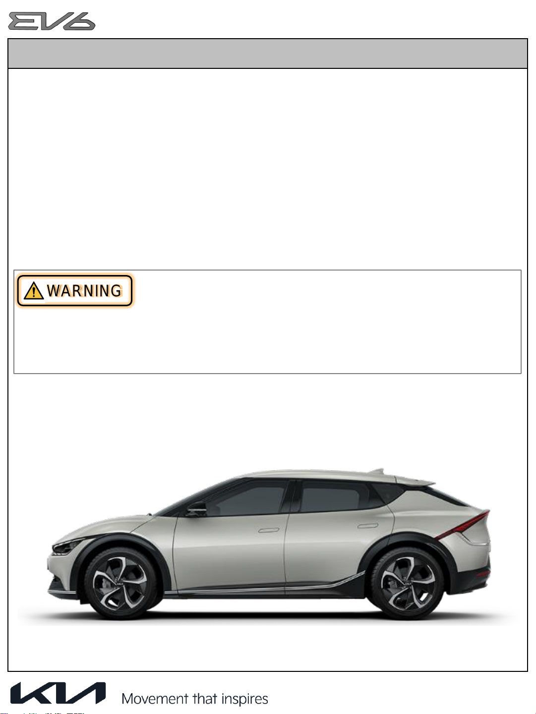
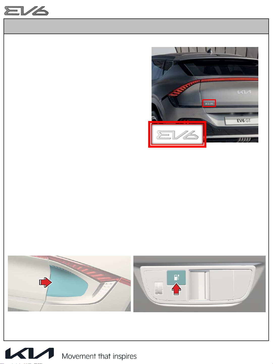
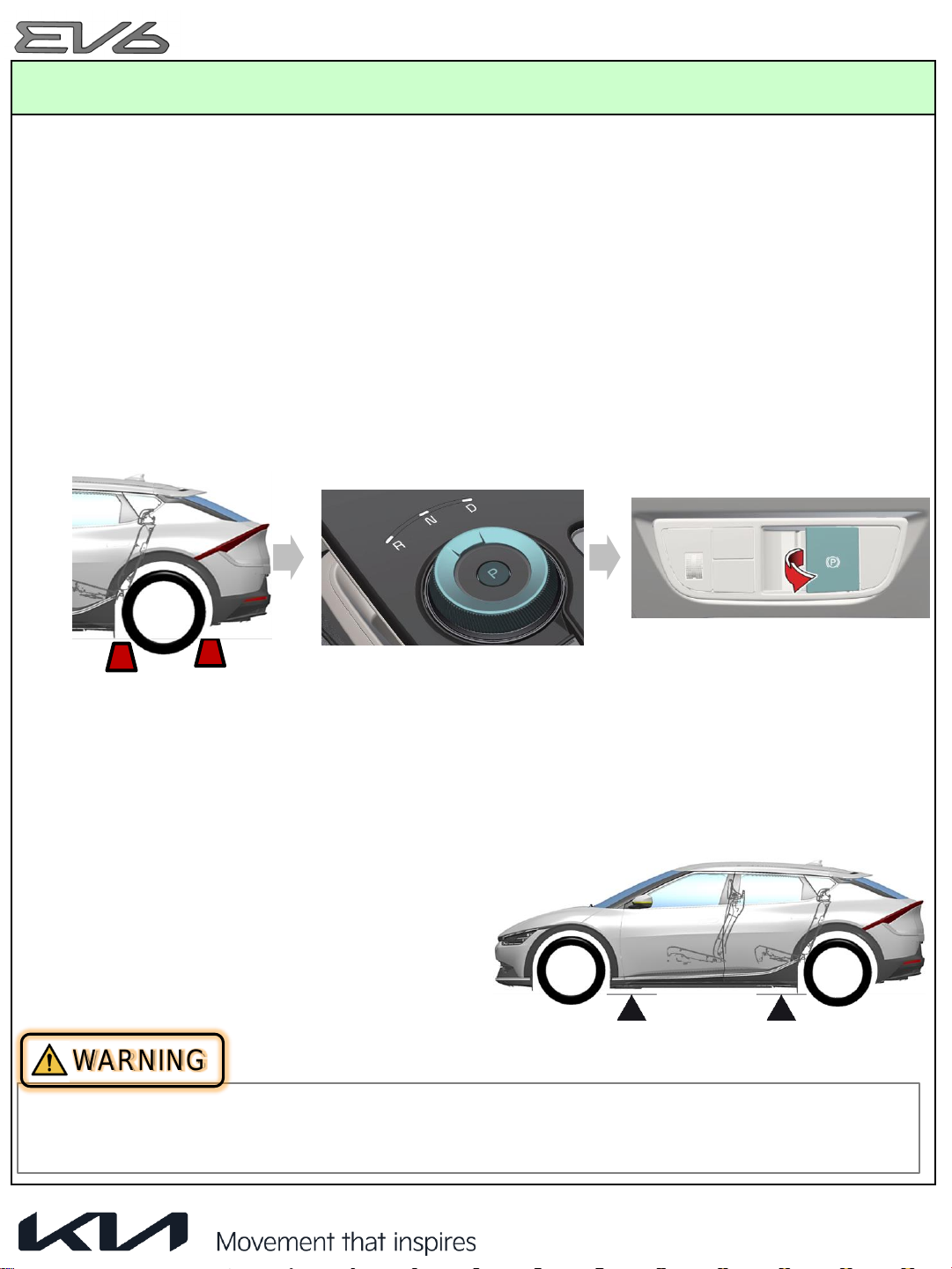
Kia EV6 2022 User manual

Emergency
Response
Guide
Version_1
1

1. Identification / Recognition
3
2. Immobilization / Stabilization / Lifting
7
3. Disable Direct Hazards / Safety Regulations
8
4. Access to the Occupants
13
5. Stored Energy / Liquid / Gases / Solids
17
6. In Case of Fire
21
7. In Case of Submersion
25
8. Towing / Transportation / Storage
26
9. ImportantAdditional Information
29
Contents
2

1. Identification / Recognition
Initial Response: Identify, Immobilize and Disable
Identify
•
The EV6 is an electric vehicle. Emergency responders should respond to emergency
scenarios involving the EV6 accordingly, exercising extreme care and caution to avoid
contact with the high voltage system within the vehicle.
The following procedures should be used whenever you are dealing with a EV6 at an
emergency scene. However, all operations should be consistent with your department’s
standard operating procedures, guidelines, and any applicable laws. When an EV is
damaged in a crash, the high voltage safety systems may have been compromised and
present a potential high voltage electrical shock hazard. Exercise caution and wear
appropriate personal protective equipment (PPE) safety gear, including high voltage safety
gloves and boots. Remove all metallic jewelry, including watches and rings.
3
WARNING

1. Identification / Recognition
1.1 Identifying a EV6
“EV6
” Car name emblem on Tailgate
•
The EV6 can be easily identified by the car
name emblem attached on the tailgate on the
left side.
•
The car name emblem may be missing or
hidden after a crash due to damage to the
vehicle. Always be sure to utilize additional
methods of identification before determining
that the vehicle is not a electric car.
Charging Port
•
The charging port is located on the rear right side.
#Note : The doors must be un
-locked to open the charge port door.
How to open the charging port
1.
Press the unlock door button, depress the brake pedal and apply the Electric Parking Brake
(EPB).
2.
Turn OFF all switches, move the shift lever to P (Park) and turn off the vehicle.
3.
Open the charging door by pressing it, or press the “charging door open button” in the crash
pad.
4

1. Identification / Recognition
1.1 Identifying a EV6
VIN Label
The VIN (Vehicle Identification Number) identifies
an electric car
with a “C” displayed in the
4th position, as shown in the below picture.
The VIN can be found:
1) VIN Plate also can be seen through the windshield from outside.
2) On the vehicle certification label attached to the driver’s side (or passenger) center pillar.
3) Underneath the front passenger seat (or driver seat).
XXXCXXXXXXXXXXXX
4th position (C)
5

1. Identification / Recognition
1.1 Identifying a EV6
The EV6 Cluster Instrument Panel displays
EV specific features such as high voltage
battery SOC (State of Charge) as below
.
EV6 Cluster Instrument Panel
Charge Status Indicator
The battery charge status indicator (4 lighted bars),located inside the charging door, is
illuminated when the vehicle is charged. The number of lights illuminated indicates the
charge level of the battery.
6
1. Speedometer
2. Distance to empty
3. Power/Charge gauge
4. Battery SOC (State of Charge)
5. LCD display
6. Warning and indicator lights
7. Reduction gear shift indicator
8. Odometer
9. Regenerative braking level indicator
10. Electric energy economy

2. Immobilization / Stabilization / Lifting
The next step is to immobilize the vehicle to prevent any accidental movement that can
endanger response personnel or civilians. When the EV6 is damaged in a crash, the vehicle
may appear to be shut off, even when it actually is not, due to a lack of engine sounds.
When the "READY" mode light is illuminated on the Instrument Panel, the vehicle can move
silently using the electric motor. Responders should approach the vehicle from the sides and
stay away from the front or rear as they are potential paths for vehicle movement. Be sure to
immobilize the vehicle in the following manner.
Chock the wheels
Set the Electronic Parking
Brake (EPB)
Put the vehicle in P (Park)
position by pressing the ‘P’
button on the rotary shifter
2.2 Vehicle Stabilization
Use standard stabilization (lift) points, as
shown beside.Always be sure to connect to a
structural component of the vehicle and avoid
placing cribbing under high voltage cables,
and other areas not normally considered
acceptable.
2.1 Immobilization
7
•
When installing a block or jack, avoid high voltage cable, high voltage battery.
•
If high voltage components or cables are exposed, do not place any support on them.
WARNING

3.
Disable Direct Hazards / Safety Regulations
The final step in the initial response process, conducted after immobilizing the vehicle, is to
disable the vehicle, its SRS components and the high voltage electrical system. To prevent
current flow through the system, use one of the following procedures to disable the vehicle.
3.1 Disabling the System – Smart Key System and “POWER”
START/STOP Button
1.
Confirm the status of the READY light on
the instrument panel. If the READY
light is illuminated, the vehicle is ON.
“POWER” START/STOP Button
a) If the READY light is NOT
illuminated, the vehicle is off. Do not
push the “POWER” START/STOP
button because the vehicle may start
(go
into READY mode).
b) To turn OFF the system, press the 'P' (Park) button on the rotary shifter dial, and
press the POWER button.
8
Case I
Power
Off
12V battery
disconnection
High voltage
shut off
Case II*
12V battery
disconnection
Fuse removal
(Fuse box)
High voltage
shut off
*In case of emergency

3.
Disable Direct Hazards / Safety Regulations
2. If necessary, lower the windows, unlock the doors and open the tail gate as required,
before disconnecting the 12V battery. Once the 12V battery is disconnected, power
controls will not operate.
3. Before disconnecting the 12V battery, turn OFF ignition and remove the smart key at
least 2 meters away from the vehicle to prevent accidental restart.
4. Open the hood and front trunk (A).
9
While depressing the brake pedal
Pressing POWER button Vehicle condition
One time Ready to drive
Without depressing
the brake pedal
Pressing POWER
button Vehicle condition
One time Electrical accessories are operational.
Two times The warning lights can be checked before the vehicle is started.
Three times Off
5. Open the 12V battery service cover (A).

3.
Disable Direct Hazards / Safety Regulations
6. Disconnect the 12 auxiliary battery negative (
-) terminal.
10
7. Pull up the yellow lever (interlock connector) to cut off the high voltage.
*The yellow lever doesn't get pulled out completely.

3.
Disable Direct Hazards / Safety Regulations
1. Open
the hood.
3.2 Disabling the System
–IG (Ignition) Fuse Removal
2. Remove the PE(Motor) room fuse box
cover.
3. If necessary, lower the windows,
unlock the doors and open the tailgate
as required, before disconnecting the
12V battery (located in the left side of
PE(Motor) room). Once the 12V battery
is disconnected, power controls will not
operate.
4. In the event the vehicle is unable
to be disabled using the “Power”
START/STOP Button, using the fuse
puller located in the PE(Motor) room
fuse box, pull both the IG1, IG2 fuse
from the PE(Motor) room fuse box. If
the IG fuses cannot be located, pull
out all of the fuses and relays in the
fuse box.
PE(Engine) room fuse box
11

3.
Disable Direct Hazards / Safety Regulations
If previously mentioned methods of disabling the vehicle’s system are unsuccessful, any
emergency
procedures involving the electric vehicle may cause the accidental
deployment of undeployed airbags and electric shock from high
-voltage components.
5. Disconnect the 12V battery and disable the high voltage battery by referring to page 9, 10.
•
Before engaging in any emergency response procedures, ensure the vehicle is
disabled and wait 5 minutes to allow the capacitor in the high voltage system to
discharge to avoid electrocution.
•Exposed cables or wires may be visible inside or outside the vehicle. Never touch
the metal chassis wires, cables, connectors, or any electric components before
disabling the system.
Failure to follow these instructions will lead to serious bodily injury
or death by
electrocution.
Electrocution Risk
12
WARNING

4. Access to the Occupants
4.1 Extraction Operations
The EV6 is an electric vehicle. Because of the high voltage components contained therein,
first responders should pay special attention when they extract occupants in the car. Before
performing any extraction operations, the first responders should
"Identify, Immobilize and
Disable"
the vehicle as discussed in sections on emergency procedures.
4.2 Vehicle Stabilization
Use standard stabilization (lift) points, as
shown beside.Always be sure to connect to a
structural component of the vehicle and avoid
placing cribbing under high voltage cables,
and other areas not normally considered
acceptable.
4.3 Extraction Tools and Procedure
When responding to an incident involving the EV6, we recommend that the first responders
follow their organization’s standard operating procedures for dealing with vehicle emergencies.
When the first responders cut the vehicle, they should always pay special attention to the
airbag system, orange colored high voltage cables and other high voltage components so that
the parts are not damaged and to prevent a risk of explosion or electrocution.
13
4.4 Door open
When the door outer handle doesn’t pop-up, push the front side inwards.

4. Access to the Occupants
4.5 Location of Ultra
-high Strength Steel
14
Mild steel
High
strength steel
Ultra
-high strength steel
In these images, high strength steel is used in the areas colored in blue and ultra
-high strength
steel is used in the red colored areas. Depending on the tools used, ultra
-
high strength steel can
be challenging or impossible to cut. If necessary, use a workaround technique.

4. Access to the Occupants
4.6 Occupants Rescue Guide
When dealing with an emergency situation, refer to the components as below.
# Do not cut the body near the airbag, high voltage cable, fuel system.
15
LHD
4WD, long-range model
Supplemental Restraint System
Control Module (SRSCM) Airbag Airbag Inflator
High voltage cable Air-conditioning line
Seat belt pretentioner
Fuse box (with the service plug that
can disable the high voltage system)
12V battery
Ultra-High Strength
Steel
High Voltage Battery
Air-conditioning
component High voltage c
omponent
12V battery (-) connector
High voltage charge p
ort

4. Access to the Occupants
4.6 Occupants Rescue Guide
When dealing with an emergency situation, refer to the components as below.
# Do not cut the body near the airbag, high voltage cable, fuel system.
16
Supplemental Restraint System
Control Module (SRSCM) Airbag Airbag Inflator
High voltage cable Air-conditioning line
Seat belt pretentioner
Fuse box (with the service plug that
can disable the high voltage system)
12V battery
Ultra-High Strength
Steel
High Voltage Battery
Air-conditioning
component High voltage c
omponent
12V battery (-) connector
High voltage charge p
ort
4WD, long-range model
RHD

5. Stored Energy / Liquid / Gases / Solids
5.1 High Voltage System
17
Rear motor
HV battery
PTC heater
Front HV junction block
Battery heater
Front inverter
and motor
A/C Comp
ICCU
HV junction block
Multi-inverter
Below illustration shows 4WD, Long-range model of EV6.
Charging port

5. Stored Energy / Liquid / Gases / Solids
5.1 High Voltage System
ICCU
18
Capacitor in Inverter
•
There is the capacitor inside the inverter. Wait 5+ minutes for the capacitor to discharge
after removing the service plug.
The ICCU, located under the 2nd-row seats, incorporates an On-Board
Charger (OBC)and Low Voltage DC-DC Converter (LDC).
- OBC : HV battery charging equipment that converts externalAC to DC, to
charge the high voltage battery.
- LDC : High voltage of battery is converted low voltage (DC 12V) through the
LDC for supplying power to electrical components.
Inverter
- Front (4WD only) : Inverter converts the DC voltage to an AC voltage to control the motor.
- Rear (Multi-Inverter) : The multi-inverter is an advanced charging system designed to allow
flexible charging with multiple voltage sources of 400 V and 800 V. In a 400 V charging
infrastructure, it boosts the voltage to 800 V via the motor and inverter and then uses the
boosted voltage to charge the 800 V battery. In a 800 V charging infrastructure, it uses
the high voltage sent from the charger to charge the battery.
Inverter (Front)
Multi-Inverter (Rear)
WARNING

5. Stored Energy / Liquid / Gases / Solids
5.1 High Voltage System
High Voltage Battery
The HV lithium
-ion polymer battery supplies and stores electric energy.
It is located under the EV6 chassis.
12V
Auxiliary Battery
The 12V auxiliary battery powers all of the vehicle’s standard
electronics like a radio, lights, door locks, power windows,
etc
. Also,
it powers the VCU(Vehicle Control Unit), VCMS (Vehicle Charging
Management System) which controls the high voltage current and
vehicle.
Motor
Type Interior Permanent Magnet Synchronous
Motor (IPMSM)
Max. Output (kW) Front : 70 / Rear: 160
Max Torque (Nm) Front : 255 / Rear: 350
Inverter
(Front/Rear) Input Voltage(V) 452.5~778.3
ICCU
OBC Max. Output(kW) 10.9
Output Voltage(V) DC 360~826
LDC Max. Output (kW) 1.8
Input Voltage(V) DC 360~826
High Voltage Battery
Type Lithium-ion polymer
Rated Voltage (V) Long-range : 697 / Economy : 523
Energy (kWh) Long-range : 77.4 / Economy : 58.0
Quantity for Pack
(Number of Modules) Long-range : 32 / Economy : 24
※
Specification
19

5. Stored Energy / Liquid / Gases / Solids
5.2 High Voltage Orange Cabling
The high voltage cabling is orange, per Society of Automotive Engineers (SAE) standards.
Cables run under the floor of the vehicle and connect the high voltage battery to the ICCU,
Motor, Inverter, Junction box, A/C compressor
and other high voltage components located
towards the front of the vehicle.
cablesYou can identifythe vehicle as an electric vehicle with the presence of orange
under the hood, in the under-floor battery compartment, or HV cables under thecar,
•Never cut or disconnect the high voltage orange cabling and connectors without
disabling the HV system by removing the safety plug (refer to page 8 to 10).
•Exposed HV cables or wires may be visible inside or outside the vehicle. Never touch
the metal chassis wires, cables, connectors, or any electric components before
disabling the system.
Failure to follow these instructions will lead to serious bodily injury or death by electrical
shock.
High Voltage Cables
20
WARNING
Other manuals for EV6 2022
2
Table of contents
Other Kia Automobile manuals

Kia
Kia Ceed 2017 User manual

Kia
Kia Sorento 2007 Parts list manual

Kia
Kia Sedona 2010 User manual

Kia
Kia Borrego 2010 User manual

Kia
Kia 2014 Optima Owner's manual

Kia
Kia Sorento 2005 User manual

Kia
Kia 2015 Cadenza Parts list manual

Kia
Kia Forte 2019 Assembly instructions

Kia
Kia EV/ Plug-in Hybrid User manual

Kia
Kia Niro 2017 User manual