KICK ASS KADCDC40A-AND User manual

®
DCDC CHARGER
WITH MPPT SOLAR CONTROLLER
USER MANUAL
KADCDC40A-AND
KADCDC20A-AND
V1.5

1
ŸTo avoid injury or damage to your vehicle ensure the instructions are read
carefully and understood.
ŸBatteries can produce harmful vapour and explosive gases when being
charged.
ŸEnsure batteries are mounted and stored in an area with good ventilation.
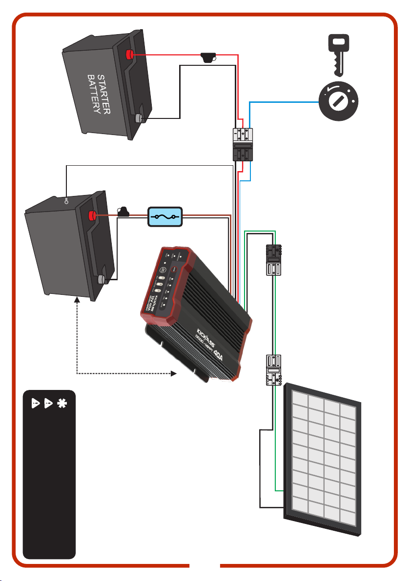
ŸAs this Charger has powerful output current, circuit protection such as fuses or
circuit breakers must be installed as near as possible to the batteries - refer to
wiring diagrams in this manual for correct fitting.
WARNINGS
This manual will give you all of the essential information you need to own and
operate your new KickAss 20/40A DCDC Charger with MPPT Solar Controller.
The purpose & features of the KickAss 20/40A DCDC Charger with MPPT Solar
Controller:
uCan charge multiple battery types:
Compatible with GEL, AGM, WET, CALCIUM or Lithium LiFePO4.
uPrevent your auxiliary battery from draining your start battery:
Built-in voltage sensing will ensure your start battery charges your auxiliary battery
when the vehicle is running. It will then disconnect the start battery from the
auxiliary battery when the vehicle is not running.
uEnsure your auxiliary battery is being fully charged and maintained:
Most modern vehicles (especially those manufactured after 2010) do not provide
the correct voltages and charge control to safely and completely charge your
auxiliary battery. The Charger overcomes this issue by boosting the charge voltage
to an optimal output level while ensuring your auxiliary battery is safely charged via
its multi-stage charge algorithm.
uWhen your vehicle is not charging, charge from the built-in MPPT solar
controller:
Maximum power point tracking is the most efficient type of solar controller and
allows you obtain the maximum amount of charge from your solar panels. When
your vehicle is not doing the charging, the built-in MPPT solar controller will let your
solar panels do the work.

2
Stay safe and protect your assets with these protective features:
„Short circuit protection
The Charger will not turn on unless the batteries are connected correctly.
„Reverse polarity protection
If you connect positive and negative the wrong way around the Charger will show a
fault.
„Over voltage protection
If the Charger detects voltages connected to its inputs or outputs that are too high it
will shut down.
„Over temperature protection
The Charger will lower its output current if it senses that the unit will overheat.
„Temperature compensation:
The included temperature sensor will measure the battery temperature and adjust
current accordingly to prevent overcharging.
For more technical details, specifications & videos please visit
kickassproducts.com.au

3
SPECIFICATIONS
Input Voltage Range
Efficiency
No Load Current Draw
Maximum Output Power
Maximum Continuous Charging Current
Maximum Input Current
Solar Input Voltage Range
Alternator Input Voltage Range
Ambient Operating Temperature
Charger Model KADCDC20A-AND KADCDC40A-AND
5-32V DC
9-32V DC
10-32V DC
27A
<15 mA
Approx. 93% when full load
20 °C to +80 °C
20A
300W
47A
40A
500W
OPERATING CONDITIONS
MECHANICAL
Certifications
IP Rating
Weights
Dimensions
IP66
154*120*44mm
870g
192*120*44mm
950g
BATTERY CAPACITY GUIDE
LiFePO4
Lead Acid ( WET,GEL,AGM,CAL) 80 – 200Ah
50 – 120Ah
200 – 500Ah
120 – 500Ah
BATTERY
Minimum Auxiliary Battery Voltage
Float Voltage
Absorption Voltage
Compatible Battery Type
INTERGRATED ISOLATOR CONTROL
Cut in / Cut out Voltage
(Ignition override OFF)
Input voltage
GEL WET AGM CAL LiFePO4
14.1V 14.4V 14.7V 15.3V 14.5V
13.5V 13.4V 13.6V
9V 0V
*30 SEC DELAY BEFORE THE CHARGER WILL CUT IN OR OUT
Cut in / Cut out Voltage
(Ignition override ON)
12V 24V
CUT IN
13.2V
CUT OUT
12.6V
CUT OUT
25.2V
CUT IN
26.4V
CUT IN
12.2V
CUT OUT
10.5V
CUT OUT
21.0V
CUT IN
24.4V
PROP65
Fuse Size 40A 60A

4
KADCDC20A-AND
DIMENSIONS

5
KADCDC40A-AND

6
Battery Type LEDs
Fault LED
Alternator LED
Solar LED
Mounting Slots 4.5mm
Charging Stage LEDs
Solar Priority Button
Battery Mode Button
Solar Priority LED
PRODUCT OVERVIEW

7
„The KickAss Charger has been engineered to charge 12 Volt GEL, AGM, WET,
CALCIUM or Lithium LiFePO only. Do not use this charger for any other purpose or
4
with any other battery types.
„Do not attempt to charge known faulty, damaged, frozen or broken batteries.
„Ensure charger is close to battery, however never mount the charger directly on the
battery.
„Ventilation is very important in battery charging, always ensure battery positioning is
in a well ventilated area to allow charging gases to dissipate.
„Keep sparks or flames away from batteries being charged as they could emit
explosive gases.
„Always check the batteries and charging system periodically to ensure no faults
occur.
„Ensure all cabling is secure and cannot be cut, broken or short circuited.
„Battery acid is corrosive. If acid comes into contact with skin or eyes, please seek
medical advice.
„Never connect this charger to mains supply.
„We recommend fitting a 50-75 amp fuse on both the input and output sides of the
charger such as the SKU: KAMAXIFHAND or SKU: KAFUSECOVER-KIT to protect
cables from short circuits etc.
MOUNTING
It is most important to mount your KickAss Charger as close as possible to your auxiliary
battery and be sure to keep your charger away from sources of heat. eg. Turbos and
exhaust pipes. This will ensure maximum performance out of your charger.
SAFETY FIRST!
INSTALLATION GUIDE

8
WIRING SIZE
To make sound electrical connections, the battery cable should be the correct size and the correct
terminals should be crimped or soldered.
Note:
• Always use a fuse in-line for all connections to the starter and aux battery!
• The input and output negative cables labeled Ground 3 and Ground 2 should be
connected at the battery negative poles for improved performance.
For more information or assistance, see installation videos at kickassproducts.com.au
CABLE SIZING
The table below outlining the required cable size for a given install length.
Please refer to this table for Vehicle Input, Solar Input, Ground and Battery Output cable thickness
requirements. Always choose a wire cross sectional area equal to or greater than what is specified
below.
Part Number
KADCDC20A-AND
KADCDC40A-AND
Cable Install Length
meter(m) feet(ft)
1 - 6.5
6.5 - 8
3 - 21
12 - 26
1 - 6.5 3 - 21
6.5 - 8 21 - 26
Recommended
Wire Cross
Section (mm²)
Closest
(BAE, B&S, AWG)
7.71
13.56
13.56
13.56
8
6
6
6
Recommend KickAss
Wiring Kit
KAPRDBWK8MMPP
KAHDDBWKPP80
KAHDDBWKPP65
KAHDDBWKPP80

9
WIRING DIAGRAM
NOTE: Ignition override used only if required
CAUTION: Check model specification for solar input
CAUTION: Always ensure fuses are installed
AUXILIARY
BATTERY
2
BLUE - IGNITION OVERRIDE 1.5mm
BLACK - TEMPERATURE SENSOR
KICKASS EXTENSION LEAD
SKU: KA8M10-A2A, KA8M2.5-A2A,
KA8M5.5-A2A
KICKASS INLINE
MAXIFUSE
- KAMAXIFHAND
MOUNT DC-DC CHARGER
AS CLOSE AS POSSIBLE
TO THE AUXILIARY BATTERY
SOLAR PANEL
SOLAR
ALT. IN
OUTPUT
i
i
Note: Refer to Cable Size
Table for KA recommended
wiring kit details

10
WIRING DIAGRAM - SOLAR PANEL ONLY
CAUTION: Check model specification for solar input
CAUTION: Always ensure fuses are installed
AUXILIARY
BATTERY
MOUNT DC-DC CHARGER
AS CLOSE AS POSSIBLE
TO THE AUXILIARY BATTERY
SOLAR PANEL
BLACK - TEMPERATURE SENSOR
KICKASS INLINE
MAXIFUSE
- KAMAXIFHAND
OUTPUT
SOLAR
I
KICKASS EXTENSION LEAD
SKU: KA8M10-A2A, KA8M2.5-A2A,
KA8M5.5-A2A

11
12V 20A
CHARGING STAGE PROFILE
BULK
ABSORPTION
FLOAT
GEL
100%
Current
Until
14.1 V
AGM
100%
Current
Until
14.7 V
WET
100%
Current
Until
14.4 V
CALCIUM
100%
Current
Until
15.3 V
LifePO4
100%
Current
Until
14.5 V
Constant
14.1 V
Until 2.6A
Constant
14.7 V
Until 2.6A
Constant
14.4 V
Until 2.6A
Constant
15.3 V
Until 2.6A
Constant
14.5 V
Until 2.6A
STAGE DESCRIPTION
The battery type setting must be confirmed during device installation. When the auxiliary
battery is connected, press and hold the Mode button for 2 ~ 4 seconds, upon releasing
the button, the battery type LED will move to the next position. Repeat the steps until
required battery type LED is selected. Battery type setting is now programed The
selected battery type will be saved as the new default.
NOTE:
When in FLOAT stage, the battery is fully charged. At float stage, when the battery voltage drops to
0.3V below the specified float voltage for the battery type connected, the charger will restart charging
form the BULK stage.
13.5V
at 100%
Current
Max
13.4V
at 100%
Current
Max
13.4V
at 100%
Current
Max
13.6V
at 100%
Current
Max
13.6V
at 100%
Current
Max
CHOOSING THE BATTERY TYPE

12
12V 20A12V 20A
12V 20A
12V 20A
Standby Mode
No inputs detected. Once the Aux battery has
been connected and is within the detectable
voltage range, the battery type LED will short flash
to indicate the device is in standby mode and no
input sources are detected
Battery type selection mode
Press and hold the Mode button for 2 ~ 4
seconds, upon releasing the button, the battery
type LED will move to the next position. Repeat
the steps until required battery type LED is
selected. Battery type setting is now programed
and charger will return to Standby mode after a
short time.
Standby Mode Alternator input detected
With no Solar connected or detected and the
Alternator is the only available input source, the
input LED will short flash to indicate input voltage
is below the set cut-in voltage. Charger is still in
Standby mode and has not begun to charge the
battery.
Standby Mode Alternator and Solar inputs
detected
Both input sources are detected but neither has
reached the set cut in voltage range. By default
Alternator input has priority and will provide power
to charge the battery. Solar priority has not been
selected and indicator LED is on.
Charging with Alternator or Solar only
Once the input source reaches the set cut-in voltage, charging will begin. The battery type LED
will turn solid and the active charge stage LED will come on and remain solid, while the input
source LED will continue to flash.
ALTERNATOR ONLY SOLAR ONLY
12V 20A
12V 20A
UNDERSTANDING SOLAR, ALTERNATOR
& CHARGING LIGHTS

13
12V 20A
12V 20A 12V 20A
12V 20A 12V 20A
Absorption Charge Stage
ALTERNATOR ONLY SOLAR ONLY
Float stage
Input source LED will change to a long flash sequence when charging stage transfers to float.
Battery is now fully charged.
ALTERNATOR ONLY SOLAR ONLY
Charging with Alternator as priority (default)
Once the Alternator input voltage reaches the set
cut-in voltage, charging can begin. The battery
type LED will turn solid and the active charge
stage LED will come on and remain solid, while
the input source LED will continue to flash. Solar
input LED will remain solid while source is
available. The charger will transition through the
different charging stages as previously shown,
until the battery is full.
Charging with Solar as priority - Setting Solar Priority mode
The function of Solar Priority mode is to allow the charger to check for available solar input before
choosing the alternator as the input source. To do this, the charger will assess the state of charge
of the battery and decide if the available solar can effectively supply enough charge or choose the
alternator as the best input source.
The Solar Priority function can be set at any time, once the Aux battery has been connected. To
set Solar Priority, press and hold Solar Priority button for 2 ~ 4 seconds, then realse the button, to
change the priority . The Solar Priority indicator LED will start to flash.
12V 20A
12V 20A

14
Lithium BMS Sleep Mode & Recovery Feature:
Most lithium batteries are built with a Battery Management System (BMS) inside to
protect the battery from over charging, over discharging and extreme temperature
changes.
One of the key functions of the BMS is to protect your battery by internally disconnecting
the load¹ when voltage drops below specific parameters, this will then result in the battery
entering into a “sleep” mode.
¹ (Load includes any accessories and/or device/s drawing charge from the battery. Eg:
fridges, pumps, food sealers, etc)
The KickAss DCDC MPPT Solar Battery Controller has a lithium battery recovery
function. This function has been designed to recover lithium batteries from a sleep mode.
Lithium Battery Recovery Mode Procedure
First disconnect any load connected to the lithium battery. Secondly connect Alternator
Input or Solar Input to the KickAss DCDC Charger with MPPT Solar Controller. Thirdly
connect the output from the DCDC charger to the lithium battery. When the DCDC
Charger with MPPT Solar Controller input charging voltage reaches the relevant cut in
voltage, the DCDC Charger with MPPT Solar Controller will automatically try to activate
the battery every minute. When DCDC Charger with MPPT Solar Controller attempts to
activate the battery, if a open-circuit or short-circuit error is detected, the DCDC Charger
with MPPT Solar Controller will enter standby mode until the next activation attempt. If
the activation attempt is successful, DCDC Charger with MPPT Solar Controller will
initiate the regular three stage charging sequence.
Once the DCDC Charger with MPPT Solar Controller indicates the battery has reach the
FLOAT charge state, the battery has been fully recovered and loads reconnected.

15
If the fault light is flashing, please refer to the fault codes below for diagnostics.
Note: Only the selected battery type LED will flash when the device detects a fault condition.
Alternator
(green)
Solar
(green)
Battery
Type
(green)
Solar
Priority
(Green)
Fault
(red) Fault Solution
Over voltage
detected at
alternator input
Check alternator
battery voltage
Over voltage
detected at
solar input
Check solar
panel open circuit
voltage
Over voltage
detected at
output
Check auxiliary
battery voltage
Over temperature
Let the unit cool down
for some time or
improve ventilation
12V 20A
FAULT CODES

16
The following table provides some additional fault finding advice should any potential issues arise
with the system installation, or unexpected system behavior is identified afer normal operation.
Alternator
(green)
Solar
(green)
Battery
Type
(green)
Solar
Priority
(Green)
Fault
(red) System Behavior Recommended Troubleshooting
Procedure
No voltage detected
at alternator and
solar input
§Check alternator and solar
panel voltages.
§Check system wiring for
potential connection issues.
Low voltage
detected at
alternator input
(Voltage is below
cut-in range)
§Check alternator battery
voltage.
§Check system wiring for
potential connection issues.
§Check alternator operation.
§Check solar panel voltage.
§Check system wiring for
potential issues.
§Check alternator battery
voltage.
§Check system wiring for
potential connection issues.
§Check alternator operation.
§Check solar panel voltage.
§Check system wiring for
potential issues.
Low voltage
detected at solar
input
(Voltage is below
cut-in range)
Low voltage
detected at
alternator or solar
input
(Voltage is below
cut-in range)
TROUBLESHOOTING

17
This device complies with part 15 of the FCC Rules. Operation is subject to the
following two conditions: (1) this device may not cause harmful interference, and (2)
this device must accept any interference received, including interference that may
cause undesired operation.
Note: This equipment has been tested and found to comply with the limits for a Class
B digital device, pursuant to part 15 of the FCC Rules. These limits are designed to
provide reasonable protection against harmful interference in a residential installation.
This equipment generates, uses, and can radiate radio frequency energy and, if not
installed and used in accordance with the instructions, may cause harmful
interference to radio communications. However, there is no guarantee that
interference will not occur in a particular installation.
If this equipment does cause harmful interference to radio or television reception,
which can be determined by turning the equipment off and on, the user is encouraged
to try to correct the interference by one or more of the following measures:
ŸReorient or relocate the receiving antenna.
ŸIncrease the separation between the equipment and receiver.
ŸConnect the equipment to an outlet on a circuit different from that to which the
receiver is connected.
ŸConsult the dealer or an experienced radio/TV technician for help.
Changes or modifications to this product not authorized by KickAss could void the
electromagnetic compatibility (EMC) and wireless compliance and negate your
authority to operate the product.
This product has demonstrated EMC compliance under conditions that included the
use of compliant peripheral devices and shielded cables between system
components. It is important that you use compliant peripheral devices and shielded
cables between system components to reduce the possibility of causing interference
to radios, television sets, and other electronic devices.
Exposure to radio frequency energy. The radiated output power of this device
meets the limits of FCC/IC radio frequency exposure limits. This device should be
operated with a minimum separation distance of 20 cm (8 inches) between the
equipment and a person’s body.
FCC COMPLIANCE STATEMENT

18
KickAss constantly updates
frequently asked questions,
troubleshooting, videos and
specifications, please visit:
kickassproducts.com.au
for the most up to date
information.
NEED HELP?

19
THANK YOU FOR CHOOSING
DC-DC CHARGERS
kickassproducts.com.au
For more informaon please visit us at:
This manual suits for next models
1
Table of contents
Other KICK ASS Batteries Charger manuals

KICK ASS
KICK ASS KADCDC25A User manual

KICK ASS
KICK ASS KACHG1222 User manual

KICK ASS
KICK ASS KACHG1220 LI-ION User manual

KICK ASS
KICK ASS KADCDC25A-AND User manual

KICK ASS
KICK ASS KACHG1207 User manual

KICK ASS
KICK ASS KACHG128 User manual

KICK ASS
KICK ASS KADCDC20A-CAR User manual

KICK ASS
KICK ASS KICKCHARGE 10K User manual