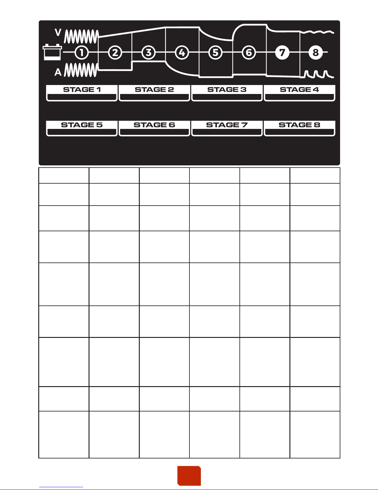
KICK ASS KACHG1207 User manual

8-STAGE AUTOMATIC
MODELS: KACHG1207, KACHG1212, KACHG1220, KACHG2410
Instruction Manual
Please read user manual carefully before use.
BATTERY CHARGER
MCU CONTROLLED - HIGH FREQUENCY SWITCHMODE

◆Before using the charger, please read and understand the instructions.
◆Provide adequate ventilation and prevent sparks and flames around charging
area. Explosive gases may escape from the battery during charging.
◆Designed For charging 12 Volt or 24 Volt Lead Acid, AGM,Gel and Calcium
batteries ONLY.
◆Disconnect the 240V AC mains supply before making or breaking
the connections to the battery.
◆The battery charger must be plugged into an earthed socket-outlet.
◆Designed for indoor use only. Do not expose to rain or moisture.
◆Connection to mains supply is to be in accordance with National wiring rules.
◆If the AC cord is damaged do not attempt to use charger. It must be replaced
or repaired by a qualified person.
◆Do not attempt to charge non-rechargeable batteries.
◆Corrosive substances may escape from the battery during charging and
damage delicate surfaces. Store and charge in a suitable area.
◆Never charge a frozen battery.
◆Ensure vehicle engine, ignition and accessories including lights, appliances
etc are turned off prior to charging.
◆This appliance is not intended for use by young children or any person with
limited capabilities (mental and physical) unless they have been adequately
supervised by a responsible person to ensure that they can use the appliance
safely.
◆Please store disconnected and out of reach of unsupervised children
WARNING
8-STAGE AUTOMATIC CHARGING
This is a fully automatic battery charger featuring 8 charging stages
Automatic charging is proven to provide your battery with an optimal charge and
maintenance sequence that will also protect your battery from being overcharged.
This allows you to leave the charger connected to the battery indefinitely if required.
8-stage charging is a very a c curate and comprehensive charging process that
will result in a better battery performance with a longer life expectancy. This is
evident when comparing to the use of more traditional chargers.
8-stage chargers are suitable for most battery types including WET, Calcium,
Maintenance Free, AGM, and GEL batteries. They may also help restore drained
and sulphated batteries.
1
FEATURES 2
1

The 8-Stages Include:
30 mins or 4 hrs
depending on
battery voltage
(Calcium model
must enter
Recondition stage)
GEL AGM WET CALCIUM REFERENCE
11V / 22V 11V / 22V 11V / 22V Max 8h
2
SOFT START
11V / 22V
5
ANALYSE
3
BULK
8
MAINTAIN
1
DESULPHATION
6
RECONDITION
4
ABSORPTION
7
FLOAT
100%
Current until
14.1V / 28.2V
Constant
14.1V / 28.2V
until current
drops to 15%
Checks if
voltage holds
at 13.2V / 26.4V
Constant
current (15%)
limited to
14.1V / 28.2V
13.7V/27.4V
100% Current
During 12.6V-
14.1V/25.2V-
28.2V , the
current control
at 100%~20%
100%
Current until
14.4V / 28.8V
Constant
14.4V / 28.8V
until current
drops to 15%
Checks if
voltage holds
at 13.2V / 26.4V
Constant
current (15%)
limited to
14.4V / 28.8V
13.7 V/27.4V
100% Current
During 12.6V-
14.4V/25.2V-
28.8V , the
current control
at 100%~20%
100%
Current until
14.7V / 29.4V
Constant
14.7V / 29.4V
until current
drops to 15%
Checks if
voltage holds
at 13.2V / 26.4V
Constant
current (15%)
limited to
16V / 32V
13.7V/27.4V
100% Current
During 12.6V-
14.7V/25.2V-
29.4V , the
current control
at 100%~20%
50% Current
until 12.5V / 25V
100%
Current until
14.7V / 29.4V
Constant
14.7V / 29.4V
until current
drops to 15%
Checks if
voltage holds
at 13.2V / 26.4V
Constant
current (15%)
limited to
16V / 32V
13.7V/27.4V
100% Current
During 12.6V-
14.7V/25.2V-
29.4V , the
current control
at 100%~20%
Max 8h
Max 24h
30 minutes
90sec
10 days
charge cycle
Charge cycle
restarts if
voltage drops
50% Current
until 12.5V / 25V
50% Current
until 12.5V / 25V
50% Current
until 12.5V / 25V
TIME
(12V / 24V) (12V / 24V) (12V / 24V) (12V / 24V)
BULK CHARGE
ALLOWS THE FULL VOLTAGE / CURRENT
OUTPUT OF THE CHARGER REQUIRED BY
THE BATTERY (DEPENDING ON THE
CHEMISTRY MODE SELECTED)
SOFT START
STARTS THE CHARGING
PROCESS GENTLY TO ENSURE
AN EVEN FLOW ACROSS EACH CELL BEFORE
INCREASING THE CHARGE RATE
DESULPHATION
REMOVES BUILT
UP SULPHATE DEPOSITS STORED
ON THE INTERNAL PLATES
ABSORPTION
AUTOMATICALLY REDUCES
THE CURRENT OUTPUT WHILST MAINTAINING
THE REQUIRED VOLTAGE (DEPENDING
ON THE CHEMISTRY MODE SELECTED)
ANALYSIS
CHARGER WILL
PERFORM A QUICK BATTERY
TEST TO ENSURE THE BATTERY
CAN HOLD IT’S CHARGE
RECONDITION
BOOSTS THE
BATTERY BY INCREASING THE
VOLTAGE WITH A REDUCED
CURRENT OUTPUT TO BRING THE
BATTERY TO IT’S FULL STATE
CHARGED
BATTERY IS FULLY CHARGED
AND CAN BE SAFELY DISCONNECTED.
ALTERNATIVELY, THE BATTERY CAN
REMAIN CONNECTED TO THE
CHARGER INDEFINITELY WITHOUT
OVERCHARGING
MAINTAIN
AFTER THE CHARGED STAGE
THIS STAGE WILL SUPPLY A PULSE CYCLE
TO SAFELY MAINTAIN THE BATTERY FOR
EXTENDED PERIODS OF TIME. IF CONNECTED
FOR 10 DAYS OR MORE WITHOUT
INTERRUPTION, THE LED WILL ILLUMINATE.
Desulphation - Soft Start - Bulk - Absorption - Analyse - Recondition - Float - Maintain
2

Desulphation
The Desulphation stage is designed to break down sulphation that occurs in batteries that have been
left discharged for extended periods of time, this process assists in revitalizing the battery.
Sulphation occurs when lead-sulphate hardens and clogs up the battery cells.
Soft Start
A preliminary charge process that reduces the initial current into the battery. This protects the battery
from any high start up current from the charger and increases battery life and performance.
Bulk (Maximum Current)
Chargers the battery with the rated maximum output current until approximately 80% capacity. This
stage continues until the battery's terminal voltage has risen above the set limit (depending on
battery type). If the terminal voltage has not reached the set voltage limit within the pre-set time, the
charger switches to fault mode (Stage 3 LED solid) and discontinues the charging process. If so, the
battery is faulty or its capacity is too large.
Absorption (Constant Voltage)
This stage ensures the battery reaches a fully charged state by gradually reducing the current and
maintaining a constant voltage until the battery is 100% charged.
◆ 12V charger: If the voltage is below 13.2 volts (fail), the charger will initiate the Recondition stage.
◆ 12V charger: If the voltage is above
13.2 volts (pass), the charger will proceed to the Float Stage.
◆ 24V charger: If the voltage is below 26.4 volts (fail), the charger will initiate the Recondition stage.
◆ 24V charger: If the voltage is above 26.4 volts (pass), the charger will proceed to the Float Stage.
Analyse
An automatic battery test is conducted immediately after the absorption stage. This test monitors the
battery voltage for 90 seconds to determine if the charge was successful.
Recondition
This stage is automatically introduced if the battery is unable to hold a charge after the Analysis
Stage. The Recondition Stage can recover batteries from a deeply discharged state, rejuvenating the
output capacity and extending the battery life.
The Recondition stage will run for 4 hours and at the end will conduct a test to determine if the
battery is now holding charge. If the battery fails this test the charger will display a fault.
Float
The Float Stage maintains the fully charged state without overcharging or damaging the battery. This
means the charger can be left connected to the battery indefinitely. The battery is fully charged and
can be disconnected at this stage.
Maintain
Designed to maintain the battery at 95-100% capacity over extended periods of time. The charger
monitors the battery voltage and gives a Maintain when necessary to remove plate sulphation and
keep the battery fully charged. This Maintain cycle is repeated infinitely over a 10 day period if left
connected. If the terminal voltage drops below the set level or is disconnected, the charger
automatically goes back to the beginning of the charging cycle.
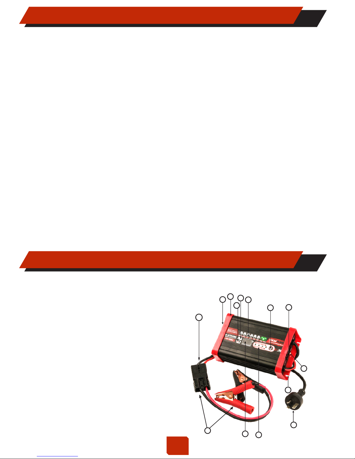
Featuring the latest technology in battery chargers, switch mode chargers convert 240V AC power to
12V/24V DC power using electronic components unlike traditional battery chargers that rely on
heavy transformers. This allows the charger to be light weight and compact without sacrificing
performance.
SWITCHMODE TECHNOLOGY 3
3

POLARITY PROTECTION
Prevents the output leads from sparking due to accidental reverse connection or short
circuit, making the charger safer to use around batteries.
OUTPUT SHORT PROTECTION
Short circuit connection of the clips: Check clips are not touching each other OR
Check the clips are correctly connected to the battery.
NON BATTERY LINK PROTECTION
If battery charger connects with a non battery load, it will go into protection state.
DISCONNECT PROTECTION
The charger has entered the energy save mode. This happens if the charger is not
connected to the battery within 2 minutes.
OVER VOLTAGE PROTECTION
The 12V charger will automatically supply protection if the voltage is higher than 17.5V. The
24V charger will automatically supply protection if the voltage is higher than 35V.
OVER TEMPERATURE PROTECTION
This occurs if the internal temperature is above 65OC +/-5 OC
COOLING FAN
The charger is fitted with a thermostatically controlled fan to cool on-board electronics
and maintain charging performance. The cooling fan will engage automatically when
there is a high load on the battery or there is sufficient heat build up.
The 8-stage utomatic harg consists of the following components:A Battery C er
1. Mode button (Press/Hold).
2. Stage LED status display indicates.
power, charging and fully charged.
3. Power LED.
4. Fault LED.
5. Output Voltage Display.
6. Battery type LED.
7. Quick Connect Adaptor.
8. 240VPower Cord.
9. Thermostatically controlled cooling fan.
10. Ground terminal.
11. Mounting flange.
12. Ventilation Grill.
13. 3.5mm mounting hole.
14. DC Output Lead.
12
8
56
9
2
13
10
11
4
3
1
7
14
PROTECTIVE FEATURES 4
PRODUCT OVERVIEW 5
4

The 'Charging' and 'Stage' LED's will illuminate and flash in various patterns
to indicate the different Stages of Charging.
See the table below for Flashing / Solid patterns.
Note: SOLID : FLASH OFF : :
Output Polarity Reverse
Protection
Over Voltage Protection
Disconnect Protection
Is seriously sulphated
Will not accept charge
Faulty Battery
Battery Fully Charged
Thermal Protection
Power Off
Power On
1. Desulphation
2. Soft Start
3. Bulk
4. Absorption
6. Recondition
7. Float
Stage
5. Analyse
8. Maintain
Non Battery Link Protection
Output Short Protection
Fully Charged
(LED)
(Stage 3 LED)
(Stage 2 LED)
(Stage 1 LED)
00.0
- U -
- t -
Battery
Voltage
00.0
Output
Voltage
POWER ON LED STAGE LED FAULT LED FAULT LED
CHARGE STATUS INDICATOR 6
5

Stage LED: illuminates and flashes when 8-stage charging is in progress and
illuminates solid when fully charged. (Stage 7/8)
POWER ON LED
If the 'Power' LED is illuminated with a:
1. SOLID LIGHT
The mains cable is connected to the wall socket.
2. FLASHING LIGHT
The charger has entered the energy save mode. This happens if the
charger is not connected to the battery within 2 minutes.
FAULT LED - Solid Light
If the fault LED is illuminated solid, check the following:
Has charging been Interrupted in Stage 1, 2, or 3?
Restart the charger by pressing the MODE-button (Press/Hold).
If charging is still being Interrupted, the battery:
STAGE 1: ...is seriously sulphated and may need to be replaced.
STAGE 2: ...can not accept charge and may need to be replaced.
STAGE 3: ... battery is faulty and may need to be replaced. (Bulk charging
has timed out and stopped after 24 hours).
FAULT LED - Flashing Light
Charger's Internal Temperature is higher than 65°C +/-5°C. Please turn off
and disconnect charger and let it cool down.
Ensure there is adequate ventilation when charging.
6

Constant voltage until
8-Stage automatic
Maintain charge up to 11V
50% current rating up to 12.5V
13.7V also with Maintain feature
65O C +/-5 O
C
Monitors voltage for 90 seconds
App.85%
The 12V charger will automatically supply protection if the voltage is higher than 17.5V.
Most types of lead acid batteries including WET, MF, Calcium, AGM, and GEL
KACHG1207 - 12 Volt 7 Amp
215W
12V DC
7A
2V
250VAC, T3.15A
50 - 100Ah
1.05Kg
current drops to 1.05A
197 x 116 x 62mm
P/No.
CHARGE CONTROL
Charger Type
Input Voltage
Input Power
Output Voltage
Output Current
Minimum Start Voltage
Back Drain
Current Fuse Rating
Desulphation
Soft Start
Bulk
Absorption
Recondition
Float
Maintain
Efficiency
Thermal Protect
Ambient Temperature
Over Voltage Protection
BATTERY RANGE
Deep Cycle
Types of Batteries
Dimension (L×W×H)
Weight
Analyse
1mA
7A up to 14.1V (GEL) 14.4(AGM) 14.7V(WET) 14.7V(CALCIUM)
12.6V- 14.1V,7-2A (GEL)
12.6V- 14.4V,7-2A (AGM)
12.6V- 14.7V,7-2A (WET)
12.6V- 14.7V,7-2A (CALCIUM)
Constant current (1.05A)
for 30 mins or 4 hours
limited to:
14.1V (GEL)
14.4(AGM)
16V(WET)
16V(CALCIUM)
Cooling Fan Automatic temperature controlled
Specifications are subjected to change without prior notice.
220-240V / 50Hz
-20
C to + 50
C, output power is reduced automatically at high temperatures
O
O
Certifications
SPECIFICATIONS - KACHG1207 7
7

Monitors voltage for 90 seconds
Specifications are subjected to change without prior notice.
KACHG1212 - 12 Volt 12 Amp
8-Stage automatic
12V DC
1mA
Maintain charge up to 11V
50% current rating up to 12.5V
13.7V also with Maintain feature
65O C +/-5O C
90 - 150Ah
1.1Kg
332W
12A
2V
250VAC, T3.15A
App.85%
-20O C to + 50O
C, output power is reduced automatically at high temperatures
The 12V charger will automatically supply protection if the voltage is higher than 17.5V.
Most types of lead acid batteries including WET, MF, Calcium, AGM, and GEL
P/No.
CHARGE CONTROL
Charger Type
Input Voltage
Input Power
Output Voltage
Output Current
Minimum Start Voltage
Back Drain
Current Fuse Rating
Desulphation
Soft Start
Bulk
Recondition
Float
Maintain
Efficiency
Thermal Protect
Ambient Temperature
Over Voltage Protection
BATTERY RANGE
Deep Cycle
Types of Batteries
Dimension (L×W×H)
Weight
Analyse
197 x 116 x 62mm
12A up to 14.1V (GEL) 14.4(AGM) 14.7V(WET) 14.7V(CALCIUM)
12.6V- 14.1V,12-2A (GEL)
12.6V- 14.4V,12-2A (AGM)
12.6V- 14.7V,12-2A (WET)
12.6V- 14.7V,12-2A (CALCIUM)
Constant current (1.8A)
for 30 min or 4 hours
limited to:
14.1V (GEL)
14.4(AGM)
16V(WET)
16V(CALCIUM)
Cooling Fan Automatic temperature controlled
Constant voltage until
current drops to 1.8A
Absorption
220-240V / 50Hz
Certifications
SPECIFICATIONS - KACHG1212 8
8

Constant voltage until
Monitors voltage for 90 seconds
Specifications are subjected to change without prior notice.
8-Stage automatic
Maintain charge up to 11V
50% current rating up to 12.5V
13.7V also with Maintain feature
65O C +/-5O C
App.85%
-20O C to + 50O
C, output power is reduced automatically at high temperatures
The 12V charger will automatically supply protection if the voltage is higher than 17.5V.
Most types of lead acid batteries including WET, MF, Calcium, AGM, and GEL
P/No.
CHARGE CONTROL
Charger Type
Input Voltage
Input Power
Output Voltage
Output Current
Minimum Start Voltage
Back Drain
Current Fuse Rating
Desulphation
Soft Start
Bulk
Recondition
Float
Maintain
Efficiency
Thermal Protect
Ambient Temperature
Over Voltage Protection
BATTERY RANGE
Deep Cycle
Types of Batteries
Dimension (L×W×H)
Weight
Analyse
20A up to 14.1V (GEL) 14.4(AGM) 14.7V(WET) 14.7V(CALCIUM)
current drops to 3A
12.6V- 14.1V,20-2A (GEL)
12.6V- 14.4V,20-2A (AGM)
12.6V- 14.7V,20-2A (WET)
12.6V- 14.7V,20-2A (CALCIUM)
150 - 300Ah
217 x 116 x 62mm
1.28Kg
KACHG1220 - 12 Volt - 20 Amp
554W
12V DC
20A
2V
250VAC, T5A
1mA
Constant current (3A)
for 30 min or 4 hours
limited to:
14.1V (GEL)
14.4(AGM)
16V(WET)
16V(CALCIUM)
Cooling Fan Automatic temperature controlled
Absorption
220-240V / 50Hz
Certifications
SPECIFICATIONS - KACHG1220 9
9

Specifications are subjected to change without prior notice.
P/No.
8-Stage automatic
Maintain charge up to 22V
50% current rating up to 25V
27.4V also with Maintain feature
CHARGE CONTROL
Charger Type
Input Voltage
Input Power
Output Voltage
Output Current
Minimum Start Voltage
Back Drain
Current Fuse Rating
Monitors voltage for 90 seconds
App.85%
The 24V charger will automatically supply protection if the voltage is higher than 35V.
Most types of lead acid batteries including WET, MF, Calcium, AGM, and GEL
KACHG2410 24 Volt 10 Amp
547W
24V DC
10A
4V
250VAC, T5A
70 - 130Ah
1.28Kg
Constant voltage until
current drops to 1.5A
217 x 116 x 62mm
Desulphation
Soft Start
Bulk
Absorption
Recondition
Float
Maintain
Efficiency
Thermal Protect
Ambient Temperature
Over Voltage Protection
BATTERY RANGE
Deep Cycle
Types of Batteries
Weight
Analyse
1mA
10A up to 28.2V (GEL) 28.8(AGM) 29.4V(WET) 29.4V(CALCIUM)
25.2V- 28.2V,10-2A (GEL)
25.2V- 28.8V,10-2A (AGM)
25.2V- 29.4V,10-2A (WET)
25.2V- 29.4V,10-2A (CALCIUM)
Constant current (1.5A) for
30 min or 4 hours limited to:
28.2V (GEL)
28.8(AGM)
32V(WET)
32V(CALCIUM)
Cooling Fan Automatic temperature controlled
220-240V / 50Hz
65O C +/-5O C
Dimension (L×W×H)
-20O C to + 50OC, output power is reduced automatically at high temperatures
Certifications
SPECIFICATIONS - KACHG2410 10
10

Settings are made by pressing the MODE-button (Press/Hold). After about two
seconds the charger activates the selected program. The selected program will
automatically default to the AGM Mode next time the charger is connected
STEP 1 – CHECK THE ELECTROLYTE LEVEL
Please ensure to check the electrolyte level prior to charging the battery by
removing the vent caps (not required on sealed & maintenance free batteries.The
electrolyte level should be 6mm (1/4") above the battery's plates. If low, use
distilled water to top up to the correct level and refit the vent caps.
STEP 2A – CONNECTING TO BATTERY OUT OF VEHICLE
Connect the RED Output Lead (Battery Clip from the charger to the Positive (+)
Battery Terminal) and ensure a good connection is made.
Connect the BLACK Output lead (Battery Clip from the charger to the Negative (-)
Battery Terminal) and ensure a good connection is made.
Alternatively if connecting via the Chargers Output Plug, make sure the external
plugs polarity is correct before connecting.
Connection out of vehicle
RED BLACK
STEP 2B – CONNECTING TO THE BATTERY IN VEHICLE
Before connecting, determine if the vehicle is Negative (-) or Positive (+) Earthed.
Negative earthed vehicles are most common and use the chassis as an Earth by
connecting the Battery Negative Terminal to a conductive chassis point.
The purpose of connecting the charger through the chassis is to eliminate any
power spikes going through the vehicles sensitive electrical system.
If you are unsure, please seek advice from a qualified person before connecting.
OUTBACK PROOF GEAR
GEL AGM WET CAL
HOLD
PRESS
12 VOLT
BATTERY TYPE
POWER ON/OFF
SMART/AUTOMATIC
CHARGED
654321
maintainrecondanalyseabsorption
bulk
soft start
desulphation
7 8
BATTERY
CHARGER
CHARGING INSTRUCTIONS 11
11

Connect the BLACK Output Lead (Battery Clip) from the charger to the Negative (-)
Battery Terminal and ensure a good connection is made.
Connect the RED Output Lead (Battery Clip) from the charger to a clean conductor
point on the vehicle's chassis away from any fuel lines or moving parts.
Connect the RED Output Lead (Battery Clip) from the charger to the Positive (+)
Battery Terminal and ensure a good connection is made.
Connect the BLACK Output Lead (Battery Clip) from the charger to a clean
conductor point on the vehicle's chassis away from any fuel lines or moving parts.
Connection in vehicle
(negative earthed)
BLACK
RED
Connection in vehicle
(positive earthed)
BLACK
RED
OUTBACK PROOF GEAR
GEL AGM WET CAL
HOLD
PRESS
12 VOLT
BATTERY TYPE
POWER ON/OFF
SMART/AUTOMATIC
CHARGED
654321
maintainrecondanalyseabsorption
bulk
soft start
desulphation
7 8
BATTERY
CHARGER
OUTBACK PROOF GEAR
GEL AGM WET CAL
HOLD
PRESS
12 VOLT
BATTERY TYPE
POWER ON/OFF
SMART/AUTOMATIC
CHARGED
654321
maintainrecondanalyseabsorption
bulk
soft start
desulphation
7 8
BATTERY
CHARGER
.
NEGATIVE EARTHED CONNECTION (Most Vehicles) 12
POSITIVE EARTHED CONNECTION 13
12

The chassis earthing terminal should be connected to an earting point which
will be depending on where the battery charger is installed. In a vehicle,
connect the chassis ground terminal to the chassis of the vehicle. In a boat,
connect to the boat's grounding systems. In a fixed location, connect to an
earth stake. This connection is not essential but may increase efficiency.
STEP 3 - CONNECT TO 220-240V AC MAINS POWER
Connect the battery charger to a certified 220-240V AC mains powered
socket and turn on the mains power.
STEP 4 - CHARGING PROCESS
During the charge process, the 'Charging' and 'Stage' LED's will flash various
patterns. This is normal and indicates the various charging stages. Refer to
"How do I know what stage the battery charger is in" in the FAQ section, page 18.
When the 'Stage' LED remains on (this is known as the Float Stage) the
charger can be left connected to the battery indefinitely without over charging.
Alternatively, the battery can be disconnected at this point as it is fully charged.
If the 'Power On' LED is flashing, there is a fault; refer to "Fault Codes"
explanation on page 17 of this manual.
STEP 5 DISCONNECTING THE CHARGER FROM BATTERY
Ensure the 220-240V AC mains switch is turned off and the charger is disconnected
from the 220-240V AC mains power.
Battery out of vehicle:
Remove the BLACK Output Lead (Battery Clip) from the Negative (-) Battery Terminal.
Remove the RED Output Lead (Battery Clip) from Positive (+) Battery Terminal.
Battery in vehicle
Remove the Output Lead (Battery Clip) from the chassis connection.
Remove the Output Lead (Battery Clip) from the Battery Terminal.
OUTPUT
12V DC
INPUT
AC
8-STAGE AUTOMATIC CHARGING
INPUT: 220-240V AC, 50/60Hz, 554W
OUTPUT: xxV DC, xxAmps
FUSE: T5A, 250V AC
FAN
CHASSIS
GND
CHASSIS EARTHING (Not Essential) 14
13

This 8-stage charger is designed for indoor use only and not outdoor conditions
(rain and moisture). Ensure that both the charger and battery are in a well-
ventilated area during charging.
If permanently fixed, the charger should be mounted to a suitable vertical or
horizontal panel, with at least 10cm clearance from the end plates to provide
adequate ventilation for the cooling fan.
The battery charger is molded with end plates that include a mounting flange
for easy mounting.
MOUNTING INSTRUCTIONS 15
14

If required, It is possible to hard wire the DC charging Output Leads to the battery
for permanent installations.
You will need an Adaptor Lead with Ring Terminals, Fuse, Fuse Holder and a
suitable Plug to attach to the current Charger Plug.
Alternatively, if you would like to install this yourself please follow the steps below:
1. Cut off the supplied battery clips; ensure you leave sufficient cable to reach the
battery terminals. (DO NOT extend the battery charger DC output cables, as the
added voltage drop will cause incorrect charging).
2. Fit a ring terminal to the BLACK Negative (-) wire.
3. Connect the In-line fuse to the RED Positive (+) wire.
4. Connect a ring terminal to the other end of the in-line fuse.
5. Connect the RED Output Lead (with in-line fuse and ring terminal) to the Positive
(+) battery post.
6. Connect the BLACK lead (with ring terminal) to the Negative (-) Battery Terminal.
7. Fit the correctly rated fuse. (Recommended: Double the chargers current rating)
If the charger is used in a Permanent / Hard Wired application and the vehicle
will not be used for extended periods of time, it is best to leave the charger
connected to mains power (turned 'On') so that it can maintain and keep the
the battery fully charged.
Ensure any modification to the 220-240V AC mains lead is carried out
by a qualified person and that connection to mains supply is in accordance
with the National wiring rules.
Inline fuse
RED BLACK
Ring terminal
OUTBACK PROOF GEAR
GEL AGM WET CAL
HOLD
PRESS
12 VOLT
BATTERY TYPE
POWER ON/OFF
SMART/AUTOMATIC
CHARGED
654321
maintainrecondanalyseabsorption
bulk
soft start
desulphation
7 8
BATTERY
CHARGER
PERMANENT WIRING TO BATTERY 16
15

Please Note:
It is recommended to use a charger with an output of at least 10% of your total
Battery Amp Hour Capacity.
(Example - 120Ah Battery is Recommended to have at least a 12 Amp Charger)
CHARGERBATTERY SIZE
7 Amp
12V
50 - 100 Ah
12 Amp
12V
90 - 150 Ah
20 Amp
12V
150 - 300 Ah
10 Amp
24V
70 - 130
CHARGING TIME
7-24 Hours
7-24 Hours
7-24 Hours
7-24 Hours
SKU
KACHG1207
KACHG1212
KACHG1220
KACHG2410
CHARGER REFERENCE : 12 / 24 VOLT BATTERY 17
16

The 8 Stage Charger Technology features high quality internal sensing components to
determine any issues with the battery or charger. Various Fault Codes will be displayed
on the charger for reference.
The Fault Codes will be displayed in the following way:
O O
65 C +/-5 C
Error Code
Fault
Cause Remedy
Reverse Polarity
/ Output Short
Short circuit or
reverse
connection of the
clips
Check clips are not
touching each other
OR Check the clips are
correctly connected to
the battery.
Non Battery
Link Non battery link
Please choose the
correct battery type for
connection.
Over Voltage
12V battery:
Voltage is above
17.5V.
24V battery:
Voltage is above
35V.
Over
Temperature
Internal
Temperature
is above
Turn off charger
and allow to cool.
Ensure there is
adequate
Ventilation
Faulty
Battery
Bulk charging
has timed out
and stopped after
24 hours.
Battery is faulty and
may need to be
replaced. Please
get tested by a
Qualified Person
Disconnect the
charger and check
the battery voltage.
This charger is
suitable for 12V or
24V Batteries only.
Power On
LED
Stage
Stage 3
(LED)
Charger is NOT a
Power Supply.
LED LED
FAULT CODES 18
17

Desulphation Soft Start Bulk Absorption Recondition Float
123456 7
Stage
Analyse Maintain
8
Q. How do I know if the battery is charged?
A. The charger's 'Charged' and/or 'Maintain' LED (Stage 7/8) will be illuminated (solid). Alternatively
use a Battery Hydrometer (if caps are removable). A reading of 1.250 or more in each cell indicates a
fully charged battery.
Q. I have connected the charger properly but the 'STAGE LED'
does not come on?
A. In some cases, batteries can be discharged to the point where they have very little or no voltage
(Not recommended and may void warranty). This can occur if a small amount of power is used for a
long time, for example: An interior light is left on for an extended period of time or an electrical
appliance without a 'voltage cut-out' is unknowingly connected.
Q. What minimum voltage will the charger need to sense?
A. Although a battery is not designed to be discharged below 10.5 Volts (12 Volt System) and 21
Volts (24 Volt System) under load, the 8-Stage chargers are designed to charge from as little as 7.0
Volts (12V charger) and 14.0 Volts (24V charger). If the battery voltage is lower than this, use a pair of
booster cables to connect an external battery with the same voltage in parallel. This should provide
more than the required volts to the battery being charged. The charger can then start to charge the
battery and the booster cables can be removed.
Q. Can I use the charger as a power supply?
A. 8-Stage chargers are designed to supply power to the battery clips Only, when they are connected
correctly to a battery. This is to prevent sparks during connection to the battery or if connected
incorrectly by mistake. This safety feature prevents the charger from being used as a 'Power Supply'.
No Voltage will be present at the clips until connected to the battery.
Q. How do I know what stage the battery charger is in?
A. Below are the conditions that are displayed by the 'Stage' LED for each of the charge stages:
Q. What if i have a question that has not been answered?
A. Please contact the supplier for any further questions or advice.
FREQUENTLY ASKED QUESTIONS 19
18

ALWAYS PLACE THE BATTERY CHARGER IN AN ENVIRONMENT
WHICH IS:
A. WELL VENTILATED.
B. NOT EXPOSED TO DIRECT SUNLIGHT OR HEAT SOURCE.
C. OUT OF REACH FROM CHILDREN.
D. AWAY FROM WATER / MOISTURE, OIL OR GREASE.
E. AWAY FROM ANY FLAMMABLE SUBSTANCE.
F. SECURE WITH NO RISK OF FALLING.
The charger is designed for charging 12V or 24V Lead-Acid, AGM, Gel and
Calcium Batteries. Do not use the charger for any other purpose.
◆ Check the charger cables prior to use. Ensure that no cracks have occurred in the cables or in
the battery clips. A charger with damaged cables or clips must not be used. A damage cable or
clip must be replaced by a professional representative.
◆ Never charge a damaged battery.
◆ Never charge a frozen battery.
◆ Never place the charger on top of the battery when charging.
◆ Always allow for adequate ventilation during charging.
◆ Avoid covering the charger.
◆ A battery being charged could emit explosive gases. Prevent sparks close to the battery. When
batteries are reaching the end of their life-cycle internal sparks may occur.
◆ All batteries fail sooner or later. A battery that fails during charging is normally taken care of by
the charger's advanced control, but some rare errors in the battery could still exist. Don't leave any
battery during charging unattended for an extended period of time.
◆ Ensure that the cabling is not obstructed or come into contact with hot surfaces or sharp edges.
◆ Battery acid is corrosive. Rinse immediately with water if acid comes into contact with skin or
eyes, seek immediate medical advice.
◆ Batteries consume water during use and charging. For batteries where water can be added, the
water level should be checked regularly. If the water level is low, add distilled water.
◆ This appliance is not designed for use by children or people who cannot read or understand the
manual unless they are under the supervision of a responsible person to ensure that they can use
the battery charger safely. Store and use the battery charger out of the reach of children, and
ensure that children cannot play with the charger.
◆ Connection to the mains supply must be in accordance with the national regulations for electrical
installations.
australiandirect.com.au
From the Team,
Thank You For Your Purchase!
CAUTION 20
SAFETY 21
This manual suits for next models
3
Table of contents
Other KICK ASS Batteries Charger manuals

KICK ASS
KICK ASS KADCDC40A-AND User manual

KICK ASS
KICK ASS KADCDC25A-AND User manual

KICK ASS
KICK ASS KICKCHARGE 10K User manual

KICK ASS
KICK ASS KACHG128 User manual

KICK ASS
KICK ASS KADCDC20A-CAR User manual

KICK ASS
KICK ASS KACHG1222 User manual

KICK ASS
KICK ASS KADCDC25A User manual

KICK ASS
KICK ASS KACHG1220 LI-ION User manual
Popular Batteries Charger manuals by other brands

Sony
Sony BCG-34HS operating instructions

Grape Solar
Grape Solar GS-100-KIT Quick connect guide

Hanna Instruments
Hanna Instruments HI 710040 instruction manual

Infinite Peripherals
Infinite Peripherals INFINEA BLUEPAD quick start guide

Guest
Guest 2606A Operation manual

Schumacher Electric
Schumacher Electric XC75 owner's manual