Kicker KS350 User manual

KS
KSCOAXIALSPEAKER
AND3-WAYSYSTEM
KS6930, KS690, KS680, KS650, KS600
KS5250, KS4100, KS460,KS400, KS350
©2007 Stillwater Designs
English Version
Versión Español
Sistema de 3 canales y altavoz coaxial KS
Manual del Propietario
Deutsche Version
KS-Koaxiallautsprecher und Dreiweg-System
Benutzerhandbuch
Version Française
Haut-parleur coaxial KS et système trois voies
Manuel d'utilisation
2008 KS Coax 4in1 a01.qxp 11/29/2007 3:54 PM Page 1

Your KS coaxials were specially designed for “Livin’ Loud” out in the harsh automotive
environment. They are made of advanced materials and construction techniques to
maintain optimal performance for years to come.
Application
The Kicker KS coaxial speakers are specifically designed for mounting in free-air
applications. The speakers do not require a sealed enclosure for optimum performance.
It is important to isolate the sound coming off the front of the driver from the sound
radiating from the back of the driver. This isolation is usually accomplished by using the
driver in a factory speaker location, or in a location with a semi-isolated rear chamber.
See Figure 1.
Location
The sound produced by the KS coaxials is directional. Find the best location for
stereophonic sound. If necessary, add more KS coaxial speakers to the system to help
distribute and balance the sound. After determining the best mounting locations, carefully
check the areas where the mounting hardware will be placed. See Figure 2.
INSTALLATION
Congratulations on your
KICKER purchase
Please record your purchase
information and keep your sales
receipt for validation of warranty.
Authorized Kicker Dealer:
Purchase Date:
Speaker Model Number:
_________________________
_________________________
_________________________
Please allow two weeks of break-in time for the speaker to reach optimum performance.
2
INSTALLATION
KSCoaxialSpeaker
Owner’sManual
KS6930 /KS690 /KS680 /KS650 / KS600
KS5250 /KS4100 /KS460 /KS400 / KS350
Models:
Mounting
If you are replacing factory speakers in their original locations, you may have to enlarge the
speaker cut-outs and pre-drill new screw holes using a 7/64” (2.5mm) bit. Custom mounting
locations will require more preparation and work. In either case, make sure the speaker will
not interfere with the trunk and door opening and closing mechanisms, and the enclosed
screws will not puncture the fuel tank, wiring, or interfere with any other mechanical parts on
the underside of the mounting surface. Cycle the windows all the way down and up.
If the speaker cut-out locations require you to cut metal, avoid structural metal and braces.
If the door body and panel cannot support the weight of the speaker, an optional reinforcing
ring (thin piece of wood or Medium Density Fiberboard) may be fastened or adhered to the
door body. Mount the speaker to the vehicle as outlined in Figure 2.
If factory speaker wiring is not available in your desired location, it may be necessary to run
speaker wire through the door jamb. The speaker wire should be kept away from sharp
edges and avoid the possibility of getting pinched by the door. An existing grommet in the
door jamb is the ideal place to run the
speaker wire. If the factory hole and
grommet do not exist or are inaccessible,
you must drill a hole to run the speaker
wire through the door jam. Be careful not
to drill into other wiring or door
mechanisms. Any time a wire is run
through a hole, it is necessary to insert a
rubber or plastic grommet to protect the
wire from damage as outlined in Figure 3.
If the supplied hardware is not applicable
to your installation, some other means of
securely attaching the speakers to the
vehicle must be used.
Figure 1
KSCOAXIALSPEAKER
Rear Seat
Trunk / Storage SpaceRear Sound
Waves
Front Sound
Waves
Figure 2
DoorPanel
Screw mounting ring and coaxial driver into speaker
cut-outand attach speaker grille.
DoorBody
Reinforcing Ring
(Optional)
Coaxial
Driver Speaker
Grille
Screws
Stagger theholes forthewiring and use arubber or
plastic grommet to protectthewire from damage.
Speaker
cut-out
Speaker
cut-out
Figure 3
Front Door
Body
Front Dash
Kick Panel
Speaker
cut-out
To the
amplifier or
sourceunit
3
Mounting
Ring
Note: TheKS5250mounting
ring attaches over thefront of
thewoofer. All other KSCoaxial
models attach as shown in
Figure 2.
2008 KS Coax 4in1 a01.qxp 11/29/2007 3:54 PM Page 2

4 5
PERFORMANCE
Wiring to a single channel
Hooking up the supplied wires to your Kicker KS-Series Coax Speakers is easy. One end of
each wire is terminated with a large and a small connector. The larger connector is crimped
to the gray wire and connects to the larger positive terminal of the speaker. The smaller
connector is crimped to the black wire and connects to the smaller negative terminal of the
speaker. The other end of these wires connects to your source unit or amplifier with the four
(4) included red butt crimp-down style connectors. The gray wire connects to the positive
output of the amplifier or source unit. The black wire connects to the negative output of the
amplifier or source unit. These connections can also be made with solder and heat shrink or
electrical tape to prevent electrical shorting of the speakers. See Figure 4.
Figure 4
KSCOAXIALSPEAKER
Other channel
KS-Series Coax Speaker
wired to asingle channel
SourceUnit orAmplifier
Note: All specifications and performance figures are subject to change. Please visit the www.kicker.com for the most current information.
To get the best performance from your new Kicker speakers, we recommend using genuine Kicker Accessories and Wiring.
Wiring two KS-Series Coax Speakers to a single channel
Modern high performance coaxial speakers have a lower DC Resistance than what used to
be available. The Kicker KS-Series Coax Speakers are rated at four ohms and work with any
source unit or amplifier designed to operate at a four ohm load. If you want to use two KS-
Series Coax Speakers on each channel of your source unit or amplifier wire the speakers in
series, as shown above. This will improve the sound quality, lower the total harmonic
distortion and lessen the thermal load at the source unit or amplifier. This may prevent an
amplifier from shutting down, due to over-current protection circuitry.
SourceUnit orAmplifier
Two KS-Series Coax Speakers
wired in series to asingle channel
Figure 5
INSTALLATION
Insert and crimp wire using
included red butt connectors to
connectspeaker wire to thewire
from sourceunit oramplifier.
Series
Wiring
Model:
Speaker Design
Woofer Size, in (mm)
Tweeter Size, in (mm)
Rated Impedance, ohm
DC Resistance, ohm
Power Range, Watts RMS
Peak Power Handling, Watts
Sensitivity [SPLo], dB @ 1W, 1m
Effective Frequency Range, Hz
Mounting Hole Diameter, in (mm)
Top Mount Depth, in (mm)
Bottom Mount Depth, in (mm)
Tweeter Protrusion, in (mm)
Specifications common to all models:
Tweeter Magnet Material - Neodymium
Tweeter Dome Material - Kaladex
Tweeter Design - Balanced Dome
Woofer Cone Material - Polypropylene
Woofer Surround Material - Santoprene
If you have any questions about the installation of your Kicker KS-Series Coax Speakers, see the Authorized Kicker Dealer where you made your
purchase. For more advice on installation, click on the SUPPORT tab on the Kicker homepage, www.kicker.com. Choose the Technical Support
tab, choose subject you are interested in, and then download or view the corresponding information. Please E-mail support@kicker.com or call
Technical Services (405) 624-8583 for specific or unanswered questions.
KS400
2 - Way
4 (100)
1/2 (13)
4
3
6-30
60
88
60-20k
3 11/16 (94)
1 13/16 (46)
2 1/16 (52)
1/8 (3.2)
KS460
2 - Way
4x6 (100x150)
1/2 (13)
4
3
6-30
60
88
50-20k
5 3/4 x 3 1/2 (146x89)
1 13/16(46)
2 (51)
1/16 (1.6)
KS4100
2 - Way
4x10 (100x250)
1/2 (13)
4
3
6-35
70
88
45-20k
3 7/8 x 9 5/16 (98x237)
2 7/16 (62)
2 3/4 (70)
0 (0)
KS5250
2 - Way
5 1/4 (130)
3/4 (20)
4
3
6-45
135
90
45-21k
4 9/16 (116)
2 (51)
2 1/4 (57)
1/16 (1.6)
KS350
2 - Way
3 1/2 (89)
1/2 (13)
4
3
6-20
40
88
80-20k
3 3/16 (81)
1 9/16 (40)
1 7/8 (48)
1/4 (6.4)
Performance
Pro Tip: You are one Kicker Loaded-Subwoofer enclosure, one ZX
Mono-Amplifier and a few cables away from a slammin’ system!
The Kicker ZX line of mono-amplifiers make it easy to upgrade to
solid bass with your existing or stock source unit. Please ask your
dealer about the Kicker Comp and CompVR Subwoofer upgrades.
2008 KS Coax 4in1 a01.qxp 11/29/2007 3:54 PM Page 3

KSCOAXIALSPEAKER
67
INSTALACIÓN
PERFORMANCE
Model:
Speaker Design
Woofer Size, in (mm)
Tweeter Size, in (mm)
Rated Impedance, ohm
DC Resistance, ohm
Power Range, Watts RMS
Peak Power Handling, Watts
Sensitivity [SPLo], dB @ 1W, 1m
Effective Frequency Range, Hz
Mounting Hole Diameter, in (mm)
Top Mount Depth, in (mm)
Bottom Mount Depth, in (mm)
Tweeter Protrusion, in (mm)
Specifications common to all models:
Tweeter Magnet Material - Neodymium
Tweeter Dome Material - Kaladex
Tweeter Design - Balanced Dome
Woofer Cone Material - Polypropylene
Woofer Surround Material - Santoprene
If you have any questions about the installation of your Kicker KS-Series Coax Speakers, see the Authorized Kicker Dealer where you made your
purchase. For more advice on installation, click on the SUPPORT tab on the Kicker homepage, www.kicker.com. Choose the Technical Support
tab, choose subject you are interested in, and then download or view the corresponding information. Please E-mail support@kicker.com or call
Technical Services (405) 624-8583 for specific or unanswered questions.
Performance
KS600
2 - Way
6 (160)
3/4 (20)
4
3
6-65
195
90
43-21k
5 (127)
1 15/16 (49)
2 1/4 (57.2)
3/16 (4.8)
KS650
2 - Way
6 1/2 (165)
3/4 (20)
4
3
6-65
195
90
40-21k
5 5/8 (143)
2 1/8 (54)
2 3/8 (60)
3/16 (4.8)
KS6930
3 - Way
6x9 (150x230)
3/4 (20)
4
3
6-100
300
92
30-21k
6x8 9/16(152x217)
3 3/16 (81)
3 5/8 (92)
5/8 (15.9)
KS680
2 - Way
6x8 (150x200)
3/4 (20)
4
3
6-60
180
90
45-21k
5x7 (127x178)
2 3/8 (60)
2 3/4 (70)
0 (0)
KS690
2 - Way
6x9 (150x230)
1 (25.4)
4
3
6-90
270
92
30-21k
6x8 9/16(152x217)
3 3/16 (81)
3 5/8 (92)
0 (0)
Pro Tip: You are one Kicker Loaded-Subwoofer enclosure, one ZX
Mono-Amplifier and a few cables away from a slamm’in system!
The Kicker ZX line of mono-amplifiers make it easy to upgrade to
solid bass with your existing or stock source unit. Please ask your
dealer about the Kicker Comp and CompVR Subwoofer upgrades.
Sus altavoces coaxiales KS han sido especialmente diseñados para vivir a todo volumen
Livin’ Loud™ en el riguroso ambiente automovilístico. Estos altavoces han sido
construidos con materiales y técnicas de construcción avanzados para mantener un
rendimiento óptimo durante muchos años.
Aplicación
Los altavoces coaxiales KS de Kicker han sido diseñados específicamente para
montarlos en aplicaciones al aire libre. Los altavoces no necesitan tener una caja sellada
para dar un rendimiento óptimo. Es importante separar el sonido radiado por delante del
sonido radiado por detrás del excitador. Esta separación se logra normalmente
instalando el excitador en una ubicación preestablecida de fábrica para el altavoz o en
una ubicación con una cámara trasera semiaislada. Vea la Figura 1.
Ubicación
El sonido producido por los altavoces coaxiales KS es direccional. Busque la mejor
ubicación para el sonido estereofónico. Si es necesario, agregue altavoces coaxiales KS
al sistema para distribuir y equilibrar el sonido. Después de determinar las mejores
ubicaciones de montaje, revise cuidadosamente los lugares en que va a instalar los
soportes de montaje. Vea la Figura 2.
¡Felicidades por su
compra de KICKER
Por favor registre su información de compra
y mantenga su recibo de ventas para
validación de la garantía.
Distribuidor autorizado
de Kicker:
Fecha de compra:
Número de modelo
del altavoz:
_________________________
_________________________
_________________________
Deje pasar aproximadamente dos semanas para que el altavoz alcance su rendimiento óptimo.
Altavoz coaxial KS
Manual del propietario
KS6930 /KS690 /KS680 /KS650 / KS600
KS5250 /KS4100 /KS460 /KS400 / KS350
Modelos:
Figura 1
Asiento trasero
Cajuela / Espacio de
almacenamiento
Ondas de
sonido traseras
Ondas desonido
delanteras
2008 KS Coax 4in1 a01.qxp 11/29/2007 3:54 PM Page 4

Montaje
Si va a cambiar los altavoces de fábrica sin cambiar su ubicación original, puede ser
necesario agrandar los cortes para altavoz y hacer nuevos agujeros piloto con una broca de
7/64 de plg. (2.5 mm). Las ubicaciones de montaje personalizado requieren más
preparación y trabajo. En cualquier caso, asegúrese de que el altavoz no interfiera con los
mecanismos de apertura y cierre de la puerta y de la cajuela y de que los tornillos que se
incluyen no perforen el tanque de gasolina ni rompan el cableado ni interfieran con ninguna
otra pieza mecánica debajo o detrás de la superficie de montaje. Suba y baje
completamente los vidrios de las ventanas.
Si la ubicación de los cortes para altavoz exige cortar metal, evite cortar los refuerzos o el
metal estructural. Si el panel y la estructura de la puerta no soportan el peso del altavoz, se
puede fijar o adherir un anillo de refuerzo opcional (pieza de delgada madera o Plancha de
Fibra de Densidad Media {Medium Density Fiberboard, MDF}) a la estructura de la puerta.
Monte el altavoz en el vehículo como se indica en la Figura 2.
Si no hay cableado de fábrica para altavoz en el lugar deseado, puede ser necesario
encaminar el cable que se incluye a través de la jamba de la puerta. Este cable debe
mantenerse alejado de los bordes afilados para que la puerta no pueda aplastarlo por
accidente. La arandela de goma que
pueda haber en la jamba de la puerta es el
lugar ideal para hacer pasar los cables de
altavoz. Si no hay agujero con arandela de
goma de fábrica, o el que hay es
inaccesible, es necesario hacer un agujero
para pasar los cables de altavoz por la
jamba de la puerta. Tenga cuidado de no
dañar otros cables o mecanismos de la
puerta. Cada vez que se hace pasar un
cable a través de un agujero, es necesario
insertar una arandela de plástico o de
goma para proteger el cable, como se
muestra en la Figura 3.
Si los tornillos que se incluyen no sirven
para su instalación, debe fijar firmemente
la caja al vehículo de alguna otra manera.
Figura 2
Panel dela puerta
Atornille el anillo demontajey el excitadorcoaxial en
el corte dealtavoz y fijela rejilla dealtavoz
Estructura
dela puerta
Anillo derefuerzo
(opcional)
Excitador
coaxial Rejilla de
altavoz
Tornillos
Escalone losagujerospara el cableado y protejael
cable conarandelas degomao plástico.
Corte para
altavoz
Corte para
altavoz
Figura 3
Estructura de
la puerta
Tablero de
instrumentos
Panel
interno
Corte para
altavoz
Hacia el
amplificadoro la
unidad fuente
Anillo de
montaje
Nota: Elanillo demontajedel
modelo KS5250se fijapor
delante del woofer. Todoslos
otrosmodelosdealtavoces
coaxiales KSse fijan como se
muestra en la Figura 2.
ALTAVOZCOAXIALKS
Cableado a un solo canal
Es fácil conectar los cables que se suministran a los altavoces coaxiales de la serie KS de
Kicker. El extremo de cada cable termina en un conector grande y un conector pequeño. El
conector grande está engarzado en el cable gris y se conecta a la terminal positiva grande
del altavoz. El conector pequeño está engarzado en el cable negro y se conecta a la
terminal negativa pequeña del altavoz. El otro extremo de estos cables se conecta a su
unidad fuente o amplificador con los cuatro (4) conectores tubulares de engarce rojos que
se incluyen. El cable gris se conecta a la salida positiva del amplificador o unidad fuente. El
cable negro se conecta a la salida negativa del amplificador o unidad fuente. Estas
conexiones también se pueden hacer con soldadura y encogedor térmico o cinta aislante
para evitar cortocircuitos en los altavoces. Vea la Figura 4.
Figura 4
Otro canal
Altavoz coaxial dela serie KS
cableado aunsolo canal
Unidad fuente o amplificador
Nota: Todas las especificaciones y cifras de rendimiento están sujetas a cambios.
Visite www.kicker.com para obtener la información más actual.
Para obtener el mejor rendimiento de sus nuevos altavoces Kicker, le recomendamos que use accesorios y cableado Kicker auténticos.
Dos altavoces coaxiales de la serie KS cableados a un solo canal
Los altavoces coaxiales modernos de alto rendimiento tienen menos resistencia a la CC que
los de antes. Los altavoces coaxiales de la serie KS de Kicker tienen un valor nominal de 4
ohms y funcionan con cualquier unidad fuente o amplificador diseñado para funcionar con 4
ohms de carga. Si desea utilizar dos altavoces coaxiales de la serie KS en cada canal de su
unidad fuente o amplificador, conecte los altavoces en serie, como se muestra arriba. Esto
mejora la calidad del sonido, reduce la distorsión armónica total y disminuye la carga
térmica en la unidad fuente o amplificador. Esto puede evitar que el amplificador se apague
a causa del circuito de protección contra exceso de corriente.
Unidad fuente o amplificador
Dosaltavoces coaxiales dela serie KS
cableadosen serie aunsolo canal
Figura 5
Inserte y engarcecables conlos
conectores tubulares rojospara
conectar cable dealtavoz al cable
proveniente dela unidad fuente o del
amplificador.
Cableado
en serie
INSTALACIÓN
INSTALACIÓN
8 9
2008 KS Coax 4in1 a01.qxp 11/29/2007 3:54 PM Page 5

Modelo:
Diseño del altavoz
Tamaño del woofer, plg. (mm)
Tamaño del tweeter, plg. (mm)
Impedancia nominal, ohms
Resistencia a la CC, ohms
Intervalo de potencia, W RMS
Procesamiento máximo de potencia, W
Sensibilidad [SPLo], dB a 1 W, 1 m
Gama efectiva de frecuencias, Hz
Diámetro del agujero de montaje, plg. (mm)
Profundidad de montaje por arriba, plg. (mm)
Profundidad de montaje por abajo, plg. (mm)
Protuberancia del tweeter, plg. (mm)
Especificaciones comunes a todos los modelos:
Material del imán del tweeter - Neodimio
Material del domo del tweeter - Kaladex
Diseño del tweeter - Domo equilibrado
Material del cono del woofer - Polipropileno
Material de la envolvente del woofer - Santoprene
Si tiene preguntas sobre la instalación de sus altavoces coaxiales de la serie KS de Kicker, vaya al distribuidor autorizado de Kicker donde los
compró. Si necesita más consejos sobre la instalación, haga clic en la lengüeta SUPPORT de la página Web de Kicker, www.kicker.com. Escoja la
lengüeta Technical Support (apoyo técnico), escoja el tema que le interese y luego transfiera o vea la información correspondiente. Envíe un
mensaje por correo electrónico a support@kicker.com o comuníquese con Servicios Técnicos llamando al (405) 624-8583 si tiene preguntas
específicas o a las cuales no ha encontrado respuesta.
KS400
2 canales
4 (100)
1/2 (13)
4
3
6-30
60
88
60-20k
3 11/16 (94)
1 13/16 (46)
2 1/16 (52)
1/8 (3.2)
KS460
2 canales
4 x 6 (100 x 160)
1/2 (13)
4
3
6-30
60
88
50-20k
5 3/4 x 3 1/2 (146 x 89)
1 13/16(46)
2 (51)
1/16 (1.6)
KS4100
2 canales
4 x 10 (100 x 250)
1/2 (13)
4
3
6-35
70
88
45-20k
3 7/8 x 9 5/16 (98 x 237)
2 7/16 (62)
2 3/4 (70)
KS5250
2 canales
5 1/4 (130)
3/4 (20)
4
3
6-45
135
90
45-21k
4 9/16 (116)
2 (51)
2 1/4 (57)
1/16 (1.6)
KS350
2 canales
3 1/2 (89)
1/2 (13)
4
3
6-20
40
88
80-20k
3 3/16 (81)
1 9/16 (40)
1 7/8 (48)
1/4 (6.4)
Rendimiento
Sugerencia profesional: A usted le falta nada más una caja de subwoofer cargado
Kicker, un monoamplificador ZX y unos cables para tener un sistema atronador. La
línea ZX de monoamplificadores Kicker facilita el mejoramiento a bajos sólidos con su
unidad fuente estándar o actual. Pregúntele a su distribuidor por los mejoramientos
de subwoofer Comp y CompVR de Kicker.
Modelo:
Diseño del altavoz
Tamaño del woofer, plg. (mm)
Tamaño del tweeter, plg. (mm)
Impedancia nominal, ohms
Resistencia a la CC, ohms
Intervalo de potencia, W RMS
Procesamiento máximo de potencia, W
Sensibilidad [SPLo], dB a 1 W, 1 m
Gama efectiva de frecuencias, Hz
Diámetro del agujero de montaje, plg. (mm)
Profundidad de montaje por arriba, plg. (mm)
Profundidad de montaje por abajo, plg. (mm)
Protuberancia del tweeter, plg. (mm)
Especificaciones comunes a todos los modelos:
Material del imán del tweeter - Neodimio
Material del domo del tweeter - Kaladex
Diseño del tweeter - Domo equilibrado
Material del cono del woofer - Polipropileno
Material de la envolvente del woofer - Santoprene
Si tiene preguntas sobre la instalación de sus altavoces coaxiales de la serie KS de Kicker, vaya al distribuidor autorizado de Kicker donde los
compró. Si necesita más consejos sobre la instalación, haga clic en la lengüeta SUPPORT de la página Web de Kicker, www.kicker.com. Escoja la
lengüeta Technical Support (apoyo técnico), escoja el tema que le interese y luego transfiera o vea la información correspondiente. Envíe un
mensaje por correo electrónico a support@kicker.com o comuníquese con Servicios Técnicos llamando al (405) 624-8583 si tiene preguntas
específicas o a las cuales no ha encontrado respuesta.
Rendimiento
KS600
2 canales
6 (160)
3/4 (20)
4
3
6-65
195
90
43 a 21k
5 (127)
1 15/16 (49)
2 1/4 (57.2)
3/16 (4.8)
KS650
2 canales
6 1/2 (165)
3/4 (20)
4
3
6-65
195
90
40 a 21k
5 5/8 (143)
2 1/8 (54)
2 3/8 (60)
3/16 (4.8)
KS6930
3 canales
6 x 9 (150 x 230)
3/4 (20)
4
3
6-100
300
92
30 a 21k
6 x 8 9/16(152 x 217)
3 3/16 (81)
3 5/8 (92)
5/8 (15.9)
KS680
2 canales
6 x 8 (150 x 200)
3/4 (20)
4
3
6-60
180
90
45 a 21k
5 x 7 (127 x 178)
2 3/8 (60)
2 3/4 (70)
0 (0)
KS690
2 canales
6x9 (150 x 230)
1 (25.4)
4
3
6-90
270
92
30 a 21k
6 x 8 9/16(152 x 217)
3 3/16 (81)
3 5/8 (92)
0 (0)
RENDIMIENTO
RENDIMIENTO
1011
2008 KS Coax 4in1 a01.qxp 11/29/2007 3:54 PM Page 6

Ihre KS-Koaxiallautsprecher wurden speziell für „Livin’ Loud“ in der rauen Umgebung von
Auto-Soundsystemen entwickelt. Sie werden mit hochwertigen Materialien und
Fertigungstechniken hergestellt und bieten jahrelang optimale Leistung.
Anwendung
Ihre Kicker KS-Koaxiallautsprecher sind speziell für den Einbau in nicht geschlossenen
Gehäusen gedacht. Die Lautsprecher benötigen kein geschlossenes Gehäuse, um
optimale Leistung zu bieten. Es ist wichtig, den vorne aus dem Treiber austretenden
Schall vom Schall zu trennen, der von der Rückseite des Treibers kommt. Diese
Trennung wird meist durch den Einbau an einer werksseitig vorgewählten Stelle erreicht,
oder an einer Stelle mit semi-isoliertem Rückraum. Siehe Abbildung 1.
Platzierung
Der von den KS-Koaxiallautsprechern erzeugte Sound ist gerichtet. Suchen Sie die beste
Position für den Stereosound. Falls nötig, sollten Sie dem System weitere KS-
Koaxiallautsprecher hinzufügen, um den Sound besser zu verteilen und auszugleichen.
Nachdem Sie die besten Befestigungspositionen bestimmt haben, sollten Sie sich den
Bereich, in dem die Befestigungsteile angebracht werden, gut ansehen. Siehe Abbildung
2.
Herzlichen Glückwunsch zum
Kauf des KICKER
Bitte heben sie für Ihre Garantie
den Kassenzettel auf und tragen
Sie die Daten Ihres Einkaufs ein.
Autorisierter Kicker-Händler:
Kaufdatum:
Lautsprecher-Modellnummer:
_________________________
_________________________
_________________________
Die Lautsprecher erreichen ihre optimale Leistung erst nach einer zweiwöchigen Einarbeitungszeit.
KS Coaxial Speaker
Benutzerhandbuch
KS6930 /KS690 /KS680 /KS650 / KS600
KS5250 /KS4100 /KS460 /KS400 / KS350
Modelle:
Abbildung 1
KSCOAXIALSPEAKER
Rücksitz
Kofferraum/Stauraum Schall
hinten
Schall vorn
Einbau
Wenn Sie werksseitig eingebaute Lautsprecher an den Original-Einbauorten ersetzen,
müssen Sie eventuell die Lautsprecheröffnungen vergrößern und mit einem 2,5-mm-Bohrer
neue Schraubenlöcher bohren. Spezielle Montagestellen erfordern mehr Vorbereitung und
Arbeit. Stellen Sie auf jeden Fall sicher, dass der Lautsprecher nicht das Öffnen und
Schließen der Kofferraumklappe bzw. Tür behindert und dass die beiliegenden Schrauben
nicht in den Treibstofftank oder Kabel eindringen bzw. andere mechanische Elemente an der
Unterseite der Montageoberfläche beschädigen. Fahren Sie die Fenster ganz nach unten
und oben.
Wenn es die Platzierung der Lautsprecheröffnungen erforderlich macht, Metall zu schneiden,
müssen Sie tragende Teile und Stützen vermeiden.
Falls der Türkörper und die Türverkleidung das Gewicht des Lautsprechers nicht
unterstützen können, kann ein optionaler Verstärkungsring (ein dünnes Stück Holz oder
Faserplatte) angebracht oder am Türkörper befestigt werden. Bauen Sie den Lautsprecher
wie in Abbildung 2 gezeigt ins Fahrzeug ein.
Wenn an der gewünschten Stelle keine werksseitigen Lautsprecherkabel verfügbar sind,
müssen Sie eventuell das Kabel durch den Türpfosten verlegen. Dabei ist darauf zu achten,
dass das Kabel von scharfen Kanten ferngehalten und nicht von der Tür eingeklemmt wird.
Eine existierende Schutztülle im Türpfosten
wäre für die Verlegung des Lautsprecher-
kabels ideal. Falls kein vorgebohrtes Loch
bzw. keine Schutztülle vorhanden ist oder
diese nicht zugänglich sind, müssen Sie
ein Loch bohren, um das
Lautsprecherkabel durch den Türpfosten
zu verlegen. Passen Sie dabei auf, dass
Sie nicht andere Kabel oder den
Türmechanismus anbohren. Wenn Sie ein
Kabel durch ein blankes Loch verlegen,
müssen Sie zum Schutz des Kabels eine
Schutztülle aus Gummi oder Plastik
einführen, wie in Abbildung 3 dargestellt.
Wenn die beiliegenden
Befestigungselemente nicht für Ihre
Installation passen, muss eine andere
Methode zur sicheren Befestigung der
Lautsprecher am Fahrzeug verwendet
werden.
Abbildung 2
Türverkleidung
Befestigungsring und Koaxial-Treiber an
Lautsprecheröffnung anschrauben und
Lautsprechergrill anbringen.
Türkörper
Verstärkungsring
(optional)
Koaxial
-Treiber Lautsprechergrill
Schrauben
Löcher fürKabel versetzen und Gummi- oder Plastik-
Schutztüllen verwenden, um die Kabel zu schützen.
Lautsprecher-
öffnung
Lautsprecheröffnung
Abbildung 3
Vordertürkörper Vorderes
Armaturenbrett
Einstiegsverkleidung
Lautsprecher-
öffnung
Zu Verstärker
oder
Autoradio
Befestigungsring
Hinweis: Der Befestigungsring
KS5250wird an der Vorderseite
des Tieftöners angebracht. Alle
anderen KS-Koaxiallautsprecher
werden wie in Abbildung 2
gezeigt befestigt.
INSTALLATION
INSTALLATION
1213
2008 KS Coax 4in1 a01.qxp 11/29/2007 3:54 PM Page 7

Anschluss an einen Kanal
Der Anschluss der beiliegenden Drähte an Ihre Kicker KS-Koaxiallautsprecher ist ganz
einfach. Ein Ende jedes Drahts besitzt einen großen und einen kleinen Anschluss. Der
größere Anschluss ist mit dem grauen Kabel verbunden und wird am größeren positiven
Terminal des Lautsprechers angeschlossen. Der kleinere Anschluss ist mit dem schwarzen
Kabel verbunden und wird am kleineren negativen Terminal des Lautsprechers
angeschlossen. Das andere Ende dieser Kabel wird mit den vier (4) beiliegenden roten
Kabelverbindern mit Ihrem Autoradio oder Verstärker verbunden. Das graue Kabel wird an
den positiven Ausgang des Autoradios oder Verstärkers angeschlossen. Das schwarze
Kabel wird an den negativen Ausgang des Autoradios oder Verstärkers angeschlossen. Man
kann diese Verbindungen auch mit Lötzinn und Schrumpffolie oder Isolierband durchführen,
um einen Kurzschluss der Lautsprecher zu vermeiden. Siehe Abbildung 4.
Abbildung 4
Anderer Kanal
Aneinen Kanal angeschlossener
KS-Koaxiallautsprecher
Autoradio oder Verstärker
Hinweis: Alle technischen Daten und Leistungswerte können sich ändern. Sie finden die aktuellen Informationen unter www.kicker.com.
Um das Maximum aus Ihren neuen Kicker-Lautsprechern herauszuholen, sollten Sie echtes Kicker-Zubehör und Kicker-Kabel verwenden.
Zwei KS-Koaxiallautsprecher an einen Kanal anschließen
Moderne Hochleistungs-Koaxiallautsprecher haben einen geringeren Gleichstrom-
Widerstand, als dies früher der Fall war. Die Kicker KS-Koaxiallautsprecher haben eine
Impedanz von 4 Ohm und können mit jedem Autoradio oder Verstärker zusammenarbeiten,
der auf 4 Ohm ausgelegt ist. Wenn Sie zwei Kicker KS-Koaxiallautsprecher an jedem Kanal
Ihres Autoradios oder Verstärkers verwenden wollen, schalten Sie die Lautsprecher wie
oben gezeigt in Reihe. Dies verbessert die Soundqualität, verringert den Klirrfaktor und
verringert die Wärmebelastung am Autoradio oder Verstärker. Dies kann verhindern, dass
sich der Verstärker aufgrund einer Überlastschaltung ausschaltet.
Autoradio oder Verstärker
Zwei in Reihean einen Kanal
angeschlossene KS-Koaxiallautsprecher
Abbildung 5
Drahteinführen und mit beiliegenden
roten Kabelverbindern
Lautsprecherdrahtmit Drahtvom
Autoradio oder Verstärker verbinden
Reihenan-
schluss
Modell:
Lautsprecherdesign:
Tieftönergröße, Zoll (mm)
Hochtönergröße, Zoll (mm)
Nennimpedanz, Ohm
GS-Widerstand, Ohm
Leistungsbereich, RMS-Watt
Spitzenbelastbarkeit, Watt
Empfindlichkeit [SPLo], dB bei 1 W, 1 m
Effektiver Frequenzbereich, Hz
Montagelochdurchmesser, Zoll (mm)
Obere Einbautiefe, Zoll (mm)
Untere Einbautiefe, Zoll (mm)
Hochtönervorstand, Zoll (mm)
Für alle Modelle gültige Werte:
Material des Hochtönermagneten - Neodymium
Material der Hochtönerkalotte - Kaladex
Hochtöner-Design - Balanced Dome
Material der Tieftönermembran - Polypropylen
Material der Tieftönersicke - Santopren
Wenn Sie weitere Fragen zur Installation Ihrer Kicker KS-Koaxiallautsprecher haben, setzen Sie sich bitte mit Ihrem autorisierten Kicker-Fachhändler,
bei dem Sie den Lautsprecher gekauft haben, in Verbindung. Weitere Installationshinweise finden Sie, indem Sie auf der Kicker-Startseite
(www.kicker.com) auf die Registerkarte SUPPORT klicken. Wählen Sie das Register „Technical Support“ und dann das gewünschte Thema, um die
entsprechenden Informationen anzuzeigen oder herunterzuladen. Wenn Sie spezifische oder nicht beantwortete Fragen haben, erreichen Sie den
Kundendienst unter support@kicker.com oder telefonisch unter +1 (405) 624-8583.
KS400
Zweiweg
4 (100)
1/2 (13)
4
3
6-30
60
88
60-20k
3 11/16 (94)
1 13/16 (46)
2 1/16 (52)
1/8 (3,2)
KS460
Zweiweg
4x6 (100x160)
1/2 (13)
4
3
6-30
60
88
50-20k
5 3/4 x 3 1/2 (146x89)
1 13/16(46)
2 (51)
1/16 (1,6)
KS4100
Zweiweg
4x10 (100x250)
1/2 (13)
4
3
6-35
70
88
45-20k
3 7/8 x 9 5/16 (98x237)
2 7/16 (62)
2 3/4 (70)
0 (0)
KS5250
Zweiweg
5 1/4 (130)
3/4 (20)
4
3
6-45
135
90
45-21k
4 9/16 (116)
2 (51)
2 1/4 (57)
1/16 (1,6)
KS350
Zweiweg
3 1/2 (89)
1/2 (13)
4
3
6-20
40
88
80-20k
3 3/16 (81)
1 9/16 (40)
1 7/8 (48)
1/4 (6,4)
Leistung
Pro-Tipp: Sie sind nur ein Gehäuse mit Kicker-Subwoofer, einen ZX Mono-
Verstärker und einige Kabel von einem Wahnsinnssystem entfernt!
Die Mono-Verstärker der Kicker ZX-Serie machen es einfach, bei Verwendung
Ihres existierenden Systems oder eines Standardsystems felsenfesten Bass zu
bekommen. Erkundigen Sie sich bei Ihrem Händler nach Kicker Comp- und
CompVR-Subwoofer-Upgrades.
LEISTUNG
INSTALLATION
KSCOAXIALSPEAKER
14 15
2008 KS Coax 4in1 a01.qxp 11/29/2007 3:54 PM Page 8

Leistung
Modell:
Lautsprecherdesign:
Tieftönergröße, Zoll (mm)
Hochtönergröße, Zoll (mm)
Nennimpedanz, Ohm
GS-Widerstand, Ohm
Leistungsbereich, RMS-Watt
Spitzenbelastbarkeit, Watt
Empfindlichkeit [SPLo], dB bei 1 W, 1 m
Effektiver Frequenzbereich, Hz
Montagelochdurchmesser, Zoll (mm)
Obere Einbautiefe, Zoll (mm)
Untere Einbautiefe, Zoll (mm)
Hochtönervorstand, Zoll (mm)
Für alle Modelle gültige Werte:
Material des Hochtönermagneten - Neodymium
Material der Hochtönerkalotte - Kaladex
Hochtöner-Design - Balanced Dome
Material der Tieftönermembran - Polypropylen
Material der Tieftönersicke - Santopren
Wenn Sie weitere Fragen zur Installation Ihrer Kicker KS-Koaxiallautsprecher haben, setzen Sie sich bitte mit Ihrem autorisierten Kicker-Fachhändler,
bei dem Sie den Lautsprecher gekauft haben, in Verbindung. Weitere Installationshinweise finden Sie, indem Sie auf der Kicker-Startseite
(www.kicker.com) auf die Registerkarte SUPPORT klicken. Wählen Sie das Register „Technical Support“ und dann das gewünschte Thema, um die
entsprechenden Informationen anzuzeigen oder herunterzuladen. Wenn Sie spezifische oder nicht beantwortete Fragen haben, erreichen Sie den
Kundendienst unter support@kicker.com oder telefonisch unter +1 (405) 624-8583.
KS600
Zweiweg
6 (160)
3/4 (20)
4
3
6-65
195
90
43-21k
5 (127)
1 15/16 (49)
2 1/4 (57,2)
3/16 (4,8)
KS650
Zweiweg
6 1/2 (165)
3/4 (20)
4
3
6-65
195
90
40-21k
5 5/8 (143)
2 1/8 (54)
2 3/8 (60)
3/16 (4,8)
KS6930
Dreiweg
6x9 (150x230)
3/4 (20)
4
3
6-100
300
92
30-21k
6x8 9/16(152x217)
3 3/16 (81)
3 5/8 (92)
5/8 (15,9)
KS680
Zweiweg
6x8 (150x200)
3/4 (20)
4
3
6-60
180
90
45-21k
5x7 (127x178)
2 3/8 (60)
2 3/4 (70)
0 (0)
KS690
Zweiweg
6x9 (150x230)
1 (25,4)
4
3
6-90
270
92
30-21k
6x8 9/16(152x217)
3 3/16 (81)
3 5/8 (92)
0 (0)
Pro-Tipp: Sie sind nur ein Gehäuse mit Kicker-Subwoofer, einen ZX Mono-
Verstärker und einige Kabel von einem Wahnsinnssystem entfernt!
Die Mono-Verstärker der Kicker ZX-Serie machen es einfach, bei Verwendung Ihres
existierenden Systems oder eines Standardsystems felsenfesten Bass zu
bekommen. Erkundigen Sie sich bei Ihrem Händler nach Kicker Comp- und
CompVR-Subwoofer-Upgrades.
INSTALLATION
LEISTUNG
Les haut-parleurs coaxiaux KS ont été spécialement conçus pour fournir un son puissant
dans l’environnement automobile rigoureux. Ils utilisent des techniques de construction et
matériaux avancés permettant de maintenir des performances optimales pendant de
nombreuses années.
Application
Les haut-parleurs coaxiaux Kicker KS ont été spécialement conçus pour un montage
sans enceinte. Leur fonctionnement optimal ne nécessite pas d’enceinte close.
Il est important d’isoler le son sortant par l’avant du haut-parleur et le son diffusé à
l’arrière du haut-parleur. En général, cette isolation est obtenue en installant le haut-
parleur dans un emplacement standard ou dans un emplacement pourvu d’une chambre
arrière semi-isolée. Voir la figure 1.
Emplacement
Le son produit par les haut-parleurs coaxiaux KS est directionnel. Déterminez le meilleur
emplacement pour un son stéréophonique. Le cas échéant, ajoutez d’autres haut-
parleurs coaxiaux KS pour améliorer la répartition et l’équilibrage du son. Après avoir
déterminé les meilleurs emplacements de montage, inspectez soigneusement les
emplacements prévus pour les accessoires de montage. Voir la figure 2.
Félicitations pour votre achat
KICKER
Prière de registrer vos informations d'achat
et de garder le ticket de caisse pour valider
votre garantie.
Revendeur agréé Kicker :
Date d’achat :
Numéro de modèle
du haut-parleur :
_________________________
_________________________
_________________________
Laissez aux haut-parleurs un temps d’adaptation d’environ deux semaines pour qu’ils atteignent leurs performances optimales.
Manuel d’utilisation des
haut-parleurs coaxiaux KS
KS6930 /KS690 /KS680 /KS650 / KS600
KS5250 /KS4100 /KS460 /KS400 / KS350
Modèles :
Figure 1
Siège arrière
Coffre / espacederangement Ondes
sonores arrière
Ondes sonores
avant
KSCOAXIALSPEAKER
16 17
2008 KS Coax 4in1 a01.qxp 11/29/2007 3:54 PM Page 9

Montage
Dans le cas du remplacement de haut-parleurs d’origine en utilisant les mêmes
emplacements, il peut être nécessaire d’agrandir les découpes de haut-parleurs et de percer
de nouveaux trous pour les vis, à l’aide d’un foret de 2,5 mm. Les emplacements de montage
sur mesure demandent davantage de préparation et de travail. Dans tous les cas, veillez à ce
que le haut-parleur ne gêne pas les mécanismes d’ouverture et de fermeture du coffre et des
portières, et que les vis fournies ne percent pas le réservoir de carburant ni les câbles, et ne
gênent aucune autre pièce mécanique à l’envers de la surface de montage. Ouvrez
complètement les vitres, puis refermez-les.
Si les emplacements des découpes de haut-parleurs obligent à couper des parties
métalliques, évitez la structure et les renforts métalliques.
Si le poids du haut-parleur est excessif pour la portière et sa garniture, un anneau de
renforce
ment facultatif (morceau de bois mince ou panneau de fibres de bois de densité
moyenne) peut être fixé ou collé à la portière. Montez le haut-parleur dans le véhicule
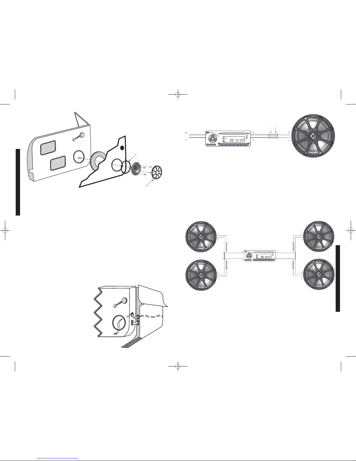
conformément à la figure 2.
S’il n’y a pas de précâblage d’installation audio à l’emplacement voulu, il peut être nécessaire
de faire passer les fils de haut-parleur par le montant de la portière. Éloignez ces fils des
arêtes vives et évitez qu’ils ne risquent
d’être pincés par la portière. L’idéal est de
faire passer les fils de haut-parleur par un
passe-fils de montant de portière existant.
S’il n’y a pas de trou ni passe-fils
accessibles, percez un trou de passage des
fils de haut-parleur dans le montant de
portière. Veillez à ne pas percer d’autres fils
ou les mécanismes des portières. Pour faire
passer un fil électrique dans un trou, insérez
un passe-fils en caoutchouc ou en
plastique afin de protéger le fil,
conformément à la figure 3.
Si les accessoires de fixation fournis ne
conviennent pas pour votre installation, fixez
solidement les haut-parleurs au véhicule
d’une autre façon.
Figure 2
Garniture deportière
Visser l’anneau demontage et le haut-parleurcoaxial dans
la découpedehaut-parleuret fixer la grille.
Portière
Anneau derenfort
(facultatif)
Haut-parleur
coaxial Grille de
haut-parleur
Vis
Disposer les trouspourle câblage et utiliser unpasse-fils
en caoutchouc ou en plastiqueafin deprotéger les fils.
Découpede
haut-parleur
Découpede
haut-parleur
Figure 3
Portière
avant
Panneau avant
Panneau deseuil
deportière
Découpede
haut-parleur
Vers
l’amplificateur
ou l’appareil
source
Anneau de
montage
Remarque: L’anneau de
montage du KS5250se fixeà
l’avant du haut-parleurde
graves. Tousles autres modèles
coaxiaux KSse fixent comme
indiqué à la figure 2.
Raccordement à un seul canal
Le raccordement des fils fournis avec les haut-parleurs Kicker KS est simple. Une extrémité
de chaque fil est pourvue d’un grand connecteur et d’un petit. Le grand connecteur est serti
sur le fil gris et se raccorde à la grande borne (positive) du haut-parleur. Le petit connecteur
est serti sur le fil noir et se raccorde à la petite borne (négative) du haut-parleur. Les autres
extrémités de ces fils se raccordent à l’appareil source ou à l’amplificateur à l’aide des
quatre connecteurs à manchon rouge à sertir fournis. Le fil gris se raccorde à la sortie
positive de l’amplificateur ou de l’appareil source. Le fil noir se raccorde à la sortie négative
de l’amplificateur ou de l’appareil source. Ces raccordements peuvent également être
effectués par soudure en utilisant de la gaine thermo-rétractable et du ruban isolant pour
éviter la mise en court-circuit des haut-parleurs. Voir la figure 4.
Figure 4
Autre canal
Haut-parleurcoaxial KS
raccordé à unseulcanal
Appareil sourceou amplificateur
Remarque : Toutes les caractéristiques techniques et données de fonctionnement sont susceptibles de modifications sans préavis. Pour
obtenir les informations les plus récentes, visitez le site www.kicker.com.
Pour obtenir les meilleures performances des haut-parleurs Kicker, il est conseillé d’utiliser des accessoires et fils Kicker d’origine.
Raccordement de deux haut-parleurs coaxiaux KS à un seul canal
La résistance c.c. des haut-parleurs coaxiaux modernes à hautes performances est
inférieure à ce qui existait auparavant. Les haut-parleurs coaxiaux Kicker KS ont une
résistance de 4 ohms et peuvent fonctionner sur tout appareil source ou amplificateur conçu
pour une charge de 4 ohms. Vous pouvez utiliser deux haut-parleurs coaxiaux KS sur
chaque canal de l’appareil source ou de l’amplificateur en les raccordant en série, comme
indiqué ci-dessus. La qualité sonore est alors améliorée et la distorsion harmonique totale
ainsi que la charge thermique vue par l’appareil source ou l’amplificateur sont réduites. Cela
peut empêcher la mise hors tension de l’amplificateur provoquée par le circuit de protection
contre la surintensité..
Appareil sourceou amplificateur
Haut-parleurs coaxiaux KS
raccordésen série à unseulcanal
Figure 5
Insérer les fils et les sertir à l’aidedes
connecteurs à manchonrouge fournis
pourraccorder les fils du haut-parleurà
ceux del’unité sourceou de
l’amplificateur.
Raccordement
série
KSCOAXIALSPEAKER
INSTALLATION
INSTALLATION
18 19
2008 KS Coax 4in1 a01.qxp 11/29/2007 3:54 PM Page 10

Modèle :
Type de haut-parleur
Diamètre du haut-parleur de graves, pouces (mm)
Diamètre du haut-parleur d’aigus, pouces (mm)
Impédance nominale, ohms
Résistance c.c., ohms
Plage de puissance, watts efficaces
Puissance admissible (watts)
Sensibilité [SPLo], dB pour 1 W à 1 m
Plage de fréquence effective, Hz
Diamètre du trou de montage, pouces (mm)
Profondeur de montage à la surface supérieure, pouces (mm)
Profondeur de montage à la surface inférieure, pouces (mm)
Dépassement du haut-parleur d’aigus, pouces (mm)
Caractéristiques communes à tous les modèles :
Matériau de l’aimant de haut-parleur d’aigus – Néodyme
Matériau du dôme de haut-parleur d’aigus – Kaladex
Type de haut-parleur d’aigus – Dôme équilibré
Matériau du cône de haut-parleur de graves - Polypropylène
Matériau de la bordure de haut-parleur de graves - Santoprene
Si vous avez des questions relatives à l’installation des haut-parleurs coaxiaux Kicker KS, contactez le revendeur agréé Kicker qui vous les a
vendus. Pour obtenir d’autres conseils sur l’installation, cliquez sur l’onglet SUPPORT de la page d’accueil Kicker, www.kicker.com. Sélectionnez
l’onglet d’assistance technique, choisissez le sujet qui vous intéresse, puis téléchargez ou affichez les informations correspondantes. Si vous avez
d’autres questions, écrivez à support@kicker.com ou téléphonez aux services techniques en composant le +1 405-624-8583.
KS400
2 voies
4 (100)
1/2 (13)
4
3
6-30
60
88
60-20k
3 11/16 (94)
1 13/16 (46)
2 1/16 (52)
1/8 (3,2)
KS460
2 voies
4x6 (100x160)
1/2 (13)
4
3
6-30
60
88
50-20k
5 3/4 x 3 1/2 (146x89)
1 13/16(46)
2 (51)
1/16 (1,6)
KS4100
2 voies
4x10 (100x250)
1/2 (13)
4
3
6-35
70
88
45-20k
3 7/8 x 9 5/16 (98x237)
2 7/16 (62)
2 3/4 (70)
0 (0)
KS5250
2 voies
5 1/4 (130)
3/4 (20)
4
3
6-45
135
90
45-21k
4 9/16 (116)
2 (51)
2 1/4 (57)
1/16 (1,6)
KS350
2 voies
3 1/2 (89)
1/2 (13)
4
3
6-20
40
88
80-20k
3 3/16 (81)
1 9/16 (40)
1 7/8 (48)
1/4 (6,4)
Performances
Modèle :
Type de haut-parleur
Diamètre du haut-parleur de graves, pouces (mm)
Diamètre du haut-parleur d’aigus, pouces (mm)
Impédance nominale, ohms
Résistance c.c., ohms
Plage de puissance, watts efficaces
Puissance admissible (watts)
Sensibilité [SPLo], dB pour 1 W à 1 m
Plage de fréquence effective, Hz
Diamètre du trou de montage, pouces (mm)
Profondeur de montage à la surface supérieure, pouces (mm)
Profondeur de montage à la surface inférieure, pouces (mm)
Dépassement du haut-parleur d’aigus, pouces (mm)
Caractéristiques communes à tous les modèles :
Matériau de l’aimant de haut-parleur d’aigus – Néodyme
Matériau du dôme de haut-parleur d’aigus – Kaladex
Type de haut-parleur d’aigus – Dôme équilibré
Matériau du cône de haut-parleur de graves - Polypropylène
Matériau de la bordure de haut-parleur de graves - Santoprene
Si vous avez des questions relatives à l’installation des haut-parleurs coaxiaux Kicker KS, contactez le revendeur agréé Kicker qui vous les a
vendus. Sélectionnez l’onglet d’assistance technique, choisissez le sujet qui vous intéresse, puis téléchargez ou affichez les informations
correspondantes. Si vous avez d’autres questions, écrivez à support@kicker.com ou téléphonez aux services techniques en composant
le +1 405-624-8583.
Performances
KS600
2 voies
6 (160)
3/4 (20)
4
3
6-65
195
90
43-21k
5 (127)
1 15/16 (49)
2 1/4 (57,2)
3/16 (4,8)
KS650
2 voies
6 1/2 (165)
3/4 (20)
4
3
6-65
195
90
40-21k
5 5/8 (143)
2 1/8 (54)
2 3/8 (60)
3/16 (4,8)
KS6930
3 voies
6x9 (150x230)
3/4 (20)
4
3
6-100
300
92
30-21k
6x8 9/16(152x217)
3 3/16 (81)
3 5/8 (92)
5/8 (15,9)
KS680
2 voies
6x8 (150x200)
3/4 (20)
4
3
6-60
180
90
45-21k
5x7 (127x178)
2 3/8 (60)
2 3/4 (70)
0 (0)
KS690
2 voies
6x9 (150x230)
1 (25.4)
4
3
6-90
270
92
30-21k
6x8 9/16(152x217)
3 3/16 (81)
3 5/8 (92)
0 (0)
Conseil pro : Il ne vous manque qu’un caisson de graves Kicker, l’amplificateur
monophonique ZX et quelques câbles pour obtenir un système percutant !
La gamme d’amplificateurs monophoniques Kicker ZX permet de tirer des graves
robustes d’un appareil source existant ou standard. Demandez à votre revendeur
de vous conseiller sur les caissons de graves Kicker Comp et CompVR.
KSCOAXIALSPEAKER
20 21
PERFORMANCE
PERFORMANCE
2008 KS Coax 4in1 a01.qxp 11/29/2007 3:54 PM Page 11

KSCOAXIALSPEAKER 11292007-a+08KS
P.O. Box 459 • Stillwater, Oklahoma 74076 • U.S.A. • (405) 624-8510
AcousticsLimitedWarranty
Kicker warrants this product to be free from defects in material and workmanship under normal use for a period of
THREE (3) MONTHS from date of original purchase with receipt. When purchased from an Authorized KICKER Dealer
it is warranted for ONE (1) YEAR from date of original purchase with receipt. In all cases you must have the original
receipt. Should service be necessary under this warranty for any reason due to manufacturing defect or malfunction
during the warranty period, Kicker will repair or replace (at its discretion) the defective merchandise with equivalent
merchandise at no charge. Warranty replacements may have cosmetic scratches and blemishes. Discontinued
products may be replaced with more current equivalent products.
This warranty is valid only for the original purchaser and is not extended to owners of the product subsequent to the
original purchaser. Any applicable implied warranties are limited in duration to a period of the express warranty as
provided herein beginning with the date of the original purchase at retail, and no warranties, whether express or
implied, shall apply to this product thereafter. Some states do not allow limitations on implied warranties; therefore
these exclusions may not apply to you. This warranty gives you specific legal rights; however you may have other
rights that vary from state to state.
WHAT TO DO IF YOU NEEDWARRANTY OR SERVICE
Defective merchandise should be returned to your local Authorized Stillwater Designs (Kicker) Dealer for warranty
service. Assistance in locating an Authorized Dealer can be found at www.kicker.com or by contacting Stillwater
Designs directly. You can confirm that a dealer is authorized by asking to see a current authorized dealer window
decal.
If it becomes necessary for you to return defective merchandise directly to Stillwater Designs (Kicker), call the Kicker
Customer Service Department at (405) 624-8510 for a Return Merchandise Authorization (RMA) number. Package all
defective items in the original container or in a package that will prevent shipping damage, and return to:
Stillwater Designs, 5021 North Perkins Road, Stillwater, OK 74075
The RMA number must be clearly marked on the outside of the package. Please return only defective components.
The return of functioning items increases your return freight charges. Non-defective items will be returned freight-
collect to you.
Include a copy of the original receipt with the purchase date clearly visible, and a "proof-of-purchase" statement listing
the Customer's name, Dealer's name and invoice number, and product purchased. Warranty expiration on items
without proof-of-purchase will be determined from the type of sale and manufacturing date code. Freight must be
prepaid; items sent freight-collect, or COD, will be refused.
WHAT ISNOT COVERED?
This warranty is valid only if the product is used for the purpose for which it was designed.
It does not cover:
o Damage due to improper installation
o Subsequent damage to other components
o Damage caused by exposure to moisture, excessive heat, chemical cleaners, and/or UV radiation
o Damage through negligence, misuse, accident or abuse. Repeated returns for the same damage may be
considered abuse
o Any cost or expense related to the removal or reinstallation of product
o Speakers damaged due to amplifier clipping or distortion
o Items previously repaired or modified by any unauthorized repair facility
o Return shipping on non-defective items
o Products with tampered or missing barcode labels
o Products returned without a Return Merchandise Authorization (RMA) number
o Freight Damage
o The cost of shipping product to Kicker
o Service performed by anyone other than Kicker
HOW LONG WILL IT TAKE?
Kicker strives to maintain a goal of 24-hour service for all acoustics (subwoofers, midrange and coaxial drivers,
tweeters, crossovers, etc) returns. Delays may be incurred if lack of replacement inventory or parts is encountered.
Failure to follow these steps may void your warranty. Any questions can be directed to the Kicker Customer Service
Department at (405) 624-8510.
InternationalWarranty
Contact your International Kicker dealer or distributor concerning specific procedures for your country's warranty
policies.
WARNING: KICKER products are capable of producing sound levels that can permanently damage your hearing!
Turning up a system to a level that has audible distortion is more damaging to your ears than listening to an
undistorted system at the same volume level. The threshold of pain is always an indicator that the sound level is too
loud and may permanently damage your hearing. Please use common sense when controlling volume.
GARANTÍA INTERNACIONAL VersiónEspañol
Comuníquese con su concesionario o distribuidor Kicker internacional para obtener infor ación sobre procedimientos
específicos relacionados con las normas de garantía de su país.
ADVERTENCIA: Los excitadores Kicker son capaces de producir niveles de sonido que pueden dañar
permanentemente el oído. Subir el volumen del sistema hasta un nivel que produzca distorsión es más dañino para el
oído que escuchar un sistema sin distorsión al mismo volumen. El dolor es siempre una indicación de que el sonido es
muy fuerte y que puede dañar permanentemente el oído. Sea precavido cuando controle el volumen.
La frase "combustible para vivir la vida Livin' Loud™ a todo volumen" se refiere al entusiasmo por la vida que la marca
Kicker de estéreos de automóvil representa y a la recomendación a nuestros clientes de que vivan lo mejor posible ("a
todo volumen") en todo sentido. La línea de altavoces y amplificadores Kicker es la mejor del mercado de audio de
automóviles y por lo tanto representa el "combustible" para vivir a todo volumen en el área de "estéreos de automóvil"
de la vida de nuestros clientes. Recomendamos a todos nuestros clientes que obedezcan todas las reglas y
reglamentos locales sobre ruido en cuanto a los niveles legales y apropiados de audición fuera del vehículo.
INTERNATIONALE GARANTIE DeutscheVersion
Nehmen Sie mit Ihren internationalen Kicker-Fachhändler oder Vertrieb Kontakt auf, um Details über die
Garantieleistungen in Ihrem Land zu erfahren.
WARNUNG: KICKER-Treiber können einen Schallpegel erzeugen, der zu permanenten Gehörschäden führen kann!
Wenn Sie ein System auf einen Pegel stellen, der hörbare Verzerrungen erzeugt, schadet das Ihren Ohren mehr, als ein
nicht verzerrtes System auf dem gleichen Lautstärkepegel. Die Schmerzschwelle ist immer eine Anzeige dafür, dass
der Schallpegel zu laut ist und zu permanenten Gehörschäden führen kann. Seien Sie bei der Lautstärkeeinstellung
bitte vernünftig!
Der Slogan "Treibstoff für Livin' Loud" bezieht sich auf die mit den Kicker-Autostereosystemen assoziierte
Lebensfreude und die Tatsache, dass wir unsere Kunden ermutigen, in allen Aspekten ihres Lebens nach dem Besten
("Livin' Loud") zu streben. Die Lautsprecher und Verstärker von Kicker sind auf dem Markt für Auto-Soundsysteme
führend und stellen somit den "Treibstoff" für das Autostereoerlebnis unserer Kunden dar. Wir empfehlen allen unseren
Kunden, sich bezüglich der zugelassenen und passenden Lautstärkepegel außerhalb des Autos an die örtlichen
Lärmvorschriften zu halten.
GARANTIE INTERNATIONALE VersionFrançaise
Pour connaître les procédures propres à la politique de garantie de votre pays, contactez votre revendeur ou
distributeur International Kicker.
AVERTISSEMENT: Les haut-parleurs Kicker ont la capacité de produire des niveaux sonores pouvant endommager
l'ouïe de façon irréversible ! L'augmentation du volume d'un système jusqu'à un niveau présentant une distorsion
audible endommage davantage l'ouïe que l'écoute d'un système sans distorsion au même volume. Le seuil de la
douleur est toujours le signe que le niveau sonore est trop élevé et risque d'endommager l'ouïe de façon irréversible.
Réglez le volume en faisant prevue de bon sens !
L'expression " carburant pour vivre plein pot " fait référence au dynamisme de la marque Kicker d'équipements audio
pour véhicules et a pour but d'encourager nos clients à faire le maximum (" vivre plein pot ") dans tous les aspects de
leur vie. Les haut-parleurs et amplificateurs Kicker sont les meilleurs dans le domaine des équipements audio et
représentent donc pour nos client le " carburant pour vivre plein pot " dans l'aspect " installation audio de véhicule "
de leur vie. Nous encourageons tous nos clients à respecter toutes les lois et réglementations locales relatives aux
niveaux sonores acceptables à l'extérieur des véhicules.
GARANTIE
WARRANTY
22 23
2008 KS Coax 4in1 a01.qxp 11/29/2007 3:54 PM Page 12
This manual suits for next models
9
Table of contents
Languages:
Other Kicker Car Speakers manuals

Kicker
Kicker Solo X S12X User manual

Kicker
Kicker DS35 User manual

Kicker
Kicker KS35 User manual

Kicker
Kicker DS7130 User manual

Kicker
Kicker KSTweeters KS13 User manual

Kicker
Kicker RMB6 User manual

Kicker
Kicker KS6930 User manual

Kicker
Kicker KSTweeters KS13 User manual

Kicker
Kicker PS692 User manual

Kicker
Kicker RS56.2 User manual

Kicker
Kicker KS5.2 User manual

Kicker
Kicker KSTweeters KS25 User manual

Kicker
Kicker KMFC65 User manual

Kicker
Kicker KST20 User manual

Kicker
Kicker KMT60 User manual

Kicker
Kicker KS5.2 User manual

Kicker
Kicker KS6930 User manual

Kicker
Kicker SS56.2 User manual

Kicker
Kicker KSC35 User manual

Kicker
Kicker KS Series User manual