Kicker QSS674 User manual

QSS COMPONENT SYSTEM
Owner’s Manual | English
Manual del Propietario | Español
SISTEMA DE ALTAVOCES COMPONENTES QSS
Benutzerhandbuch | Deutsch
QSS-KOMPONENTENSYSTEM
Manuel d’utilisation | Française
SYSTÈME À COMPOSANTS QSS
QSS COMPONENT SYSTEM
QSS65 | QSS67
2014 QSS Multilingual Rev C.indd 12014 QSS Multilingual Rev C.indd 1 9/24/2013 2:31:40 PM9/24/2013 2:31:40 PM

2
QSS COMPONENT SYSTEM
Owner’s Manual
The KICKER QSS-series component systems offer unmatched audio fidelity for vehicle applications. Whether you’re
configuring the ultimate multi-speaker and subwoofer surround system or simply upgrading from dull, lifeless factory
speakers, the QSS component systems deliver the most pleasing full-range sound on the market today! Key features of
our highest-end component systems include:
Authorized KICKER Dealer:
Purchase Date:
Speaker Serial Number:
Model QSS65 QSS67
Woofer [in, mm] 6-1/2, 160 6-3/4, 165
Tweeter [in,mm] 1-3/16, 30 1-3/16, 30
Dome Material Tetoron® Tetoron®
Rated Impedance [Ω] 4 4
Peak Power Handling [ Watts] 180 200
Continuous Power Handling [Watts RMS] 90 100
Sensitivity [1W, 1m] 86dB 87dB
Frequency Response [Hz] 50–22k 40–22k
Woofer Mounting Hole Diameter [in, mm] 5-1/16, 129 5-7/16, 138
Woofer Bottom Mount Depth [in, mm] 2.5, 63.5 2.5, 63.5
Flush Mount Tweeter Hole Diameter [in,mm] 1-13/16, 46 1-13/16, 46
Flush Mount Tweeter Depth [in,mm] 1-1/8, 29 1-1/8, 29
High Pass [dB], at Frequency [Hz] 24, 2800 24, 2800
Low Pass [dB], at Frequency [Hz] 12, 2800 12, 2800
High Frequency Output Attenuation [dB] 0, +3, +6 0, +3, +6
MODELS: QSS65 / QSS67
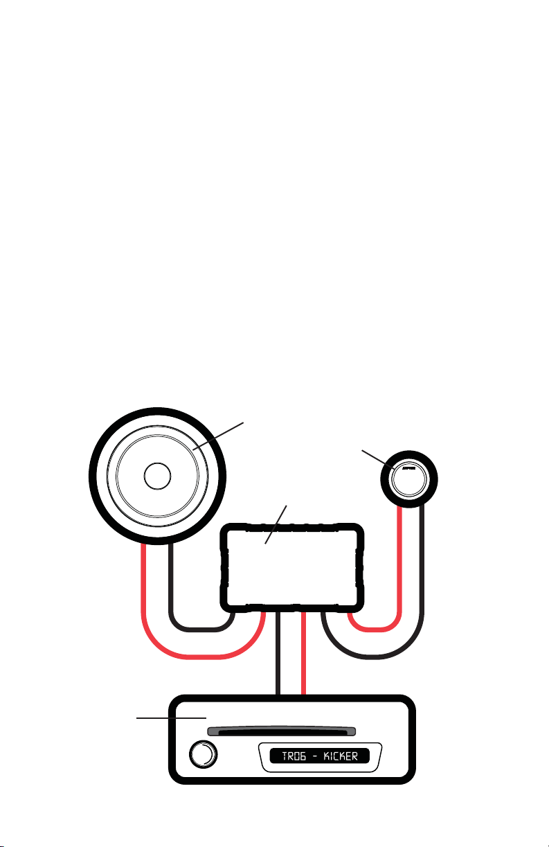
Crossover Woofer Tweeter
Zobel Impedance correction to flatten
impedance network
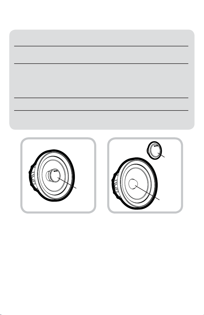
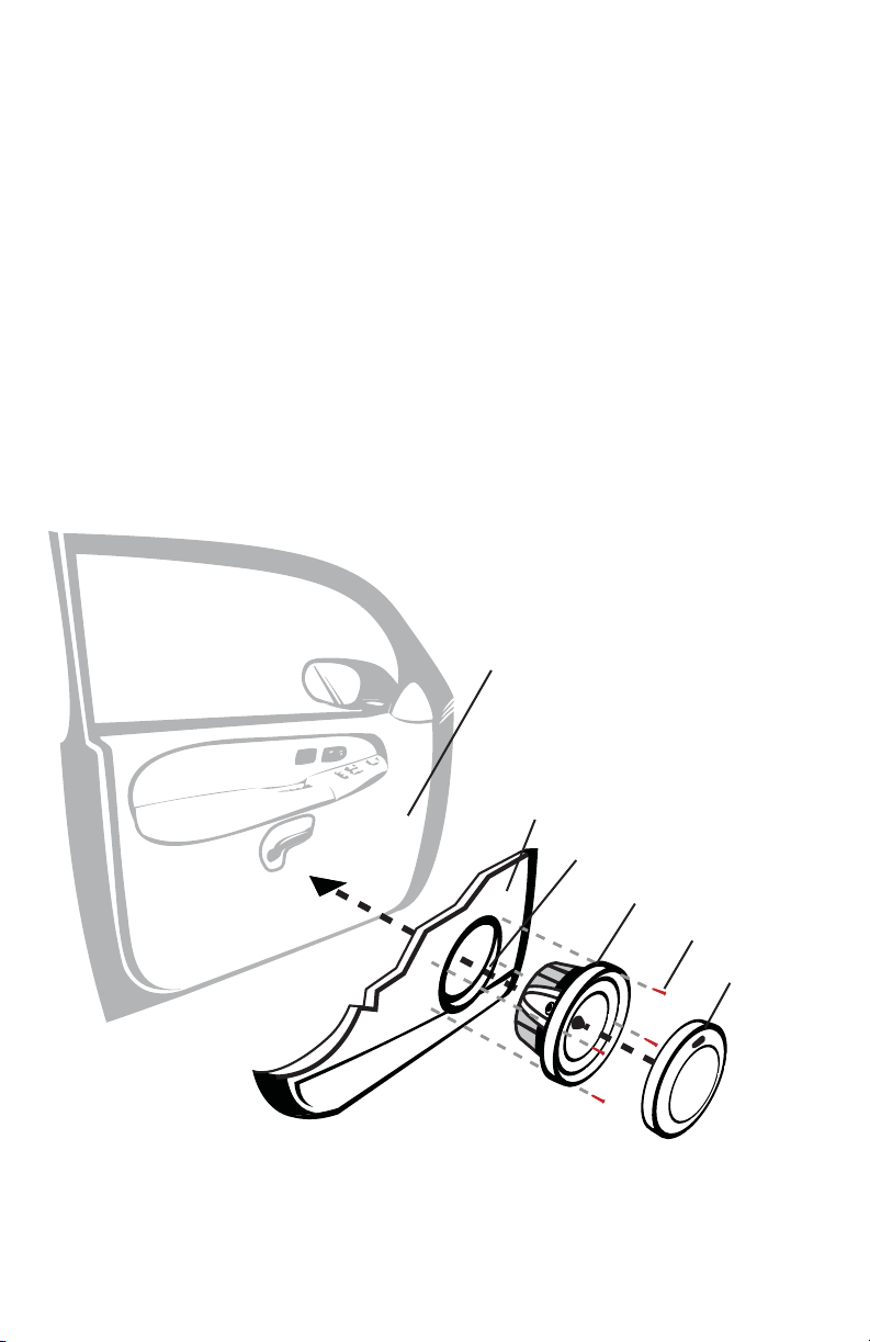
Revolutionary surround design maximizes
cone area, maintains standard cutout size
Pressed polyfil inserted behind the
dome for acoustic dampening
Mylar capacitors and audiophile-grade air core
inductors
Copper shorting ring on the pole piece to
reduce distortion
Dual Neodymium magnets with
tuning vent
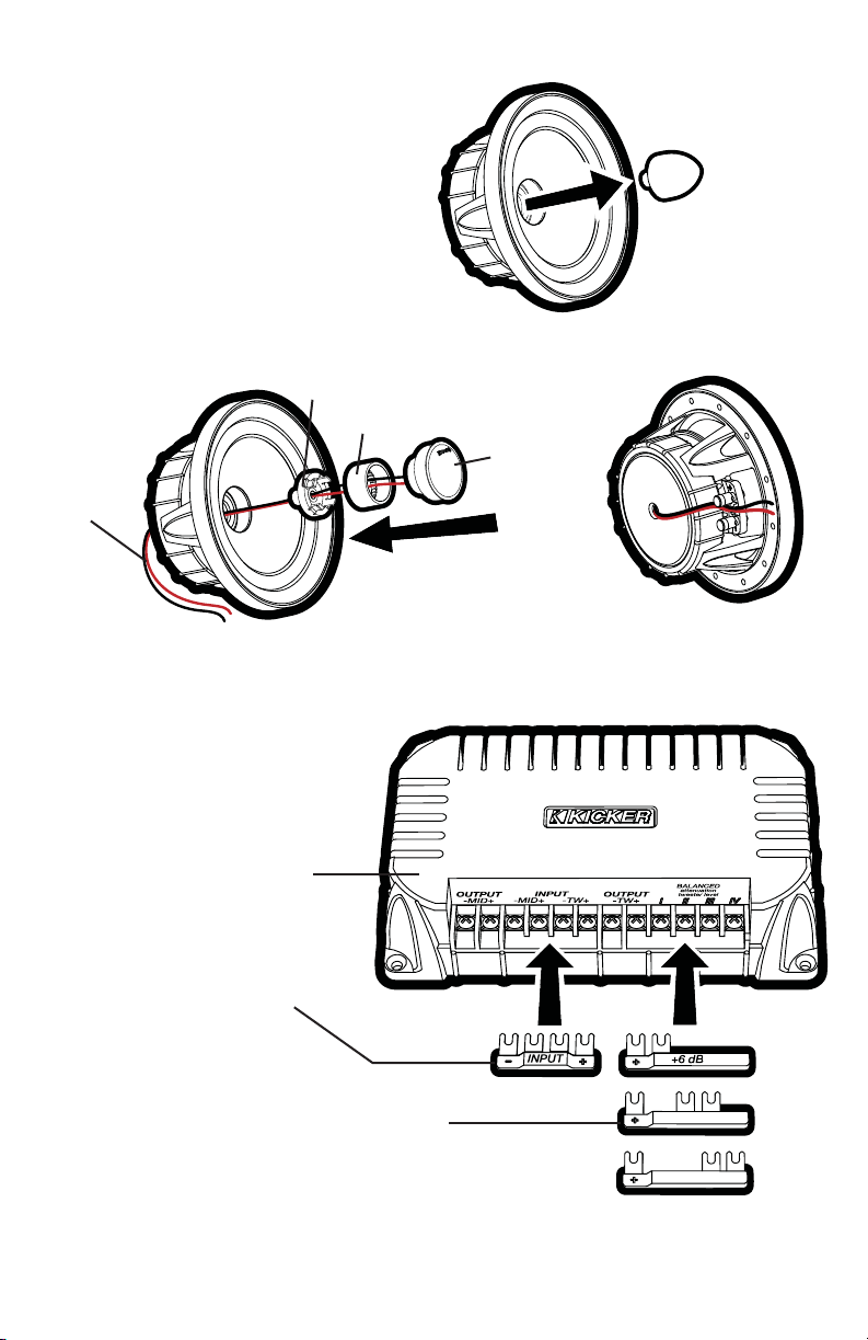
Bi-amplification capable Polished back plate Dupont Tetoron composite dome
Asymmetrical circuit design Tri-tech cone design Open wire mesh-grill
Brushed aluminum base heat sink Aluminum phase plug Sealed and tuned chamber
Balanced tweeter attenuation Copper-clad aluminum coil wire Copper-clad aluminum coil wire
Heatsinked resistors for increased power-
handling
Ultra-durable Spiral Tinsel leads, woven
through the duo-wave spider
Acoustic cavity coupled to magnet
reduces internal reflections
Dedicated attenuation jumpers (0, +3 or +6
dB) for a clean connection with less resistance
Strongest available cast aluminum basket,
increasing magnetism
Enclosure volume allows for
lower frequencies, better off-axis
response
Illuminated tweeter protection Nickel-plated, spring-loaded terminals Extended Tweeter post
PERFORMANCE
2014 QSS Multilingual Rev C.indd 22014 QSS Multilingual Rev C.indd 2 9/24/2013 2:31:57 PM9/24/2013 2:31:57 PM

3
CONFIGURATION
Before mounting and wiring the QSS component system, determine which configuration you will use for
the speakers and crossover.
QSS Speaker
Configurations ADVANTAGES CONSIDERATIONS
Coaxial great for space-limited applications
or when separate tweeter mounting
is not possible
high frequencies may not be as
prominent | tweeter output may
need to be increased at crossover
Separates optimal sound quality and improved
sonic imaging (with proper tweeter
mounting)
trickier install | vehicle must have a
good tweeter mounting location
QSS Crossover
Configurations ADVANTAGES CONSIDERATIONS
Conventional 2-way easy install | ideal when available
amplifier channels are limited
audio fidelity not quite as high as
bi-amplified configuration
Bi-amplified optimal sound quality; more efficient
usage of amplifier power
requires at least 4 amplifier
channels | slightly trickier install
SPEAKER CONFIGURATION
The QSS component system comes packaged in a separates configuration.
To use a coaxial configuration, see Fig. 1 and follow these steps:
1. Unscrew and remove the aluminum phase plug from the center of the woofer.
2. Screw the coaxial mounting adapter into the woofer in place of the phase plug.
3. Screw the tweeter into the tweeter post.
4. Thread the tweeter’s lead wires through the center of the woofer.
5. Snap the tweeter post onto the coaxial mounting adapter.
6. Rotate the tweeter clockwise for the most appealing position.
7. Secure the tweeter’s lead wires using the clip on the underside of the woofer.
Coaxial Configuration Separates Configuration
tweeter
tweeter
phase plug
2014 QSS Multilingual Rev C.indd 32014 QSS Multilingual Rev C.indd 3 9/24/2013 2:31:58 PM9/24/2013 2:31:58 PM

4
Step 1
Steps 2–6 Step 7
tweeter
tweeter post
coaxial mounting adapter
tweeter lead
wires
QSS crossover
0 dB
+3 dB
INPUT jumper.
Install only for 2-way configurations;
do not install if bi-amping.
tweeter output-level jumpers.
One of these jumpers MUST be installed. Higher
numbers mean more volume from the tweeter.
Fig. 2
Fig. 1
Configuring the QSS for
Coaxial Operation
2014 QSS Multilingual Rev C.indd 42014 QSS Multilingual Rev C.indd 4 9/24/2013 2:31:58 PM9/24/2013 2:31:58 PM

5
WIRING
We recommend using 16 gauge (or larger) wire. The QSS components are rated at 4 ohms and work
with any source unit or amplifier designed to operate at a 4 ohm load. Make sure your source unit or
amplifier is rated for 4 ohm operation.
Crossover in 2-way configuration | One component set per channel
• At least two amplifier channels are needed for stereo operation (only one channel is shown)
- IN +
OUT
-MID+
OUT
-TW+
-OUT+
+-
+-
tweeter
crossover
woofer
source unit / amplifier
CROSSOVER CONFIGURATION
The KICKER QSS crossover can be configured as a conventional 2-way crossover by installing the
included INPUT jumper into the - MID + -TW + input terminals as shown in Fig. 2. In this configuration,
the amplified signal from your source unit or amplifier should be wired to the + and - terminals indicated on
the INPUT jumper.
The QSS crossover can also be configured for bi-amp wiring by removing (or simply not installing)
the INPUT jumper. To use the bi-amp configuration, you must connect two amplified signals to each
crossover (you will need at least four amplifier channels). Install one of the included tweeter output-
level jumpers (0 dB, +3 dB, or +6 dB) to adjust the tweeter output level. Installing jumpers with higher
numbers will result in more volume from the tweeter.
2014 QSS Multilingual Rev C.indd 52014 QSS Multilingual Rev C.indd 5 9/24/2013 2:31:58 PM9/24/2013 2:31:58 PM

6
+
-
+
-
IN
-MID+
IN
-TW+
-OUT
+MID
OUT +
TW -
-MID+
CH2
LEFT OUTPUT
-TW+
CH1
Crossover in bi-amp configuration Two channels per component set
• At least four amplifier channels are needed for stereo operation (only two channels are shown)
amplifier / source unit
(must have at least four channels)
Pro Tip: Looking for the next step in audio performance from your QSS components? Upgrade to a
KICKER IQ or KX 4 or 5-channel amplifier for each QSS component system you have installed to take
full advantage of the QSS’s bi-amping capabilities. With a dedicated amplifier channel for each tweeter
and each midrange driver, you’ll have a more efficient system that will deliver a clearer soundstage and
an increasingly dramatic dynamic response. In other words, your music will be more expansive and
captivating.
2014 QSS Multilingual Rev C.indd 62014 QSS Multilingual Rev C.indd 6 9/24/2013 2:31:58 PM9/24/2013 2:31:58 PM

7
WOOFER MOUNTING
The KICKER QSS components are designed for free-air applications and do not require a sealed
enclosure for optimum performance. It is important to isolate the sound coming from the front of the
speaker from the sound radiating from the back of the speaker. This is most easily accomplished by
mounting the speakers in a vehicle’s factory locations or in a location with a semi-isolated rear chamber
(like the rear deck of a car behind the rear seats).
If you are replacing factory speakers in their original locations, you may have to enlarge the speaker
cut-outs and pre-drill new screw holes using a 7/64” (2.5mm) bit. Custom mounting locations will require
more preparation and work. Make sure that the speaker will not interfere with trunk and door opening and
closing mechanisms and that the enclosed screws will not puncture the fuel tank, puncture wiring, or
interfere with any other mechanical parts on the underside of the mounting surface. Cycle the windows all
the way down and up.
If the speaker cut-out locations require you to cut metal, avoid structural metal and braces. Mount the
speaker to the vehicle as outlined in Fig. 3.
door body
door panel
speaker cut-out
QSS woofer
speaker grille
screws
Fig. 3
2014 QSS Multilingual Rev C.indd 72014 QSS Multilingual Rev C.indd 7 9/24/2013 2:31:59 PM9/24/2013 2:31:59 PM

8
Fig. 4
Flush Mounting the Tweeter
TWEETER MOUNTING
The tweeter can be mounted one of three ways: flush, angled, and coaxial mounting. For flush mounting
applications, see Fig. 4. Choose a flat location on the panel with space behind the panel to allow room
for the mounting nut, motor structure, and tweeter post. After checking the clearances, cut a 1-13/16”
(46mm) diameter mounting hole in the panel. Position the mounting nut behind the panel. Feed the
wire through the optional flush ring, the hole in the panel, and the mounting nut. Mount the tweeter by
screwing the mounting nut onto the tweeter.
For angled mounting applications choose a flat location on the panel with space behind the panel to
allow room for the mounting nut, motor structure, tweeter post, and back angle ring. After checking the
clearances, cut a 1-13/16” (46mm) diameter mounting hole in the panel. Place the front angle ring in front
of the panel. Then place the wire and tweeter through the front angle ring and into the panel. Next, place
the wire through the back angle ring, place the back angle ring over the rear of the tweeter, and line-up
the narrow part of the front angle ring for the preferred angle of operation. Place the wire through the
mounting nut and loosely tighten the mounting nut around the tweeter. Rotate all the parts in unison until
the tweeter is angled in the desired direction. Secure the assembly by tightening the mounting nut. See
Fig. 5.
mounting nut
Trim the mounting nut legs at the score
lines to accommodate thicker panels.
mounting nut
back angle ring
Fig. 5
Angle Mounting the Tweeter
front angle ring
rounded surface
inset surface
panel
panel
flush ring
tweeter
tweeter
2014 QSS Multilingual Rev C.indd 82014 QSS Multilingual Rev C.indd 8 9/24/2013 2:31:59 PM9/24/2013 2:31:59 PM

9
CROSSOVER MOUNTING
Mount the crossover in a location that is easy to access for wiring and tweeter output level adjustment.
Make sure that the crossover will not be exposed to water. The bottom of the car door is not a good
location. If you must mount the crossover in the car door, exercise caution as water can accumulate in the
bottom of the door. Keep the crossover high in the door and shielded from water.
door jamb
QSS crossover.
(mounted inside
door panel)
rubber
grommets
from amplifier or
source unit
woofer mounting hole
tweeter mounting hole
to woofer
terminals
to tweeter
lead wires
The speaker wire should be kept away from sharp edges and avoid the possibility of getting pinched by
the door. An existing grommet in the door jamb is the ideal place to run the speaker wire. If the factory
hole and grommet do not exist or are inaccessible, you must drill a hole to run the speaker wire through
the door jamb. Be careful not to drill into other wiring or existing door mechanisms. Any time a wire is run
through a hole, it is necessary to insert a rubber or plastic grommet to protect the wire from damage.
2014 QSS Multilingual Rev C.indd 92014 QSS Multilingual Rev C.indd 9 9/24/2013 2:31:59 PM9/24/2013 2:31:59 PM

10
Note: All specifications and performance figures are subject to change. Please visit www.kicker.com for the
most current information. To get the best performance from your new KICKER speakers, we recommend using
genuine KICKER accessories and wiring. Please allow two weeks of break-in time for the speakers to reach optimum
performance.
Snap-on grille or trim-ring if desired
Rotate grille/trim-ring counter-
clockwise to remove
GRILLE MOUNTING
2014 QSS Multilingual Rev C.indd 102014 QSS Multilingual Rev C.indd 10 9/24/2013 2:31:59 PM9/24/2013 2:31:59 PM

11
ACOUSTICS LIMITED WARRANTY
When purchased from an Authorized KICKER Dealer, KICKER warrants this product to be free from defects in material
and workmanship under normal use for a period of ONE (1) YEAR from date of original purchase. If this product is
identified as “Refurbished” or “B Goods”, the warranty is limited to a period of THREE (3) MONTHS from date of original
purchase. In all cases you must have the original receipt. Should service be necessary under this warranty for any reason
due to manufacturing defect or malfunction during the warranty period, KICKER will repair or replace (at its discretion)
the defective merchandise with equivalent merchandise. Warranty replacements may have cosmetic scratches and
blemishes. Discontinued products may be replaced with more current equivalent products. This warranty is valid only for
the original purchaser and is not extended to owners of the product subsequent to the original purchaser. Any applicable
implied warranties are limited in duration to a period of the express warranty as provided herein beginning with the date of
the original purchase at retail, and no warranties, whether express or implied, shall apply to this product thereafter. Some
states do not allow limitations on implied warranties; therefore, these exclusions may not apply to you. This warranty
gives you specific legal rights; however you may have other rights that vary from state to state.
WHAT TO DO IF YOU NEED WARRANTY OR SERVICE:
Defective merchandise should be returned to your local Authorized Stillwater Designs (KICKER) Dealer for warranty
service. Assistance in locating an Authorized Dealer can be found at www.kicker.com or by contacting Stillwater Designs
directly. You can confirm that a dealer is authorized by asking to see a current authorized dealer window decal.
If it becomes necessary for you to return defective merchandise directly to Stillwater Designs (KICKER), call the KICKER
Customer Service Department at (405) 624-8510 for a Return Merchandise Authorization (RMA) number. Package only
the defective items in a package that will prevent shipping damage, and return to:
Stillwater Designs, 3100 North Husband St, Stillwater, OK 74075
The RMA number must be clearly marked on the outside of the package. Please return only defective component
systems. The return of functioning items increases your return freight charges. Non-defective items will be returned
freightcollect to you. For example, if a subwoofer is defective, only return the defective subwoofer, not the entire
enclosure. Include a copy of the original receipt with the purchase date clearly visible, and a “proof-of-purchase”
statement listing the Customer’s name, Dealer’s name and invoice number, and product purchased. Warranty expiration
on items without proof-of-purchase will be determined from the type of sale and manufacturing date code. Freight must
be prepaid; items sent freight-collect, or COD, will be refused.
WHAT IS NOT COVERED?
This warranty is valid only if the product is used for the purpose for which it was designed. It does not cover:
o Damage due to improper installation
o Subsequent damage to other components
o Damage caused by exposure to moisture, excessive heat, chemical cleaners, and/or UV radiation
o Damage through negligence, misuse, accident or abuse. Repeated returns for the same damage may be
considered abuse
o Any cost or expense related to the removal or reinstallation of product
o Speakers damaged due to amplifier clipping or distortion
o Items previously repaired or modified by any unauthorized repair facility
o Return shipping on non-defective items
o Products with tampered or missing barcode labels
o Products with tampered or missing serial numbers
o Products returned without a Return Merchandise Authorization (RMA) number
o Products purchased from an UNAUTHORIZED dealer
o Freight Damage
o The cost of shipping product to KICKER
o Service performed by anyone other than KICKER
HOW LONG WILL IT TAKE?
KICKER strives to maintain a goal of one-week service for all acoustics (subwoofers, midrange drivers, tweeters,
crossovers, etc) returns. Delays may be incurred if lack of replacement inventory or parts is encountered. Failure to
follow these steps may void your warranty. Any questions can be directed to the KICKER Customer Service Department
at (405) 624-8510. Contact your International KICKER dealer or distributor concerning specific procedures for your
country’s warranty policies.
P.O. Box 459 • Stillwater, Oklahoma 74076 • USA • (405) 624–8510
stillwaterdesigns
2014 QSS Multilingual Rev C.indd 112014 QSS Multilingual Rev C.indd 11 9/24/2013 2:31:59 PM9/24/2013 2:31:59 PM

12
Manual del propietario del
SISTEMA DE COMPONENTES QSS
Los sistemas de componentes de la serie QSS de KICKER ofrecen una fidelidad de audio inigualable para aplicaciones para vehículos.
Ya sea para configurar el último sistema de sonido envolvente con altavoces múltiples y subwoofer o simplemente para mejorar la versión
de parlantes aburridos y sin vida de fábrica, los sistemas de componentes QSS brindan el sonido de gama completa más placentero del
mercado en la actualidad!
Distribuidor autorizado de KICKER:
Fecha de compra
Número de modelo del altavoz:
Modelo QSS65 QSS67
Altavoz [pulg., mm.] 6-1/2, 160 6-3/4, 165
Altavoz de agudos [pulg.,mm.] 1-3/16, 30 1-3/16, 30
Material de la cúpula Tetoron® Tetoron®
Impedancia nominal [Ω] 4 4
Potencia máxima [ Vatios] 180 200
Potencia continua [RMS Vatios] 90 100
Sensibilidad [1W, 1m] 86dB 87dB
Respuesta de frecuencia [Hz]
50–22k 40–22k
Diámetro del orificio de montaje del altavoz [pulg., mm.] 5-1/16, 129 5-7/16, 138
Profundidad del montaje inferior del altavoz [pulg., mm.] 2.5, 63.5 2.5, 63.5
Diámetro del orificio de montaje para empotrado del altavoz de agudos [pulg.,mm.]
1-13/16, 46 1-13/16, 46
Profundidad de montaje para empotrado del altavoz de agudos [pulg.,mm.] 1-1/8, 29 1-1/8, 29
Paso alto [dB], en frecuencia [Hz] 24, 2800 24, 2800
Paso bajo [dB], en frecuencia [Hz] 12, 2800 12, 2800
Atenuación de salida de alta frecuencia [dB] 0, +3, +6 0, +3, +6
MODELO: QSS65 / QSS67
Divisor de frecuencias Altavoz de graves Altavoz de agudos
Red de corrección de impedancia Zobel para equilibrar
la red de impedancia
Su diseño envolvente revolucionario maximiza
el área de cobertura y mantiene el tamaño del
interruptor
Relleno de poliéster prensado colocado
detrás de la cúpula para obtener
atenuación acústica
Capacitores Mylar e inductores con núcleo de aire con
calidad de audio profesional
Anillo de cortocircuito de cobre en el polo para
reducir la distorsión
Imanes duales de neodimio con
conducto de afinación
Con capacidad de biamplificación Placa posterior pulida Cúpula compuesta de Tetoron Dupont
Diseño de circuito asimétrico Diseño cónico Tri-tech Rejilla metálica de circuito abierto
Disipador térmico de aluminio pulido Corrector de fase de aluminio Cámara afinada y sellada
Atenuación balanceada del altavoz de agudos Cable de bobina de aluminio enchapado en cobre Cable de bobina de aluminio enchapado
en cobre
Resistores con disipación térmica para una mayor
potencia
Trencillas en espiral ultra duraderas, tejidas a
través del núcleo bidireccional
La cavidad acústica con imán reduce las
reflexiones internas
Puentes atenuantes especializados (0, +3 ó +6 dB)
para una conexión limpia con menos resistencia
La canasta de aluminio fundido más fuerte
disponible, que aumenta el magnetismo
El volumen envolvente permite
frecuencias más bajas, mejor respuesta
de frecuencia fuera de eje
Protección iluminada del altavoz de agudos Terminales accionadas por resortes y niqueladas Poste de altavoz de agudos extendido
RENDIMIENTO
2014 QSS Multilingual Rev C.indd 122014 QSS Multilingual Rev C.indd 12 9/24/2013 2:31:59 PM9/24/2013 2:31:59 PM

13
Configuración coaxial Configuración por separado
tweeter
tweeter
corrector
de fase
CONFIGURACIÓN
Antes de montar y realizar el cableado del sistema de componentes QS, determine qué configuración
utilizará para los altavoces y el crossover.
Configuraciones de
los altavoces QS
VENTAJAS CONSIDERACIONES
Coaxial
Excelente para aplicaciones con
espacio limitado o cuando no es posible
el montaje del tweeter por separado
Es posible que las frecuencias altas
no sean tan prominentes | Es posible
que se necesite aumentar la salida
del tweeter en el crossover
Por separado Óptima calidad de sonido y mejor
imagen acústica (con el montaje
adecuado del tweeter)
Instalación más difícil | El vehículo
debe tener una buena ubicación
de montaje del tweeter
Configuraciones
del crossover QS VENTAJAS CONSIDERACIONES
Convencional de
2 vías
Fácil de instalar/Ideal cuando los canales
para amplificadores son limitados
Fidelidad de audio no tan buena como
en la configuración biamplificada
Biamplificada Óptima calidad de sonido;
uso más eficiente de la potencia
del amplificador
Requiere al menos 4 canales para
amplificadores | Instalación un
poco más difícil
CONFIGURACIÓN DE LOS ALTAVOCES
El sistema de componentes QSS viene empaquetado en una configuración por separado.
Para utilizar una configuración coaxial, vea la Fig. 1 y siga los pasos a continuación:
1. Desatornille y retire el corrector de fase de aluminio del centro del woofer.
2. Atornille el adaptador de montaje coaxial en el woofer en el lugar del corrector de fase.
3. Atornille el tweeter a la base del tweeter.
4. Pase los cables conductores del tweeter por el centro del woofer.
5. Enganche el tweeter en la base de montaje coaxial.
6. Rote el tweeter para lograr la posición más llamativa.
7. Asegure los cables de alimentación del tweeter con la pinza en la parte inferior del woofer.
2014 QSS Multilingual Rev C.indd 132014 QSS Multilingual Rev C.indd 13 9/24/2013 2:31:59 PM9/24/2013 2:31:59 PM

14
0 dB
+3 dB
Paso 1
Pasos 2 a 6 Paso 7
tweeter
base del tweeter
adaptador de montaje coaxial
cables de
alimentación
del tweeter
crossover QS
puente INPUT (entrada)
Instalar sólo para configuraciones
de 2 vías; No instalar si es
biamplificada.
puentes de nivel de salida del tweeter.
Se DEBE instalar uno de estos puentes. Si se usan
números más altos, el tweeter produce más volumen.
Fig. 2
Fig. 1
Configuración de QSS para
el funcionamiento coaxial
2014 QSS Multilingual Rev C.indd 142014 QSS Multilingual Rev C.indd 14 9/24/2013 2:32:00 PM9/24/2013 2:32:00 PM

15
- IN +
OUT
-MID+
OUT
-TW+
-OUT+
+-
+-
CONFIGURACIÓN DEL CROSSOVER
El crossover QSS de KICKER se puede configurar como un crossover convencional de 2 vías si se instala el
puente INPUT (entrada) en las terminales de entrada - MID + - TW + como se muestra en la Fig. 2.
En esta configuración, la señal amplificada de su unidad fuente o amplificador se deben conectar a las
terminales + y - que se indican en el puente INPUT (entrada).
El crossover QSS también se puede configurar para un cableado con dos amplificadores si se saca
(o simplemente no se instala) el puente INPUT (entrada). Para utilizar la configuración de dos
amplificadores, debe conectar dos señales amplificadas a cada crossover (necesitará al menos cuatro
canales para amplificadores). Instale uno de los puentes de nivel de salida del tweeter (0 dB, +3 dB
o +6 dB) incluidos para ajustar el nivel de salida del tweeter. Si se instalan los puentes con números más
altos, el tweeter producirá más volumen.
CABLEADO
Se recomienda utilizar un cable calibre 16 (o más). Los componentes QSS están clasificados para 4 ohms y
funcionan con cualquier unidad fuente o amplificador diseñado para operar a una carga de 4 ohms.
Asegúrese de que la unidad fuente o el amplificador estén clasificados para funcionar con 4 ohms.
Crossover en configuración de 2 vías | Un conjunto de componentes por canal
• Se necesitan al menos dos canales para amplificadores para el funcionamiento en estéreo
(se muestra un solo canal).
tweeter
filtre passif
woofer
unidad fuente /
amplificador
-SALIDA+
2014 QSS Multilingual Rev C.indd 152014 QSS Multilingual Rev C.indd 15 9/24/2013 2:32:00 PM9/24/2013 2:32:00 PM

16
+
-
+
-
IN
-MID+
IN
-TW+
-OUT
+MID
OUT +
TW -
-MID+
CH2
LEFT OUTPUT
-TW+
CH1
Crossover en configuración biamplificada Dos canales por conjunto de
componentes
• Se necesitan al menos cuatro canales para amplificadores para el funcionamiento en estéreo (solo
se muestran dos canales).
Amplificador / unidad fuente
(debe tener al menos cuatro canales)
SALIDA
Consejo profesional: ¿Busca mejorar el rendimiento de audio de sus componentes QSS? Actualice
cada sistema de componentes QSS que tenga instalado en un amplificador de 4 canales KICKER IQ
o KX para aprovechar al máximo la capacidad de biamplificación de QSS. Con un canal amplificador
dedicado para cada tweeter y cada excitador de alcance medio, tendrá un sistema más eficaz que
producirá un campo acústico más claro y una respuesta dinámica cada vez más espectacular. En otras
palabras, su música será más expansiva y cautivadora.
2014 QSS Multilingual Rev C.indd 162014 QSS Multilingual Rev C.indd 16 9/24/2013 2:32:00 PM9/24/2013 2:32:00 PM

17
MONTAJE DEL WOOFER
Los altavoces componentes Kicker QSS han sido diseñados específicamente para montarlos en
aplicaciones al aire libre. Estos altavoces no necesitan caja sellada para dar un rendimiento óptimo.
Es importante separar el sonido radiado por delante del sonido radiado por detrás del excitador. Esta
separación se logra normalmente instalando el excitador en una ubicación de altavoz preestablecida de
fábrica o provista de una cámara trasera semiaislada.
Si va a cambiar los altavoces de fábrica sin cambiar su ubicación original, puede ser necesario agrandar
los cortes para altavoz y hacer nuevos agujeros piloto con una broca de 7/64 de plg. (2.5 mm).
Las ubicaciones de montaje personalizado requieren más preparación y trabajo. En cualquier caso,
asegúrese de que el altavoz no interfiera con los mecanismos de apertura y cierre de la puerta y de
la cajuela, y de que los tornillos incluidos no perforen el tanque de gasolina ni rompan el cableado ni
interfieran con ninguna otra pieza mecánica debajo o detrás de la superficie de montaje. Suba y baje
completamente los vidrios de las ventanas.
Si la ubicación de los cortes para altavoz exige cortar metal, evite cortar los refuerzos o el metal
estructural. Monte el altavoz en el vehículo como se indica en la Figura 3.
estructura de la puerta
panel de la puerta
orificio del altavoz
woofer QSS
rejilla del altavoz
tornillos
Fig. 3
2014 QSS Multilingual Rev C.indd 172014 QSS Multilingual Rev C.indd 17 9/24/2013 2:32:00 PM9/24/2013 2:32:00 PM

18
Fig. 4
Montaje al ras del tweeter
MONTAJE DEL TWEETER
El tweeter se puede montar de tres maneras: montaje al ras, en ángulo y coaxial. Para aplicaciones de
montaje al ras, vea la Fig. 4. Elija una ubicación plana en el panel con espacio suficiente detrás para la
tuerca de montaje, la estructura del motor y la base del tweeter. Después de controlar los espacios libres,
corte un orificio de montaje de 1-13/16” (46 mm) de diámetro en el panel. Coloque la tuerca de montaje
detrás del panel. Introduzca el cable a través del anillo al ras opcional, el orificio del panel y la tuerca de
montaje. Atornille la tuerca de montaje en el tweeter para montarlo.
Para aplicaciones de montaje en ángulo, elija una ubicación plana en el panel con espacio suficiente
detrás para la tuerca de montaje, la estructura del motor, la base del tweeter y el anillo angular trasero.
Después de controlar los espacios libres, corte un orificio de montaje de 1-13/16” (46 mm) de diámetro
en el panel. Coloque el anillo angular delantero frente al panel. Luego, coloque el cable y el tweeter a
través del anillo angular trasero y en el panel. A continuación, coloque el cable a través del anillo angular
trasero, coloque el anillo angular trasero sobre la parte trasera del tweeter y alinee la parte angosta del
anillo angular delantero para lograr el ángulo de funcionamiento deseado. Coloque el cable a través de la
tuerca de montaje y apriete suavemente la tuerca de montaje alrededor del tweeter. Gire todas las piezas
juntas hasta que el ángulo del tweeter quede en la dirección que desee. Para asegurar el conjunto,
apriete la tuerca de montaje. Vea la Fig. 5.
tuerca de montaje
Recorte los tramos de la tuerca de
montaje por las líneas de las ranuras
para adaptarlo a paneles más gruesos.
tuerca de montaje
anillo angular trasero
Fig. 5
Montaje en ángulo del tweeter
anillo angular delantero
superficie redondeada
superficie de inserción
panel
panel
anillo al ras
tweeter
tweeter
2014 QSS Multilingual Rev C.indd 182014 QSS Multilingual Rev C.indd 18 9/24/2013 2:32:00 PM9/24/2013 2:32:00 PM

19
MONTAJE DEL CROSSOVER
Monte el crossover en una ubicación que sea de fácil acceso para realizar el cableado y ajustar el nivel
de salida del tweeter. Asegúrese de que el crossover no quede en un lugar que se pueda mojar. La
parte inferior de la puerta del automóvil no es una buena ubicación. Si tiene que montar el crossover en
la puerta del automóvil, tenga cuidado ya que se puede acumular agua en la parte inferior de la puerta.
Mantenga el crossover en un lugar alto de la puerta y protegido del agua.
batiente de
la puerta
crossover QSS
(montado dentro del
panel de la puerta)
arandelas
de goma
desde el
amplificador o
unidad fuente
orificio de montaje del
woofer
orificio de montaje del tweeter
hacia las
terminales
del woofer
hacia las terminales
del tweeter
Este cable debe mantenerse alejado de los bordes afilados para que la puerta no pueda aplastarlo
por accidente. La arandela de goma que pueda haber en la jamba de la puerta es el lugar ideal para
hacer pasar los cables de altavoz. Si no hay agujero con arandela de goma de fábrica, o el que hay es
inaccesible, es necesario hacer un agujero para pasar los cables de altavoz por la jamba de la puerta.
Tenga cuidado de no dañar otros cables o mecanismos de la
puerta. Cada vez que se hace pasar un cable a través de un agujero, es necesario insertar una arandela
de plástico o de goma para proteger el cable.
2014 QSS Multilingual Rev C.indd 192014 QSS Multilingual Rev C.indd 19 9/24/2013 2:32:00 PM9/24/2013 2:32:00 PM

20
MONTAJE DE LA REJILLA
Snap-on parrilla o-anillo de
compensación si se desea
Gire el anillo del ajuste parrilla /
hacia la izquierda para eliminar
2014 QSS Multilingual Rev C.indd 202014 QSS Multilingual Rev C.indd 20 9/24/2013 2:32:01 PM9/24/2013 2:32:01 PM
This manual suits for next models
1
Table of contents
Languages:
Other Kicker Car Speakers manuals

Kicker
Kicker KST20 User manual

Kicker
Kicker KS650.2 User manual

Kicker
Kicker KS Series User manual

Kicker
Kicker KS35 User manual

Kicker
Kicker CSS65 User manual

Kicker
Kicker KSC35 User manual

Kicker
Kicker RS56.2 User manual

Kicker
Kicker KS35 User manual

Kicker
Kicker KS6930 User manual

Kicker
Kicker DS35 User manual

Kicker
Kicker Solo X S12X User manual

Kicker
Kicker CS Series User manual

Kicker
Kicker KSTweeters KS13 User manual

Kicker
Kicker KMFC65 User manual

Kicker
Kicker SS56.2 User manual

Kicker
Kicker RMB6 User manual

Kicker
Kicker KSTweeters KS13 User manual

Kicker
Kicker CST20 User manual

Kicker
Kicker KS350 User manual

Kicker
Kicker KS6930 User manual