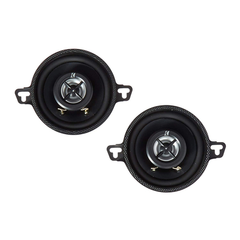
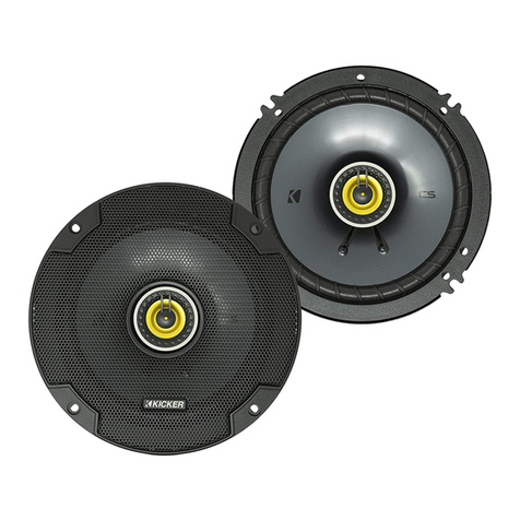
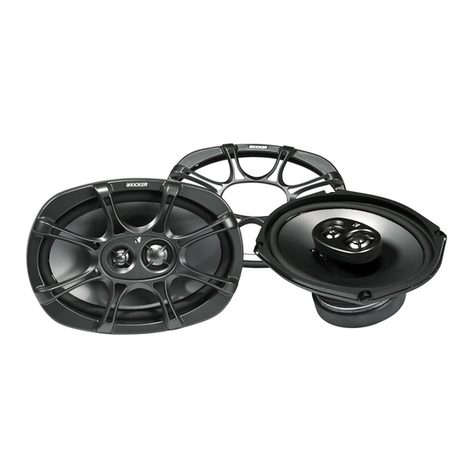
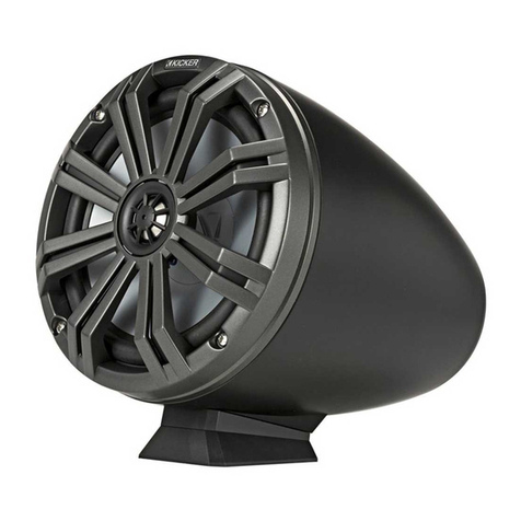
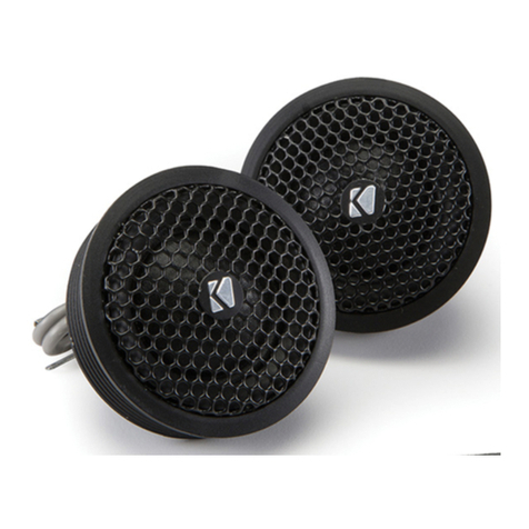
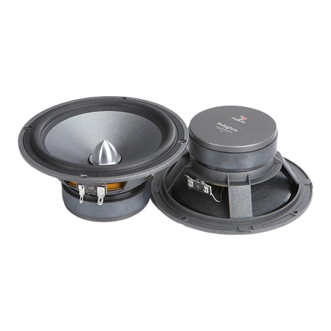
Kicker KSTweeters KS25 User manual

KS
KSTWEETERS
KS25, KS20, KS13
©2007 Stillwater Designs
English Version
Versión Español
Tweeters KS
Manual del Propietario
Deutsche Version
KS-Hochtöner
Benutzerhandbuch
Version Française
Haut-parleurs d’aigus KS
Manuel d'utilisation
2008 KS Tweeters 4in1 a01.qxp 11/29/2007 4:09 PM Page 1

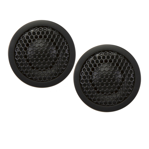
The Kicker KS series tweeters are specifically designed to bring out the high frequency
definition of your vehicle’s audio system. The KS tweeters can easily replace stock tweeters
in factory locations and offer several mounting options to deliver a wide range of
applications for custom installations.
Location
Your Kicker KS Tweeters can be mounted in several locations throughout your vehicle. The
easiest way to improve the high frequency response of your car stereo system is to replace
the OEM tweeters in their original factory location. There are several other places tweeters
can be custom mounted in your vehicle. The most common locations for tweeter mounting
are in the door, the sail panel, the dash, the kick panel, and in the A-pillars. See Figure 1.
Mounting the tweeter near the woofer maintains a more cohesive sonic response between
the lows and the highs, but tweeters are often mounted in a higher location in the vehicle to
elevate the sound stage.
INSTALLATION
Congratulations on your
KICKER purchase
Please record your purchase
information and keep your sales
receipt for validation of warranty.
Authorized Kicker Dealer:
Purchase Date:
Speaker Model Number:
_________________________
_________________________
_________________________
2
INSTALLATION
KSTweeters
Owner’sManual
KS25 /KS20 /KS13
Models:
KSTWEETERS 3
Figure 2
Flush Mount
SurfaceMount
Shorter
Mounting Nut
SurfaceMount Cup
Panel
Panel
Tweeter Flange
Tweeter
Tweeter
Figure 3
M3 Screw
TweeterMounting
The tweeter can be mounted one of three ways: flush, surface, and angled mounting. For
flush mounting applications, please refer to the illustration in Figure 2. Choose a flat location
on the panel with space behind the panel to allow room for the mounting nut and motor
structure. After checking the clearances, cut the recommended diameter mounting hole in
the panel. Position the shorter mounting nut behind the panel. Use the longer mounting nut
if the panel’s thickness prohibits the use of the shorter mounting nut. Feed the wire through
the optional tweeter flange, the hole in the panel, and the mounting nut. Mount the tweeter
by screwing the mounting nut onto the tweeter.
For surface mounting applications use the surface mount cup as a template and pre-drill
one 7/64” (2.5mm) screw hole for attaching the surface mount cup to the panel, and a
5/16” (8mm) hole for the wires. A M3 pan-cross head wood screw is supplied to attach the
surface mount cup to the panel. Position the tweeter over the surface mount cup and press
it into position. See Figure 3.
For angled mounting applications choose a flat location on the panel with space behind the
panel to allow room for the longer mounting nut and back angle ring. After checking the
clearances, cut the recommended diameter mounting hole in the panel. Place the front
angle ring (does not fit through the longer tweeter mounting nut) in front of the panel. Then
place the wire and tweeter through the tweeter flange, front angle ring, and into the panel.
Next place the wire through the back angle ring (fits through the longer mounting nut), place
the back angle ring over the rear of the tweeter, and line-up the narrow part of the front
angle ring for the preferred angle of operation. Place the wire through the longer mounting
nut and loosely tighten the mounting nut around the tweeter. Rotate all the parts in unison
until the tweeter is angled in the desired direction. Secure the assembly by tightening the
longer mounting nut. See Figure 4.
Figure 1
Sail
Panel
Door
Panel
Dash
A-Pillar
Kick
Panel
Factory Location
in DoorPanel
2008 KS Tweeters 4in1 a01.qxp 11/29/2007 4:09 PM Page 2

4 5
KSTWEETERS
INSTALLATION
PERFORMANCE
Figure 5
Wiring
Hooking up your Kicker KS tweeters is easy. Mount the external crossover in a location free
and clear of water and mechanical components of the vehicle with the enclosed phillips-
head wood screws. There are two lengths of wire attached to each end of the KS Series
Tweeter Crossover. The gray wire is positive and the black wire is negative. One set of wires
is labeled “INPUT” and is used to connect the source unit or amplifier to the crossover. The
other set of wires is labeled “KS TWEETER” and is intended to connect to the wires coming
off of the tweeter with the included red butt connectors. See Figure 5.
KS13
1/2 (13)
Kaladex
Neodymium
4 (3)
150 (75)
92
4500-21K
9/16 (14)
1 9/16 (4.0)
12, 4500
KS25
1 (25)
Aluminum
Neodymium
4 (3)
300 (150)
94
3500-20k
13/16 (21)
1 15/16 (4.9)
18, 4000
Performance
Model:
Tweeter Size, in (mm)
Dome Material
Magnet Type
Impedance ohms, Rated (DC Resistance)
Power Handling Watts, Peak (RMS)
Sensitivity [SPLo], dB @ 1W, 1m
Effective Frequency Range, Hz
Flush Mount Tweeter Depth, in (mm)
Flush Mount Tweeter Hole Diameter, in (cm)
High Pass, dB, at Frequency, Hz
KS20
3/4 (20)
Titanium
Neodymium
4 (3)
190 (95)
92
4500-21k
9/16 (14)
1 9/16 (4.0)
12, 4500
Note: All specifications and performance figures are subject to change. Please visit the www.kicker.com for the most current information.
To get the best performance from your new Kicker speakers, we recommend using genuine Kicker Accessories and Wiring.
Please allow two weeks of break-in time for the speaker to reach optimum performance.
Angled Mount
Longer
Mounting Nut
Back
Angle Ring
Front
Angle Ring
Panel
Tweeter
Flange
Tweeter
Figure 4
Pro Tip: You are one Kicker Loaded-Subwoofer enclosure, one ZX Mono-Amplifier and a few cables away from a slammin’
system! The Kicker ZX line of mono-amplifiers make it easy to upgrade to solid bass with your existing or stock source unit.
Please ask your dealer about the Kicker Comp and CompVR Subwoofer upgrades.
KS
Tweeter
KSSeries
Crossover
SourceUnit orAmplifier
+-
+
-
-
+
Red Butt
Connectors
WiringAdditionalTweeters
Modern high performance tweeters have a lower DC Resistance than what used to be
available. The Kicker KS-Series tweeters are rated at four ohms and work with any source
unit or amplifier designed to operate at a four ohm load. If you want to add additional KS-
Series tweeters to your existing component, coaxial, or tweeter system, on each channel of
your source unit or amplifier wire the tweeter crossover in series as shown below. This will
add more high frequency response while improving the sound quality, lowering the total
harmonic distortion, and decreasing the thermal load at the source unit or amplifier. This
may prevent an amplifier from shutting down due to over-current protection circuitry.
Figure 6
SourceUnit orAmplifier
KS
Tweeter
INPUT OUTPUT to
KSTweeter
Red Butt
Connectors
Series
Wiring
+
-
+
-
+
-
+
-
+
-
+
-
Red Butt
Connectors
KS
Tweeter
INPUT OUTPUT to
KSTweeter
2008 KS Tweeters 4in1 a01.qxp 11/29/2007 4:09 PM Page 3

Los tweeters de la serie KS han sido específicamente diseñados para sacar a relucir la
definición de alta frecuencia del sistema de sonido de su vehículo. Los tweeters KS pueden
reemplazar fácilmente los tweeters estándar en ubicaciones de fábrica y ofrecer una amplia
gama de aplicaciones para instalaciones personalizadas.
Ubicación
Los tweeters KS de Kicker se pueden montar en varias ubicaciones del vehículo. La mejor
manera de mejorar la respuesta de alta frecuencia del sistema estereofónico de su
automóvil es cambiar los tweeters estándar que hay en las ubicaciones de fábrica original.
Hay otros lugares donde los tweeters se pueden montar en ubicaciones personalizadas en
el vehículo. Las ubicaciones más comunes para montaje de tweeters son: la puerta, el
panel triangular, el tablero, el panel interno y los pilares A. Vea la Figura 1. Montar el tweeter
cerca del woofer mantiene una respuesta sónica más cohesiva entre los bajos y los altos,
pero los tweeters por lo general se montan en lugares altos del vehículo para elevar el
escenario de sonido.
INSTALACIÓN
¡Felicidades por su
compra de KICKER
Por favor registre su información de compra y
mantenga su recibo de ventas para
validación de la garantía.
Distribuidor autorizado
de Kicker:
Fecha de compra:
Número de modelo
del altavoz:
_________________________
_________________________
_________________________
6
INSTALACIÓN
Tweeters KS
Manual del propietario
KS25 /KS20 /KS13
Modelos:
7
Figura 2
Montajeal ras
Montajeen
superficie
Tuercade
montajecorta
Copademontajeen superficie
Panel
Panel
Rebordedetweeter
Tweeter
Tweeter
Figura 3
Tornillo M3
Montaje del tweeter
El tweeter se puede montar de tres maneras: al ras, en superficie y en ángulo.
Para las aplicaciones de montaje al ras, consulte la ilustración de la Figura 2. Seleccione
una parte plana del panel con espacio detrás para la estructura del motor y la tuerca de
montaje. Después de asegurarse de que haya espacio, haga un corte de 2 plg. (5.1 mm) de
diámetro en el panel. Ponga la tuerca de montaje corta detrás del panel. Use la tuerca de
montaje larga si el grosor del panel impide usar la corta. Pase el cable a través del reborde
opcional del tweeter, el agujero en el panel y la tuerca de montaje. Monte el tweeter
poniéndole y apretando la tuerca de montaje.
Para aplicaciones de montaje en superficie, use la copa de montaje en superficie como
plantilla y haga en el panel un agujero piloto de 7/64 de plg. (2.5 mm) para el tornillo de la
copa y un agujero de 5/16 de plg. (8 mm) para los cables. Se incluye un tornillo M3 para
madera de cabeza troncocónica con ranuras en cruz para fijar la copa en el panel. Coloque
el tweeter sobre la copa y presiónelo hasta que encaje en posición. Vea la Figura 3.
Para aplicaciones de montaje en ángulo, seleccione una parte plana del panel con espacio
detrás para la tuerca de montaje larga y el anillo angular trasero. Después de asegurarse de
que haya espacio, haga en el panel un agujero de montaje del diámetro recomendado.
Ponga el anillo angular delantero (el que no cabe a través de la tuerca de montaje larga del
tweeter) delante del panel. Luego, pase el cable y el tweeter a través del reborde de tweeter
y el anillo angular delantero hasta detrás del panel. A continuación, pase el cable a través
del anillo angular trasero (que cabe a través de la tuerca de montaje larga), coloque el anillo
angular trasero sobre la parte de atrás del tweeter y alinee la parte angosta del anillo
angular delantero para lograr el ángulo preferido de funcionamiento. Pase el cable a través
de la tuerca de montaje larga y ajústela en el tweeter sin apretarla. Haga girar las partes en
conjunto hasta que el tweeter quede en el ángulo deseado. Asegure el montaje apretando
la tuerca de montaje larga. Vea la Figura 4.
Figura 1
Panel
triangular
Panel de
la puerta
Tablero
Pilar A
Panel
interno
Ubicacióndefábricaen el
panel dela puerta
KSTWEETERS
2008 KS Tweeters 4in1 a01.qxp 11/29/2007 4:09 PM Page 4

8 9
INSTALACIÓN
RENDIMIENTO
Figura 5
Cableado
Es fácil conectar los tweeters de la serie KS de Kicker. Con los tornillos para madera de
cabeza Phillips que se incluyen, monte el crossover externo donde ni llegue agua ni haya
componentes mecánicos del vehículo. Hay dos cables unidos a cada uno de los extremos
del crossover de tweeter de la serie KS. El cable gris es positivo y el cable negro es
negativo. Con el conjunto de cables que dice INPUT se conecta la unidad fuente o
amplificador al crossover. El otro conjunto de cables dice KS TWEETER y es para
conectarlo a los cables que salen del tweeter con los conectores tubulares rojos que se
incluyen. Vea la Figura 5.
KS13
1/2 (13)
Kaladex
Neodimio
4 (3)
150 (75)
92
4500 a 21K
9/16 (14)
1 9/16 (4)
12, 4500
KS25
1 (25)
Aluminio
Neodimio
4 (3)
300 (150)
94
3500 a 20k
13/16 (21)
1 15/16 (4.9)
18, 4000
Rendimiento
Modelo:
Tamaño del tweeter, plg. (mm)
Material del domo
Tipo de imán
Impedancia en ohms, valor nominal (resistencia a la CC)
Procesamiento de potencia en W, máxima (RMS)
Sensibilidad [SPLo], dB a 1 W, 1 m
Gama efectiva de frecuencias, Hz
Profundidad de montaje al ras del tweeter, plg. (mm)
Diámetro del corte de montaje al ras del tweeter, plg. (cm)
Pasaaltas, dB, a la frecuencia, Hz
KS20
3/4 (20)
Titanio
Neodimio
4 (3)
190 (95)
92
4500 a 21k
9/16 (14)
1 9/16 (4)
12, 4500
Nota: Todas las especificaciones y cifras de rendimiento están sujetas a cambios.
Visite www.kicker.com para obtener la información más actual.
Para obtener el mejor rendimiento de sus nuevos altavoces Kicker, le recomendamos que use accesorios y cableado Kicker auténticos.
Deje pasar aproximadamente dos semanas para que el altavoz alcance su rendimiento óptimo.
Montaje
en ángulo
Tuercade
montajelarga
Anillo angular
trasero
Anillo angular
delantero
Panel
Rebordede
tweeter
Tweeter
Figura 4
Sugerencia profesional: A usted le falta nada más una caja de subwoofer cargado de Kicker, un monoamplificador ZX y
unos cables para tener un sistema atronador. La línea ZX de monoamplificadores Kicker facilita el mejoramiento a bajos
sólidos con su unidad fuente estándar o actual. Pregúntele a su distribuidor por los mejoramientos de subwoofer Comp y
CompVR de Kicker.
Tweeter KS
Crossover dela
serie KS
Unidad fuente o amplificador
+
-
+
-
-+
Conectores
tubulares rojos
Cableado de tweeters adicionales
Los tweeters modernos de alto rendimiento tienen menos resistencia a la CC que los de
antes. Los tweeters de la serie KS de Kicker tienen un valor nominal de 4 ohms y funcionan
con cualquier unidad fuente o amplificador diseñado para funcionar con 4 ohms de carga.
Si desea agregar tweeters de la serie KS a su sistema actual de tweeters, altavoces
coaxiales o altavoces componentes en cada canal de su unidad fuente o amplificador,
conecte el crossover de tweeter en serie como se muestra abajo. Esto mejora la calidad del
sonido, reduce la distorsión armónica total y disminuye la carga térmica en la unidad fuente
o amplificador. Esto puede evitar que el amplificador se apague a causa del circuito de
protección contra exceso de corriente.
Figura 6
Unidad fuente o amplificador
Tweeter KS
INPUT (entrada) OUTPUT(salida) al
Tweeter KS
Conectores
tubulares
rojos
Cableado
en serie
+
-
+
-
+
-
+
-
+
-
11052007-a+08KS
Tweeter KS
KSTWEETERS
2008 KS Tweeters 4in1 a01.qxp 11/29/2007 4:09 PM Page 5

Die Hochtöner der Kicker KS-Serie sind spezifisch darauf ausgelegt, die
Hochfrequenzdefinition Ihres Auto-Soundsystems zu verbessern. Die KS-Hochtöner können
einfach vorhandene Hochtöner an werksseitig vorgegebenen Stellen ersetzen und bieten
mehrere Einbauoptionen für ein breites Spektrum an Spezialinstallationen.
Platzierung
Ihre Kicker KS-Hochtöner können an mehreren Stellen in Ihrem Fahrzeug montiert werden.
Die einfachste Methode zur Verbesserung des Hochfrequenzbereichs Ihres Auto-
Soundsystems besteht darin, vorhandene Hochtöner an werksseitig vorgegebenen Stellen
zu ersetzen. Es gibt mehrere andere Stellen für eine Spezialinstallation der Hochtöner in
Ihrem Fahrzeug. Die am häufigsten verwendeten Stellen zum Einbau des Hochtöners sind in
der Tür, die Dreiecksabdeckung, das Armaturenbrett, die Einstiegsverkleidung und die A-
Säule. Siehe Abbildung 1. Der Einbau des Hochtöners in der Nähe des Tieftöners bietet
einen gleichmäßigeren Übergang zwischen niedrigen und hohen Tönen, aber Hochtöner
werden oft an einer höheren Stelle im Auto eingebaut, um die Klangbühne zu heben.
INSTALLATION
Autorisierter
Kicker-Händler:
Kaufdatum:
Lautsprecher-
Modellnummer:
_________________________
_________________________
_________________________
10
INSTALLATION
KS-Hochtöner
Benutzerhandbuch
KS25 /KS20 /KS13
Modelle:
KSTWEETERS 11
Abbildung 2
Bündiger
Einbau
Oberflächeneinbau
Kürzere
Befestigungsmutter
Oberflächeninstallationsbecher
Verkleidung
Verkleidung
Hochtöner-Flansch
Hochtöner
Hochtöner
Abbildung 3
M3-
Schraube
Hochtönereinbau
Der Hochtöner kann auf drei Arten eingebaut werden: bündig, auf Oberfläche und abgewinkelt.
Für den bündigen Einbau siehe Abbildung 2. Wählen Sie eine flache Stelle an der Verkleidung mit
Freiraum für die Befestigungsmutter und die Motorstruktur dahinter. Nachdem Sie den Freiraum
überprüft haben, schneiden Sie ein Loch mit dem empfohlenen Durchmesser in die Verkleidung.
Platzieren Sie die kürzere Befestigungsmutter hinter der Verkleidung. Verwenden Sie die längere
Befestigungsmutter, wenn die Dicke der Verkleidung den Einsatz der kürzeren verhindert. Führen
Sie den Draht durch den optionalen Hochtönerflansch, das Loch in der Verkleidung und die
Befestigungsmutter. Bauen Sie den Hochtöner ein, indem Sie die Befestigungsmutter am
Hochtöner anschrauben.
Verwenden Sie bei der Oberflächeninstallation den Oberflächeninstallationsbecher als Schablone
und bohren Sie ein 2,5-mm-Schraubloch für die Befestigung des Oberflächeninstallationsbechers
an der Verkleidung und ein 8-mm-Loch für die Drähte vor. Für die Befestigung des
Oberflächeninstallationsbechers an der Verkleidung liegt eine M3-Flachkopfschraube mit
Kreuzschlitz bei. Platzieren Sie den Hochtöner über dem Oberflächeninstallationsbecher und
drücken Sie ihn ein. Siehe Abbildung 3.
Beim abgewinkelten Einbau wählen Sie eine flache Stelle an der Verkleidung mit ausreichendem
Freiraum dahinter für die längere Befestigungsmutter und den hinteren Winkelring. Nachdem Sie
den Freiraum überprüft haben, schneiden Sie ein Loch mit dem empfohlenen Durchmesser in die
Verkleidung. Platzieren Sie den vorderen Winkelring (passt nicht durch die längere Hochtöner-
Befestigungsmutter) vor die Verkleidung. Führen Sie dann den Draht und den Hochtöner durch
Hochtönerflansch und vorderen Winkelring in die Verkleidung ein. Führen Sie dann den Draht
durch den hinteren Winkelring (passt durch die längere Befestigungsmutter), platzieren Sie den
hinteren Winkelring über die Rückseite des Hochtöners und richten Sie den schmalen Teil des
vorderen Winkelrings im gewünschten Betriebswinkel aus. Führen Sie den Draht durch die
längere Befestigungsmutter und ziehen Sie die Befestigungsmutter leicht um den Hochtöner
herum an. Drehen Sie alle Teile gleichzeitig, bis der Hochtöner in die gewünschte Richtung weist.
Sichern Sie die Baugruppe, indem Sie die längere Befestigungsmutter anziehen. Siehe Abbildung
4.
Abbildung 1
Dreiecksabdeckung
Türverkleidung
Armaturenbrett
A-Säule
Einstiegsverkleidung
Werksseitige Einbaustelle
in Türverkleidung
Herzlichen Glückwunsch zum
Kauf des KICKER
Bitte heben sie für Ihre Garantie den
Kassenzettel auf und tragen Sie die
Daten Ihres Einkaufs ein.
2008 KS Tweeters 4in1 a01.qxp 11/29/2007 4:09 PM Page 6

1213
KSTWEETERS
INSTALLATION
LEISTUNG
Abbildung 5
Verkabelung
Der Anschluss Ihrer Kicker KS-Hochtöner ist ganz einfach. Befestigen Sie die externe
Crossover-Einheit mit den beiliegenden Kreuzschlitzschrauben an einer von Wasser freien
und von den mechanischen Komponenten des Fahrzeugs entfernten Stelle. An jedem Ende
der KS-Hochtöner-Crossovers sind Kabel zweier verschiedener Längen angebracht. Das
graue Kabel ist positiv, das schwarze negativ. Eine Kabelgruppe ist mit „INPUT“ bezeichnet
und dient dazu, das Autoradio oder den Verstärker mit der Crossover-Einheit zu verbinden.
Die anderen Kabel tragen die Bezeichnung „KS TWEETER“ und müssen mit den
beiliegenden roten Kabelverbindern an die vom Hochtöner kommenden Kabel
angeschlossen werden. Siehe Abbildung 5..
KS13
1/2 (13)
Kaladex
Neodymium
4 (3)
150 (75)
92
4500-21k
9/16 (14)
1 9/16 (4)
12, 4500
KS25
1 (25)
Aluminium
Neodymium
4 (3)
300 (150)
94
3500-20k
13/16 (21)
1 15/16 (4,9)
18, 4000
Leistung
Modell:
Hochtönergröße, Zoll (mm)
Kalottenmaterial
Magnettyp
Nennimpedanz, Ohm (GS-Widerstand)
Spitzenbelastbarkeit, Watt (RMS)
Empfindlichkeit [SPLo], dB bei 1 W, 1 m
Effektiver Frequenzbereich, Hz
Bündige Tieftöner-Einbautiefe, Zoll (mm)
Tieftöner-Montagelochdurchmesser, bündig, Zoll (mm)
Hochpass, dB, bei Frequenz, Hz
KS20
3/4 (20)
Titan
Neodymium
4 (3)
190 (95)
92
4500-21k
9/16 (14)
1 9/16 (4)
12, 4500
Hinweis: Alle technischen Daten und Leistungswerte können sich ändern. Sie finden die aktuellen Informationen unter www.kicker.com.
Um das Maximum aus Ihren neuen Kicker-Lautsprechern herauszuholen, sollten Sie echtes Kicker-Zubehör und Kicker-Kabel verwenden.
Die Lautsprecher erreichen ihre optimale Leistung erst nach einer zweiwöchigen Einarbeitungszeit.
Abgewinkelter
Einbau
Längere
Befestigungsmutter
Hinterer
Winkelring
Vorderer
Winkelring
Verkleidung
Hochtöner-
Flansch
Hochtöner
Abbildung 4
Pro-Tipp: Sie sind nur ein Gehäuse mit Kicker-Subwoofer, einen ZX Mono-Verstärker und einige Kabel von einem
Wahnsinnssystem entfernt! Die Mono-Verstärker der Kicker ZX-Serie machen es einfach, bei Verwendung Ihres existierenden
Systems oder eines Standardsystems felsenfesten Bass zu bekommen. Erkundigen Sie sich bei Ihrem Händler nach Kicker
Comp- und CompVR-Subwoofer-Upgrades.
KS-
Hochtöner
KS-Crossover-Einheit
Autoradio oder Verstärker
+-
+
-
+
-
-
+
Rote
Kabelverbinder
Anschluss weiterer Hochtöner
Moderne Hochleistungs-Hochtöner haben einen geringeren Gleichstrom-Widerstand, als
dies früher der Fall war. Die Kicker KS-Hochtöner haben eine Impedanz von 4 Ohm und
können mit jedem Autoradio oder Verstärker zusammenarbeiten, der auf 4 Ohm ausgelegt
ist. Wenn Sie weitere Kicker KS-Hochtöner zu Ihren existierenden Komponenten-, Koaxial-
oder Hochtönerlautsprechern hinzufügen wollen, schalten Sie an jedem Kanal Ihres
Autoradios oder Verstärkers die Hochtöner-Crossover-Einheit wie unten gezeigt in Reihe.
Dies verbessert den Hochfrequenzbereich und die Soundqualität, verringert den Klirrfaktor
und verringert die Wärmebelastung am Autoradio oder Verstärker. Dies kann verhindern,
dass sich der Verstärker aufgrund einer Überlastschaltung ausschaltet.
Abbildung 6
Autoradio oder Verstärker
KS-
Hochtöner
EINGANG AUSGANG an
KS-Hochtöner
Rote
Kabelverbinder
Reihenanschluss
+
-
+
-
+
-
+
-
+
-
11052007-a+08KS
KS-
Hochtöner
2008 KS Tweeters 4in1 a01.qxp 11/29/2007 4:09 PM Page 7

Les haut-parleurs d’aigus Kicker KS ont été spécialement conçus pour faire ressortir les
hautes fréquences du système de sonorisation de votre véhicule. Ils peuvent facilement
remplacer les haut-parleurs d’aigus d’origine dans les emplacements standard, et ils offrent
plusieurs options de montage permettant une grande variété d’installations sur mesure.
Emplacement
Plusieurs emplacements de montage sont possibles dans le véhicule pour les haut-parleurs
d’aigus Kicker KS. La façon la plus simple d’améliorer la réponse dans les hautes fréquences du
système stéréophonique du véhicule est de remplacer les haut-parleurs d’aigus d’origine en
utilisant les emplacements standard. Plusieurs autres emplacements de montage sur mesure
des haut-parleurs d’aigus sont possibles dans le véhicule. Les plus courants sont la portière, le
panneau de custode, la tableau de bord, le panneau de seuil de portière et les montants de
pare-brise. Voir la figure 1. Bien qu’un montage du haut-parleur d’aigus près du haut-parleur de
graves permette de maintenir une réponse acoustique plus cohérente entre les graves et les
aigus, les haut-parleurs d’aigus sont souvent montés plus haut dans le véhicule afin d’élever
l’image sonore.
INSTALLATION
Revendeur agréé Kicker :
Date d’achat :
Numéro de modèle
du haut-parleur :
_________________________
_________________________
_________________________
14
INSTALLATION
Haut-parleurs d’aigus KS
Manuel d’utilisation
KS25 /KS20 /KS13
Modèles :
15
Figure 2
Montage
encastré
Montage
en surface
Baguede
montage courte
Coupelle demontage en surface
Panneau
Panneau
Haut-parleurd’aigus
Haut-parleurd’aigus
Haut-parleurd’aigus
Figure 3
Vis M3
Montage des haut-parleurs d’aigus
Le montage des haut-parleurs d’aigus peut se faire de trois façons : encastré, en surface et
incliné. Pour le montage encastré, reportez-vous à l’illustration de la figure 2. Choisissez un
emplacement plat sur le panneau, avec suffisamment de place sous celui-ci pour la bague
de montage et le moteur. Après avoir vérifié l’espace disponible, découpez dans le panneau
un trou de montage du diamètre préconisé. Mettez en place la bague de montage courte
sous le panneau. Utilisez la bague de montage longue si l’épaisseur du panneau ne permet
pas l’utilisation de la bague de montage courte. Passez les fils dans l’enjoliveur facultatif, le
trou du panneau et la bague de montage. Fixez le haut-parleur d’aigus en serrant la bague
de montage sur le haut-parleur d’aigus.
Pour un montage en surface, utilisez la coupelle de montage en surface comme gabarit et
percez un trou de 2,5 mm pour la fixation de la coupelle au panneau, et un trou de 8 mm
pour les fils. Une vis à bois M3 à tête cruciforme est fournie pour la fixation de la coupelle
de montage en surface au panneau. Mettez le haut-parleur d’aigus sur la coupelle de
montage en surface et appuyez pour le mettre en place. Voir la figure 3.
Pour un montage incliné, choisissez un emplacement plat sur le panneau, avec
suffisamment de place sous celui-ci pour la bague de montage longue et la bague
d’inclinaison arrière. Après avoir vérifié l’espace disponible, découpez dans le panneau un
trou de montage du diamètre préconisé. Mettez la bague d’inclinaison avant (celle qui ne
rentre pas sur la bague de montage longue) à l’avant du panneau. Puis insérez les fils et le
haut-parleur d’aigus dans l’enjoliveur de haut-parleur d’aigus, la bague d’inclinaison avant et
le panneau. Insérez ensuite les fils dans la bague d’inclinaison arrière (celle qui rentre sur la
bague de montage longue), mettez la bague d’inclinaison arrière sur l’arrière du haut-parleur
d’aigus, et orientez la partie mince de la bague d’inclinaison avant de façon à obtenir l’angle
d’inclinaison voulu. Passez les fils dans la bague de montage longue et vissez celle-ci sur le
haut-parleur d’aigus sans serrer. Faites tourner toutes les pièces en même temps de façon
à ce que le haut-parleur soit orienté dans la direction voulue. Fixez l’ensemble en serrant la
bague de montage longue. Voir la figure 4.
Figure 1
Panneau de
custode
Garniture de
portière
Tableau de
bord
Montant depare-brise
Panneau de
seuil deportière
Emplacement standard dans
la garniture deportière
Félicitations pour votre achat
KICKER
Prière de registrer vos informations d'achat
et de garder le ticket de caisse pour valider
votre garantie.
KSTWEETERS
2008 KS Tweeters 4in1 a01.qxp 11/29/2007 4:09 PM Page 8

16 17
KSTWEETERS
INSTALLATION
PERFORMANCES
Figure 5
Raccordement
Le raccordement des haut-parleurs d’aigus Kicker KS est facile. À l’aide des vis à
bois cruciformes fournies, montez le filtre externe en un endroit sec sans
composants mécaniques. Deux fils sortent de chacune des extrémités du filtre du
haut-parleur d’aigus KS. Le fil gris est positif est le noir est négatif. Le jeu de fils
repéré « INPUT » (entrée) sert au raccordement de l’appareil source ou de
l’amplificateur au filtre. L’autre jeu de fils, repéré « KS TWEETER » (haut-parleur
d’aigus KS) sert à raccorder les fils sortant du haut-parleur d’aigus à l’aide des
connecteurs à manchon rouge. Voir la figure 5.
KS13
1/2 (13)
Kaladex
Néodyme
4 (3)
150 (75)
92
4500-21K
9/16 (14)
1 9/16 (4)
12, 4500
KS25
1 (25)
Aluminum
Néodyme
4 (3)
300 (150)
94
3500-20k
13/16 (21)
1 15/16 (4,9)
18, 4000
Performances
Modèle :
Diamètre du haut-parleur d’aigus, pouces (mm)
Matériau du dôme
Type d’aimant
Impédance nominale, ohms (résistance c.c.)
Puissance admissible, watts, crête (efficace)
Sensibilité [SPLo], dB pour 1 W à 1 m
Plage de fréquence effective, Hz
Profondeur de montage encastré du haut-parleur d’aigus, pouces (mm)
Diamètre du trou de montage encastré du haut-parleur d’aigus, pouces (cm)
Filtrage passe-haut, dB, pour fréquence, Hz
KS20
3/4 (20)
Titane
Néodyme
4 (3)
190 (95)
92
4500-21k
9/16 (14)
1 9/16 (4)
12, 4500
Remarque : Toutes les caractéristiques techniques et données de fonctionnement sont susceptibles de modifications sans préavis. Pour
obtenir les informations les plus récentes, visitez le site www.kicker.com.
Pour obtenir les meilleures performances des haut-parleurs Kicker, il est conseillé d’utiliser des accessoires et fils Kicker d’origine.
Laissez aux haut-parleurs un temps d’adaptation d’environ deux semaines pour qu’ils atteignent leurs performances optimales.
Montage
incliné
Baguede
montage longue
Bagued’inclinaison
arrière
Bague
d’inclinaisonavant
Panneau
Enjoliveurdehaut-
parleurd’aigus
Haut-parleurd’aigus
Figure 4
Conseil pro : Il ne vous manque qu’un caisson de graves Kicker, l’amplificateur monophonique ZX et quelques câbles pour
obtenir un système percutant ! La gamme d’amplificateurs monophoniques Kicker ZX permet de tirer des graves robustes d’un
appareil source existant ou standard. Demandez à votre revendeur de vous conseiller sur les caissons de graves Kicker Comp
et CompVR.
Haut-parleur
d’aigusKS
Sortie vers
haut-parleur
d’aigusKS
Appareil sourceou amplificateur
+-
+
-
+
-
-
+
Connecteurs à
manchonrouge
Raccordement de haut-parleurs d’aigus supplémentaires
La résistance c.c. des haut-parleurs d’aigus modernes à hautes performances est inférieure à ce
qui existait auparavant. Les haut-parleurs d’aigus Kicker KS ont une résistance de 4 ohms et
peuvent fonctionner sur tout appareil source ou amplificateur conçu pour une charge de 4 ohms.
Pour ajouter des haut-parleurs d’aigus KS supplémentaires à votre système existant de haut-
parleurs d’aigus, haut-parleurs coaxiaux ou à composants, raccordez le filtre de haut-parleur
d’aigus à chaque canal de l’appareil source ou de l’amplificateur, comme indiqué ci-dessous. La
réponse aux hautes fréquences est alors plus importante, tandis que la qualité sonore est
améliorée et que la distorsion harmonique totale ainsi que la charge thermique vue par l’appareil
source ou l’amplificateur sont réduites. Cela peut empêcher la mise hors tension de
l’amplificateur provoquée par le circuit de protection contre la surintensité.
Figure 6
Appareil sourceou amplificateur
Haut-parleur
d’aigusKS
ENTRÉE Sortie vers haut-
parleurd’aigusKS
Connecteurs
à manchon
rouge
Raccordement
série
+
-
+
-
+
-
+
-
+
-
11052007-i+08KS
Haut-parleur
d’aigusKS
2008 KS Tweeters 4in1 a01.qxp 11/29/2007 4:09 PM Page 9

KSTWEETERS
18 19
11292007-a+08KS
P.O. Box 459 • Stillwater, Oklahoma 74076 • U.S.A. • (405) 624-8510
AcousticsLimitedWarranty
Kicker warrants this product to be free from defects in material and workmanship under normal use for a period of
THREE (3) MONTHS from date of original purchase with receipt. When purchased from an Authorized KICKER Dealer
it is warranted for ONE (1) YEAR from date of original purchase with receipt. In all cases you must have the original
receipt. Should service be necessary under this warranty for any reason due to manufacturing defect or malfunction
during the warranty period, Kicker will repair or replace (at its discretion) the defective merchandise with equivalent
merchandise at no charge. Warranty replacements may have cosmetic scratches and blemishes. Discontinued
products may be replaced with more current equivalent products.
This warranty is valid only for the original purchaser and is not extended to owners of the product subsequent to the
original purchaser. Any applicable implied warranties are limited in duration to a period of the express warranty as
provided herein beginning with the date of the original purchase at retail, and no warranties, whether express or
implied, shall apply to this product thereafter. Some states do not allow limitations on implied warranties; therefore
these exclusions may not apply to you. This warranty gives you specific legal rights; however you may have other
rights that vary from state to state.
WHAT TO DO IF YOU NEEDWARRANTY OR SERVICE
Defective merchandise should be returned to your local Authorized Stillwater Designs (Kicker) Dealer for warranty
service. Assistance in locating an Authorized Dealer can be found at www.kicker.com or by contacting Stillwater
Designs directly. You can confirm that a dealer is authorized by asking to see a current authorized dealer window
decal.
If it becomes necessary for you to return defective merchandise directly to Stillwater Designs (Kicker), call the Kicker
Customer Service Department at (405) 624-8510 for a Return Merchandise Authorization (RMA) number. Package all
defective items in the original container or in a package that will prevent shipping damage, and return to:
Stillwater Designs, 5021 North Perkins Road, Stillwater, OK 74075
The RMA number must be clearly marked on the outside of the package. Please return only defective components.
The return of functioning items increases your return freight charges. Non-defective items will be returned freight-
collect to you.
Include a copy of the original receipt with the purchase date clearly visible, and a "proof-of-purchase" statement listing
the Customer's name, Dealer's name and invoice number, and product purchased. Warranty expiration on items
without proof-of-purchase will be determined from the type of sale and manufacturing date code. Freight must be
prepaid; items sent freight-collect, or COD, will be refused.
WHAT ISNOT COVERED?
This warranty is valid only if the product is used for the purpose for which it was designed.
It does not cover:
o Damage due to improper installation
o Subsequent damage to other components
o Damage caused by exposure to moisture, excessive heat, chemical cleaners, and/or UV radiation
o Damage through negligence, misuse, accident or abuse. Repeated returns for the same damage may be
considered abuse
o Any cost or expense related to the removal or reinstallation of product
o Speakers damaged due to amplifier clipping or distortion
o Items previously repaired or modified by any unauthorized repair facility
o Return shipping on non-defective items
o Products with tampered or missing barcode labels
o Products returned without a Return Merchandise Authorization (RMA) number
o Freight Damage
o The cost of shipping product to Kicker
o Service performed by anyone other than Kicker
HOW LONG WILL IT TAKE?
Kicker strives to maintain a goal of 24-hour service for all acoustics (subwoofers, midrange and coaxial drivers,
tweeters, crossovers, etc) returns. Delays may be incurred if lack of replacement inventory or parts is encountered.
Failure to follow these steps may void your warranty. Any questions can be directed to the Kicker Customer Service
Department at (405) 624-8510.
InternationalWarranty
Contact your International Kicker dealer or distributor concerning specific procedures for your country's warranty
policies.
WARNING: KICKER products are capable of producing sound levels that can permanently damage your hearing!
Turning up a system to a level that has audible distortion is more damaging to your ears than listening to an
undistorted system at the same volume level. The threshold of pain is always an indicator that the sound level is too
loud and may permanently damage your hearing. Please use common sense when controlling volume.
GARANTÍA INTERNACIONAL VersiónEspañol
Comuníquese con su concesionario o distribuidor Kicker internacional para obtener infor ación sobre procedimientos
específicos relacionados con las normas de garantía de su país.
ADVERTENCIA: Los excitadores Kicker son capaces de producir niveles de sonido que pueden dañar
permanentemente el oído. Subir el volumen del sistema hasta un nivel que produzca distorsión es más dañino para el
oído que escuchar un sistema sin distorsión al mismo volumen. El dolor es siempre una indicación de que el sonido es
muy fuerte y que puede dañar permanentemente el oído. Sea precavido cuando controle el volumen.
La frase "combustible para vivir la vida Livin' Loud™ a todo volumen" se refiere al entusiasmo por la vida que la marca
Kicker de estéreos de automóvil representa y a la recomendación a nuestros clientes de que vivan lo mejor posible ("a
todo volumen") en todo sentido. La línea de altavoces y amplificadores Kicker es la mejor del mercado de audio de
automóviles y por lo tanto representa el "combustible" para vivir a todo volumen en el área de "estéreos de automóvil"
de la vida de nuestros clientes. Recomendamos a todos nuestros clientes que obedezcan todas las reglas y
reglamentos locales sobre ruido en cuanto a los niveles legales y apropiados de audición fuera del vehículo.
INTERNATIONALE GARANTIE DeutscheVersion
Nehmen Sie mit Ihren internationalen Kicker-Fachhändler oder Vertrieb Kontakt auf, um Details über die
Garantieleistungen in Ihrem Land zu erfahren.
WARNUNG: KICKER-Treiber können einen Schallpegel erzeugen, der zu permanenten Gehörschäden führen kann!
Wenn Sie ein System auf einen Pegel stellen, der hörbare Verzerrungen erzeugt, schadet das Ihren Ohren mehr, als ein
nicht verzerrtes System auf dem gleichen Lautstärkepegel. Die Schmerzschwelle ist immer eine Anzeige dafür, dass
der Schallpegel zu laut ist und zu permanenten Gehörschäden führen kann. Seien Sie bei der Lautstärkeeinstellung
bitte vernünftig!
Der Slogan "Treibstoff für Livin' Loud" bezieht sich auf die mit den Kicker-Autostereosystemen assoziierte
Lebensfreude und die Tatsache, dass wir unsere Kunden ermutigen, in allen Aspekten ihres Lebens nach dem Besten
("Livin' Loud") zu streben. Die Lautsprecher und Verstärker von Kicker sind auf dem Markt für Auto-Soundsysteme
führend und stellen somit den "Treibstoff" für das Autostereoerlebnis unserer Kunden dar. Wir empfehlen allen unseren
Kunden, sich bezüglich der zugelassenen und passenden Lautstärkepegel außerhalb des Autos an die örtlichen
Lärmvorschriften zu halten.
GARANTIE INTERNATIONALE VersionFrançaise
Pour connaître les procédures propres à la politique de garantie de votre pays, contactez votre revendeur ou
distributeur International Kicker.
AVERTISSEMENT: Les haut-parleurs Kicker ont la capacité de produire des niveaux sonores pouvant endommager
l'ouïe de façon irréversible ! L'augmentation du volume d'un système jusqu'à un niveau présentant une distorsion
audible endommage davantage l'ouïe que l'écoute d'un système sans distorsion au même volume. Le seuil de la
douleur est toujours le signe que le niveau sonore est trop élevé et risque d'endommager l'ouïe de façon irréversible.
Réglez le volume en faisant prevue de bon sens !
L'expression " carburant pour vivre plein pot " fait référence au dynamisme de la marque Kicker d'équipements audio
pour véhicules et a pour but d'encourager nos clients à faire le maximum (" vivre plein pot ") dans tous les aspects de
leur vie. Les haut-parleurs et amplificateurs Kicker sont les meilleurs dans le domaine des équipements audio et
représentent donc pour nos client le " carburant pour vivre plein pot " dans l'aspect " installation audio de véhicule "
de leur vie. Nous encourageons tous nos clients à respecter toutes les lois et réglementations locales relatives aux
niveaux sonores acceptables à l'extérieur des véhicules.
GARANTIE
WARRANTY
2008 KS Tweeters 4in1 a01.qxp 11/29/2007 4:09 PM Page 10
This manual suits for next models
2
Table of contents
Languages:
Other Kicker Car Speakers manuals

Kicker
Kicker KS35 User manual

Kicker
Kicker KSTweeters KS13 User manual

Kicker
Kicker RMB6 User manual

Kicker
Kicker QSS674 User manual

Kicker
Kicker KST20 User manual

Kicker
Kicker KS35 User manual

Kicker
Kicker KS35 User manual

Kicker
Kicker SS56.2 User manual

Kicker
Kicker KMT60 User manual

Kicker
Kicker PS692 User manual

Kicker
Kicker RS56.2 User manual

Kicker
Kicker CSS65 User manual

Kicker
Kicker KS6930 User manual

Kicker
Kicker DS35 User manual

Kicker
Kicker DS7130 User manual

Kicker
Kicker KS350 User manual

Kicker
Kicker CS Series User manual

Kicker
Kicker CST20 User manual

Kicker
Kicker KSTweeters KS13 User manual

Kicker
Kicker KS5.2 User manual