manuals.online logo
Brands
  1. Home
  2. •
  3. Brands
  4. •
  5. Kicker
  6. •
  7. Car Speakers
  8. •
  9. Kicker KS5.2 User manual

Kicker KS5.2 User manual

KS COMPONENTS
KS5.2 KS6.2 KS65.2
English Version
Versión Español
Altavoz Componentes KS
Manual del Propietario
Deutsche Version
KS Komponenten-System
Benutzerhandbuch
Version Française
Haut-parleurs Composants KS
Manuel d'utilisation
KS
LIVIN’ LOUD
2011 KS Components Multilingual d01.indd 1 8/4/2010 11:04:51 AM
2KS Component Speakers
KS Component Speakers
Owner’s Manual
KS COMPONENT SPEAKERS
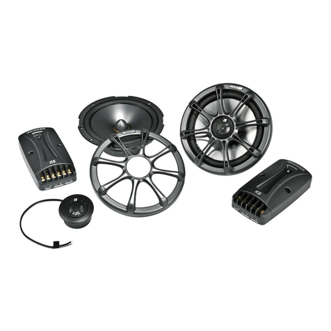
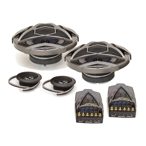
The KICKER KS Speakers offer an excellent upgrade to your vehicle’s factory sound system, delivering
great full-range sound at an amazing value! Their high-efficiency design means less power is needed
to play your music, while our use of advanced materials and construction techniques ensures optimal
performance for years to come.
Authorized KICKER Dealer:
Purchase Date:
Speaker Model Number:
Model: KS5.2 KS6.2 KS65.2
Woofer Size, in (mm) 5-1/4 (130) 6 (160) 6-1/2 (165)
Tweeter Size, in (mm) 1 (25) 1 (25) 1 (25)
Dome Material Titanium Titanium Titanium
Rated Impedance, ohm (DC Resistance, ohm) 4 (3.3) 4 (2.9) 4 (2.9)
Power Handling Watts, Peak (RMS) 130 (65) 150 (75) 150 (75)
Sensitivity [SPLo], dB @ 1W, 1m 88 88 88
Effective Frequency Range, Hz 38-21k 35-21k 35-21k
Woofer Mounting Hole Diameter, in (mm) 4-9/16 (116) 5 (127) 5-5/8 (143)
Woofer Bottom Mount Depth, in (mm) 2 (51) 1 15/16 (49) 2 1/8 (54)
Flush Mounting Tweeter Hole Diameter, in (mm) 1-15/16 (49) 1-15/16 (49) 1-15/16 (49)
Flush Mount Tweeter Depth, in (mm) 13/16 (21) 13/16 (21) 13/16 (21)
High Pass, dB, at Frequency, Hz 12, 4000 12, 4000 12, 4000
Low Pass, dB, at Frequency, Hz 12, 4000 12, 4000 12, 4000
High Frequency Output Attenuation, dB 0, 4.5, 9 0, 4.5, 9 0, 4.5, 9
Grilles Yes Yes Yes
MODEL: KS5.2 / KS6.2 / KS65.2
PERFORMANCE
WIRING
We recommend using 16 gauge (or larger) wire. The KS Speakers are rated at 4 ohms and work with
any source unit or amplifier designed to operate at a 4 ohm load. Make sure your source unit or
amplifier is rated for 4 ohm operation.
2011 KS Components Multilingual d01.indd 2 8/4/2010 11:05:04 AM
3
+
-
+
+
-
-+
-+
-
CH1 OUTPUT
INPUT MID TWEETER
+
+
-
-
+
-+
-+
-
INPUT MID TWEETER
+
-
+
-
+
+
+
-
-
-+
-+
-
CH1 OUTPUT
INPUT MID TWEETER
Crossover in 2-way configuration | One component set per channel
• At least two amplifier channels are needed for stereo operation (only one channel is shown)
Crossover in 2-way configuration | Two component sets per channel
• Requires two complete KS systems (four woofers, four tweeters, four crossovers)
• At least two amplifier channels are needed for stereo operation (only one channel is shown)
• Crossovers wired in parallel. Make sure your source unit or amplifier is rated for 2 ohm
operation.
tweeter
tweeter
tweeter
crossover
crossovercrossover
woofer
woofer
woofer
source unit / amplifier
Higher switch settings
will result in more volume
from the tweeter.
2011 KS Components Multilingual d01.indd 3 8/4/2010 11:05:05 AM

4KS Component Speakers
WOOFER MOUNTING
The KICKER KS Speakers are designed for free-air applications and do not require a sealed enclosure for
optimum performance. It is important to isolate the sound coming from the front of the speaker from the
sound radiating from the back of the speaker. This is most easily accomplished by mounting the speakers
in a vehicle’s factory locations or in a location with a semi-isolated rear chamber (like the rear deck of a
car behind the rear seats).
If you are replacing factory speakers in their original locations, you may have to enlarge the speaker
cut-outs and pre-drill new screw holes using a 7/64” (2.5mm) bit. Custom mounting locations will require
more preparation and work. Make sure that the speaker will not interfere with trunk and door opening and
closing mechanisms and that the enclosed screws will not puncture the fuel tank, puncture wiring, or
interfere with any other mechanical parts on the underside of the mounting surface. Cycle the windows all
the way down and up.
If the speaker cut-out locations require you to cut metal, avoid structural metal and braces. If the door
body and panel cannot support the weight of the speaker, an optional reinforcing ring (thin piece of wood
or Medium Density Fiberboard) may be fastened or adhered to the door body. Mount the speaker to the
vehicle as outlined in Fig. 4.
door body
door panel
speaker cut-out
KS woofer
mounting ring
(KS 5.2 only)
KS grille
mounting ring
reinforcing ring (optional)
Fig. 4
2011 KS Components Multilingual d01.indd 4 8/4/2010 11:05:05 AM
5
Fig. 5
Flush Mounting
Fig. 6
Angle Mounting
Fig. 7
Surface Mounting
TWEETER MOUNTING
The tweeter can be mounted one of three ways: flush, angled and surface. For flush mounting
applications, see Fig. 5. Choose a flat location on the panel with space behind the panel to allow room
for the short mounting nut, motor structure, and tweeter. After checking the clearances, cut a 1-3/4”
(44mm) diameter mounting hole in the panel. Position the short mounting nut behind the panel. Feed the
wire through the optional flush ring, the hole in the panel, and the mounting nut. Mount the tweeter by
screwing the mounting nut onto the tweeter.
For angled mounting applications choose a flat location on the panel with space behind the panel to allow
room for the long mounting nut, motor structure, tweeter post, and back angle ring. After checking the
clearances, cut a 1-3/4” (44mm) diameter mounting hole in the panel. Place the front angle ring in front of
the panel. Then place the wire and tweeter through the front angle ring and into the panel. Next, place the
wire through the back angle ring, place the back angle ring over the rear of the tweeter, and line-up the
narrow part of the front angle ring for the preferred angle of operation. Place the wire through the mounting
nut and loosely tighten the mounting nut around the tweeter. Rotate all the parts in unison until the tweeter
is angled in the desired direction. Secure the assembly by tightening the mounting nut. See Fig. 6.
For surface mounting applications use the surface mount cup as a template and pre-drill one 7/64”
(2.5mm) screw hole (using two holes is optional) for attaching the surface mount cup to the panel and
a 5/16” (8mm) hole for the wires. An M3 pan-cross head wood screw is supplied to attach the surface
mount cup to the panel. Position the tweeter over the surface mount cup and screw it into position. See
Fig. 7.
panel
panel
panel
short mounting nut
flush ring
flush ring
tweeter
tweeter
tweeter
long mounting nut
back angle ring
front angle ring
rounded surface
inset surface
surface mount cup
2011 KS Components Multilingual d01.indd 5 8/4/2010 11:05:06 AM

Other manuals for KS5.2

2

This manual suits for next models

2

Other Kicker Car Speakers manuals

Kicker KS650.2 User manual

Kicker

Kicker KS650.2 User manual

Kicker KMFC65 User manual

Kicker

Kicker KMFC65 User manual

Kicker RMB6 User manual

Kicker

Kicker RMB6 User manual

Kicker SS56.2 User manual

Kicker

Kicker SS56.2 User manual

Kicker QSS674 User manual

Kicker

Kicker QSS674 User manual

Kicker KSTweeters KS13 User manual

Kicker

Kicker KSTweeters KS13 User manual

Kicker KSTweeters KS25 User manual

Kicker

Kicker KSTweeters KS25 User manual

Kicker RS56.2 User manual

Kicker

Kicker RS56.2 User manual

Kicker KS35 User manual

Kicker

Kicker KS35 User manual

Kicker KS5.2 User manual

Kicker

Kicker KS5.2 User manual

Kicker CS Series User manual

Kicker

Kicker CS Series User manual

Kicker DS35 User manual

Kicker

Kicker DS35 User manual

Kicker CST20 User manual

Kicker

Kicker CST20 User manual

Kicker DS35 User manual

Kicker

Kicker DS35 User manual

Kicker KSC35 User manual

Kicker

Kicker KSC35 User manual

Kicker KS6930 User manual

Kicker

Kicker KS6930 User manual

Kicker DS7130 User manual

Kicker

Kicker DS7130 User manual

Kicker KS35 User manual

Kicker

Kicker KS35 User manual

Kicker KMT60 User manual

Kicker

Kicker KMT60 User manual

Kicker KS Series User manual

Kicker

Kicker KS Series User manual

Kicker KST20 User manual

Kicker

Kicker KST20 User manual

Kicker CSS65 User manual

Kicker

Kicker CSS65 User manual

Kicker KS350 User manual

Kicker

Kicker KS350 User manual

Kicker KS35 User manual

Kicker

Kicker KS35 User manual

Popular Car Speakers manuals by other brands

Audiopipe TXX-APA-12BL user manual

Audiopipe

Audiopipe TXX-APA-12BL user manual

Bazooka RS10A-hp installation manual

Bazooka

Bazooka RS10A-hp installation manual

Hertz MILLE PRO owner's manual

Hertz

Hertz MILLE PRO owner's manual

Blaupunkt GTt 300 OPERATING AND INSTALLATION Manual

Blaupunkt

Blaupunkt GTt 300 OPERATING AND INSTALLATION Manual

Boston Acoustics SX55 Specifications

Boston Acoustics

Boston Acoustics SX55 Specifications

Kenwood KFC-W212 Service manual

Kenwood

Kenwood KFC-W212 Service manual

VR3 Elite VRS653 installation manual

VR3

VR3 Elite VRS653 installation manual

Premier TS-W3001D4 Specifications

Premier

Premier TS-W3001D4 Specifications

Infinity 6530cx installation manual

Infinity

Infinity 6530cx installation manual

Blaupunkt GTx Series manual

Blaupunkt

Blaupunkt GTx Series manual

Focal K2 Power 165 KRX3 Specification sheet

Focal

Focal K2 Power 165 KRX3 Specification sheet

Precision Power PPI4.2 owner's manual

Precision Power

Precision Power PPI4.2 owner's manual

Jensen XS Series instruction sheet

Jensen

Jensen XS Series instruction sheet

AudioBahn AT60 operating instructions

AudioBahn

AudioBahn AT60 operating instructions

Focal BombA 27 V1 user manual

Focal

Focal BombA 27 V1 user manual

Blueant S1 user manual

Blueant

Blueant S1 user manual

Naxa NCS-768 Installation diagram

Naxa

Naxa NCS-768 Installation diagram

Focal Polyglass 130 VRS user manual

Focal

Focal Polyglass 130 VRS user manual

manuals.online logo
manuals.online logoBrands
  • About & Mission
  • Contact us
  • Privacy Policy
  • Terms and Conditions

Copyright 2025 Manuals.Online. All Rights Reserved.