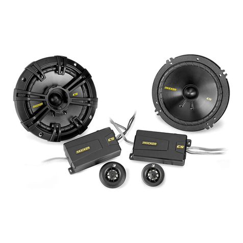
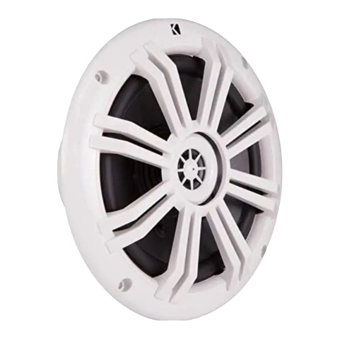
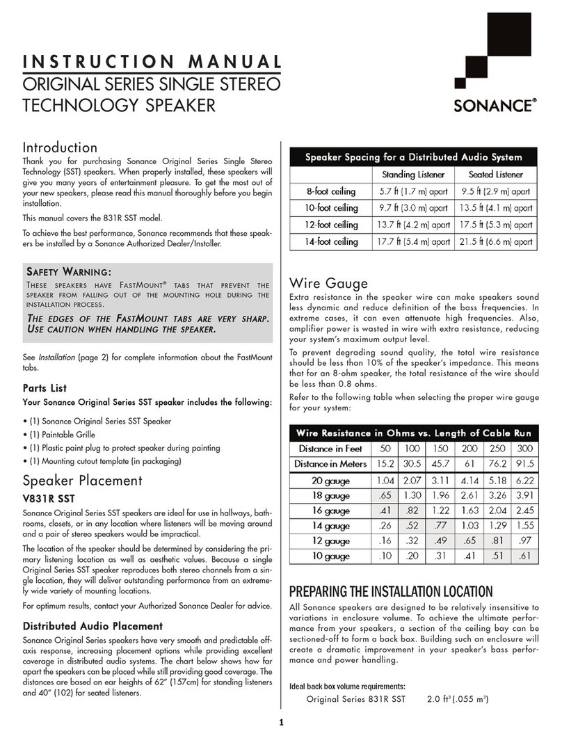
Kicker K35 User manual

Kicker Coaxial Speakers
Recommended Applications / Version 2.0
June 13, 2002
Kicker Coaxial
Technical Manual

FEATURES
• KALADEX Dome Tweeter with Neodymium Magnet We use Kaladex domes in the tweeters due to their
unparalleled strength and neodymium magnets to decrease the overall size of the tweeter. Since the Kaladex
domes are extremely stiff, they can withstand pressure that could damage other materials. And most important of
all, Kaladex domes have a very smooth high frequency response. The neodymium magnet has one of the greatest
strength to size ratio. The neodymium allows us to make the tweeter smaller without sacrificing the power han-
dling. The combination of these materials give the new Kicker Coaxials the edge needed to be Livin Loud’
• Ferro-Fluid™ Cooled Tweeter Voice Coil Ferrofluid is used to conduct heat away from the voice coil to the
magnet assembly. Ferro-fluid is a much better conductor than air. It helps keep the coil cooler than relying on just
air.
• CIMP (Curvilinear Injection-Molded Polygraphite) Woofer Cones The curvilinear shape of the cone
adds strength and prevents flexing under high excursion for maximum undistorted output. Utilizing poly-graphite
instead of lesser materials makes for a moisture resistant cone with smooth extended frequency response.
• Titanium Deposit Coated Cone By adding a Titanium coating to the polygraphite cone we have increased
the overall strength of the cone, as well as, resistance to moisture and sunlight. Titanium is also the reason these
speakers look so incredible!
!High-Temp Kapton®Voice Coil Former Heat is the primary enemy to the life of a speaker, which is one of
the reasons we use Kapton® voice coil formers. Kapton® is a man-made product that is light, durable and heat-
resistant. The Kapton® former acts as an insulator to keep the heat of the voice coil from breaking down the adhe-
sive that connects the voice coil to the cone. During high excursion and prolonged exposure to heat, the Kapton®
former holds it’s shape and does not expand or contract. As a bonus, Kapton® is also a very quiet material during
operation and does not discolor the music by adding unwanted sound.
!SSD (Spun Spoke Design) The basket not only looks impressive, but it is extremely functional. This stamped
steel basket provides a solid foundation for the motor assembly insuring that all the parts work together in harmo-
ny and prevent shifting or misalignment. Without a solid foundation, the speaker’s various parts could shift under
extreme excursion causing premature failure and add unwanted noise to the music. If misaligned, the voice coil
could rub the inner wall of the motor structure and thus exposing the bare windings, which would cause speaker
failure. The same thing happens if the coil former rubs the pole-piece. The damaged former exposes the windings
causing speaker failure. When other speakers are pushed to their limits they tend to make noises that add col-
oration to the music. When you’re LIVIN’ LOUD you only want to hear the music the artist intended you to hear, not
a bunch of unwanted ringing.
Features
Kicker Coaxial Speakers
Recommended Applications
Page 2

Specifications
Kicker Coaxial Speakers
Recommended Applications
Page 3
MODEL K35 K40 K46 K410 K525 K57 K60 K65 K69 K693
Power Peak 40 60 60 60 90 90 130 130 180 180
RMS 20 30 30 30 45 45 65 65 90 90
Depth in. 1113/16 1115/16 113/4 227/16 113/4 223/8 117/8 221/8 333/16 333/16
cm 4.60 4.92 4.46 6.19 4.9 6.03 4.9 5.39 8.09 8.09
Mount. in. 333/16 3 9/16 555/8 x 3 3/8 995/16 x 3 7/8 441/2 7 11/16x 5 1/2 555511/16 66x 8 9/16 66x 8 9/16
Hole Dia. cm 88.10 99.05 1144.29 x 8.57 2233.65 x 9.84 1111.43 1199.53 x 13.97 1122.7 1144.45 1155.24 x 21.75 1155.24 x21.75
Freq. (Hz) 80-20k 60-20k 50-20k 45-20k 45-20k 45-20k 43-20k 40-20k 30-20k 30-21k
Resp.
Imp. ΩΩ4 4 4 4 4 4 4 4 4 4
Sens.1W/1M 88 88 88 88 90 90 90 90 92 92
Grills incl. N Y N N Y N Y Y Y Y

Installation Instructions
Your KICKER speakers are specifically designed
for mounting in free-air applications. While the
speakers do not require a sealed enclosure for
optimum performance, it is important to isolate
the sound coming off the front of the speaker
from the sound radiating from the back of the
speaker. This isolation is usually accomplished by
using the correct size driver in a factory speaker
location.
Cautions must be observed when mounting
speakers through the package tray of a car,
watch for wiring harnesses, trunk springs,
hinges, and folding seat mechanisms. When
running the wires be careful not to damage
them with seat bolts or door sill screws.
If the panel is not strong enough to withstand
the bass without flexing, it is a good idea to use
a reinforcing panel. The panel should be made
of MDF or ply-wood. See diagram below.
Kicker Coaxial Speakers
Recommended Applications
Page 4
Mounting
Package Tray
Grill
K
I
C
K
E
R
L
I
V
I
N
'
L
O
U
D
S
P
L
R
A
T
E
D
1
7
0
+
K
I
C
K
E
R
L
I
V
I
N
'
L
O
U
D
S
P
L
R
A
T
E
D
1
7
0
+
Reinforcing
Panel
Front Wave
Back Wave
Exterior Door
Interior Door

Push Grill into place
and snap onto ring!
Grills not included
in the K46, K410, K57.
Kicker Coaxial Speakers
Recommended Applications
Page 5
If custom door mounting locations are desired for your speakers, be careful to avoid interference from window
and door lock mechanisms. The first step is to find a location on the door panel that will accept the size of speaker
chosen. Then remove the door panel from the door, and check for the operation of the window all the way up
and down. If metal must be cut to mount the speakers, try to avoid structural metal and braces.
Make sure the
mounting surface is flat. If the surface is not flat, the basket of the speaker may flex when screwed into place
causing potential damage.
On models with grills included, mount as indicated in the diagram on the bottom of the
page. We provide enough screws to mount the speaker securely, so do not use one or two screws and throw the
rest in your tool box to be used the next time you cannot find screws to mount someone else’s speakers!
Mounting cont.

Wiring Instructions
Kicker Coaxial Speakers
Recommended Applications
Page 6
Before starting, look in the factory boot that connects the door to the body of the car to see if there is any
room for more wires. If you are going to tie into factory wiring proceed to the next page. If factory door speaker
wiring is not available to tie into or there is not enough room in the factory boot, it is necessary to run the sup-
plied wire through the door jamb. This wire should be kept away from sharp edges and the possibility of getting
pinched. An existing boot in the door jamb is the ideal place to run the wires, but sometimes this does not exist or
is inaccessible. Drilling holes to run wires through is very tricky, and caution must be exercised not to drill into
other wiring or mechanisms. It is a good idea to stagger the hole on the door jamb and the door so the wires are
less likely to become pinched. Any time a wire is run through a bare hole, it is necessary to insert a rubber or plas-
tic grommet to protect the wire from being cut and shorting out the amplifier. Just a small abrasion on the jacket
of the wire can cause problems. You may have the entire car put back together, turn the system on and realize
that a speaker does not work or if your using a Kicker KX amplifier, the protection circuitry will kick in.
To Crossover
Stagger Holes
For Wiring &
Use Grommets
(When Factory Are Not Avail.)

Wiring Instructions
Most new cars do not leave enough room to run additional wires through the boot. In this case, you will need to
find out which wires are the speaker wires.
When using the factory wiring caution must be taken to insure the right wires are used. Do not just cut wires and
test later. You might cut the wrong wire and cause damage to your vehicle. This is what happens when you let your
buddy, who has installed a couple of stereos in his dad’s garage. If you have any doubt in your ability to do this, talk
to your local Authorized Kicker Dealer for help. They usually will have access to wiring codes for certain vehicles.
Often this info is not given out free of charge though. It is definitely worth the price when your stereo works prop-
erly without turning on your windshield wipers and honking the horn.
If you feel the need to take matters into your own hands, here’s what you do:
Before you begin, always disconnect the vehicle’s battery!
1. Get yourself a good Multimeter that will test continuity, a pair of wires strippers, some tape, a light (to see what
you’re doing), and a Dew. ( You Do Not want to be thirsty while doing this!)
2. Remove the door panel (Helpful hint #1 Find a small box to keep all of the screws and snaps in so you don’t
loose them, you might want to put the panel back on.) and place it in a secure spot, preferrably where it will not
be stepped on.
3. Next remove the kick panel. Be sure to remove all the screws first before yanking it out, otherwise you will be
making a trip to your local car dealership and paying two arms and a leg for the replacement piece. (Helpful hint #2
A local salvege yard is a good place to start, if you break a panel in your car!)
4. Now pull the speaker out of the door to see the color of the wires going to the speaker. Once you have the
color of the wires, look in the kick panel to see if you can locate the same colored wires. This is not always easy to
do.
5. Now that you think you have found the speaker wires in the kick panel, take you wires strippers and skin back
the wire. Do not cut all the way through! Take your handy dandy multimeter and set it to read continuity.
Place one of the meters’s test wires on the wire inside of the door and the other meter test wire on the wire in the
kick panel. If the meter has an aubible signal, it will beep to let you know you have the right wire. If you do not
have the right wire, wrap the bare spot of wire with your electrical tape (NOT Scotchtape!), and move on to locate
the correct wire.
VVΩ
DUKE Multimeter ModelL7 Select Mode
Kicker Coaxial Speakers
Recommended Applications
Page 7

+
_
SOURCE UNIT
Other
Channel
+
_
+
_
100.5KIKR
Stereo
DX
man.
fm
System Configurations
L+
L-
R+
R-
Signal Out
Signal In
+
+
+
+
+
_
+
_
When wiring to a factory radio or aftermarket stereo the system would look like diagram 1. Keep in mind, while it
will work in this configuration, adding an amplifier will add more volume and sound better.(See diagram 2.) Make
sure when using an amplifier, consult the owners manual to make sure the crossover is set properly to protect the
speakers!
Diagram 1.
Diagram 2.
Kicker Coaxial Speakers
Recommended Applications
Page 8

System Configurations
L+
L-
R+
R-
Signal Out
Signal In
L+
L-
R+
R-
Other
Channel
Signal In -
+
Set Crossover Switch to HI PASS
Set Crossover Switch to LO PASS Coax Speakers 100Hz-up
Woofer up to 100Hz
+
+
+
+
+
+
+
+
+
_
+
_
When using the Kicker Coaxial speakers in the system below make sure you make any necessary adjustments to
the crossover switch on the amplifiers. If you’re using Kicker KX amplifiers consult the Technical manual for more
information concerning the crossover switch and gain control. If you’re using another brand of amplifier, please
refer to it’s owners manual for help in fine tuning your system.
If you have more questions about the installation of your Kicker speaker, see the Authorized KICKER Dealer where
you made your purchase. You may contact us via the Technical Services page on www.Kicker.com or call our
Technical Services line at (405)-624-8583.
Kicker Coaxial Speakers
Recommended Applications
Page 9

Notes
Kicker Coaxial Speakers
Recommended Applications
Page 10

• Install slips (screwdriver holes)
• Damage caused by exposure to water
and/or excessive heat.
• Damage through negligence, misuse, or
accident.
• Items physically damaged due to abuse.
• Freight damage.
• The cost of shipping product to Stillwater
Designs Service.
HOW LONG WILL IT TAKE?
Stillwater Designs maintains a goal of 24-hour service for all returns. Delays may be incurred if lack of replacement inventory
or parts is encountered. INTERNATIONAL WARRANTY
Contact your International Stillwater Designs dealer or distributor concerning specific
procedures for your country’s warranty policies.
P.O. Box 459 • Stillwater, Oklahoma 74076 • U.S.A. • 405 624-8510
• Items previously repaired by any
unauthorized repair facility.
• Items returned from unauthorized
individuals or dealers.
• Return shipping on non-defective items.
• Speakers damaged due to amplifier
clipping or distortion.
• Speakers with silicon caulk used for gasket
material.
KICKER drivers are capable of producing sound levels that can permanently
damage your hearing! Turning up a system to a level that has audible distortion is more damag-
ing to your ears than listening to an undistorted system at the same volume level. The thresh-
old of pain is always an indicator that the sound level is too loud and may permanently damage
your hearing.
Pleaase use common sense when controlling volume!!
WARNING:
SPEAKER SYSTEMS LIMITED WARRANTY
Stillwater Designs warrants this product to be free from defects in material and workmanship under normal use for a period
of one (1) year from date of original purchase from an Authorized Kicker Dealer, unless this product is labeled
“B Stock”, in which case it is warranted for ninety (90) days from date of purchase. Should service be necessary under this war-
ranty for any reason due to manufacturing defect or malfunction during the warranty period, Stillwater Designs will replace or
repair (at its discretion) the defective merchandise with equivalent merchandise at no charge. Warranty replacements on “B-
Stock” may have cosmetic scratches and blemishes. Discontinued products may be replaced with equivalent products.
This warranty is valid only for the original purchaser and is not extended to owners of the product subsequent to the
original purchaser. Any applicable implied warranties are limited in duration to a period of the express warranty as provided
herein beginning with the date of the original purchase at retail, and no warranties, whether express or implied, shall apply to
this product thereafter. Some states do not allow limitations on implied warranties, therefore these exclusions may not apply to
you.
This warranty gives you specific legal rights; however you may have other rights that vary from state to state.
WHAT TO DO IF YOU NEED WARRANTY OR SERVICE
Defective merchandise must be returned to your local Authorized Stillwater Designs (Kicker) Dealer for warranty. Assistance in
locating an Authorized Dealer can be obtained by writing or calling Stillwater Designs direct. You can confirm that a dealer is
authorized by asking to see a current authorized dealer window decal.
If it becomes necessary for you to return defective merchandise, call the Kicker Customer Service Department at (405)624-
8510 for a Return Authorization (RA) number. Package all defective items in the original container or in a package that will pre-
vent shipping damage, and return to
Stillwater Designs, 5021 North Perkins Road, Stillwater, OK 74075
The RA number must be clearly marked on the outside of the package. Return only defective components. Return of entire
cabinets, system packs, pairs, etc. increases your return freight charges. Non-defective items received will be returned freight
collect.
Include a dated proof-of-purchase from an Authorized Dealer. Warranty expiration on items returned without proof-of-
purchase will be determined from the manufacturing date code. Coverage may be invalidated if this date is greater than 18
months previous to the date item is sent in. Freight must be prepaid; items received freight collect will be refused.
Failure to follow these steps may void your warranty. Any questions can be directed to the Kicker Customer Service
Department at (405)624-8510.
WHAT IS NOT COVERED?
This warranty is valid only if the product is used for the purpose for which it was designed.
It does not cover:
June 2002

P.O. Box 459 "Stillwater, Oklahoma 74076 "U.S.A. "405 624-8510
or www.Kicker.com
This manual suits for next models
9
Table of contents
Other Kicker Speakers manuals

Kicker
Kicker PS5250 User manual

Kicker
Kicker 49ST4TW User manual

Kicker
Kicker KSS50 User manual

Kicker
Kicker SS Series User manual

Kicker
Kicker 47KSMT25 User manual

Kicker
Kicker KS Series User manual

Kicker
Kicker KM10 User manual

Kicker
Kicker KM67S User manual

Kicker
Kicker PS42 User manual

Kicker
Kicker KM4 User manual

Kicker
Kicker DSC4 User manual

Kicker
Kicker FKAVV09 User manual

Kicker
Kicker CSS65 User manual

Kicker
Kicker PSC65 User manual

Kicker
Kicker BT Cans User manual

Kicker
Kicker Street Series User manual

Kicker
Kicker KM44CW User manual

Kicker
Kicker KPW2 User manual

Kicker
Kicker KM6000 User manual

Kicker
Kicker DS35 User manual