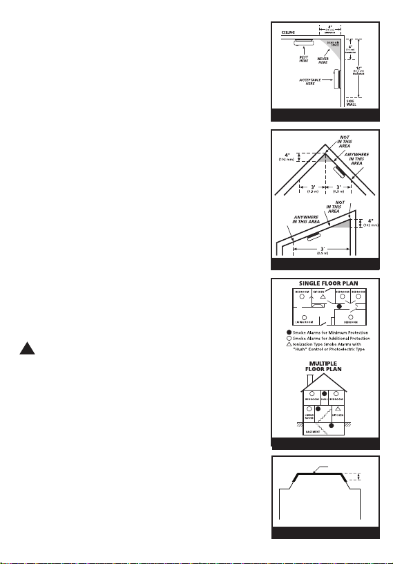
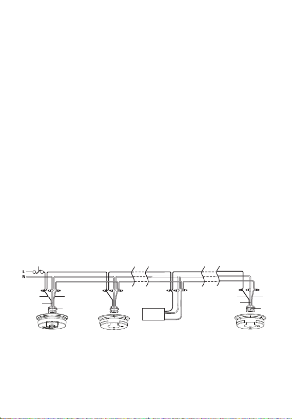
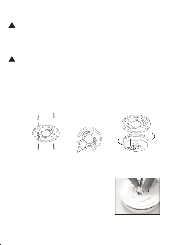
Kidde i4618AC User manual

P/N: 1261-7205-00
SIGNALING
LISTED
UL
ATTENTION: Please take a few minutes to thoroughly read
this user guide which should be saved for future reference and
passed on to any subsequent owner.
S oke Alar
User Guide
• 120 Volt Smoke Alarm with 9 Volt Battery Back-up
• Front Loa Battery
• Test an Hush®Button
i461 AC, i471 AC, i5000AC Series
Mo el: i4618AC
!
1261-7205-00_V3.qxd:_ 2016.7.29 2:43 PM Page 1

Smoke Alarm Procedure
NEVER IGNORE THE SOUND OF THE ALARM!
Smoke alarms are esigne to minimize false alarms. Cigarette
smoke will not normally set off the alarm, unless the smoke is
blown irectly into the alarm. Combustion particles from cook-
ing may set off the alarm if it is locate too close to the cook-
ing area. Large quantities of combustion particles are generat-
e from spills or when broiling. Using the fan on a range hoo
which vents to the outsi e (non-recirculating type) will also
help remove these combustion particles from the kitchen.
If the alarm soun s, check for fires first. If a fire is iscovere ,
follow these steps. Become thoroughly familiar with these
steps an review with all family members:
• Alert small chil ren in the home.
• Leave imme iately by your escape plan. Every secon
counts, so on’t waste time getting resse or picking up
valuables.
• In leaving, on’t open any insi e oor without first feeling its
surface. If hot, or if you see smoke seeping through cracks,
on’t open that oor! Instea , use your alternate exit. If the
insi e of the oor is cool, place your shoul er against it,
open it slightly an be rea y to slam it shut if heat an
smoke rush in.
• If the air is smoky, stay close to the floor. Breathe shallowly
through a cloth, wet if possible.
• Once outsi e, go to your selecte meeting place an make
sure everyone is there.
• Call the fire epartment from your cell phone outsi e or
neighbor’s home - not from yours!
• Don’t return to your home until the fire officials say that it is
all right to o so.
What to do When the Alarm Sounds!
1261-7205-00_V3.qxd:_ 2016.7.29 2:43 PM Page 2

A.C. Wire-in Single and/or Multiple Station (up to 24 Devices) Ionization
Smoke Alarm with 9 Volt Battery Back Up and HUSHTM Control to temporar-
ily silence nuisance alarms.
Thank you for purchasing this smoke alarm. It is an important part of your family’s
home safety plan. You can trust this pro uct to provi e the highest quality safety
protection. We know you expect nothing less when the lives of your family are at
stake. Firex alarms an accessories CAN ONLY BE interconnecte with other Ki e
an FireX alarms an accessories as well as specifie bran s an mo els of
interconnect compatible alarms. Connection of Firex pro ucts to a non-specifie
manufacturer’s interconnect system, or connection with non-specifie equipment
from another manufacturer into an existing Firex system coul result in nuisance
alarming, failure to alarm, or amage to one or all of the evices in the
interconnect system. Refer to the User Gui e supplie with each Firex pro uct for
interconnect compatible mo els, bran s, an evices. Refer to the wiring
instructions in section 3 for NFPA initiating evice limits.
This alarm etects pro ucts of combustion using the ionization technique. It
contains 0.9 microcurie of Americium 241, a ra ioactive material (see Section 9).
Distribute un er U.S. NRC License No. 32-23858-01E. Manufacture in
compliance with U.S. NRC safety criteria in 10 CFR 32.27. The purchaser is
exempt from any regulatory requirements. Do not try to repair the smoke alarm
yourself. Refer to the instructions in Section 12 for service.
IMPORTANT! READ ALL INSTRUCTIONS BEFORE INSTALLATION AND KEEP
THIS USER GUIDE NEAR THE ALARM FOR FUTURE REFERENCE.
CONTENTS OF THIS USER GUIDE
1 -- RECOMMENDED LOCATIONS FOR SMOKE ALARMS
2 -- LOCATIONS TO AVOID
3 -- INSTALLATION INSTRUCTIONS
4 -- OPERATION AND TESTING
-- NUISANCE ALARMS
6 -- MAINTENANCE
7 -- LIMITATIONS OF SMOKE ALARMS
8 -- GOOD SAFETY HABITS
9 -- NRC INFORMATION
10 -- NFPA PROTECTION STANDARD 72
11 -- CALIFORNIA STATE FIRE MARSHAL REQUIRED INFORMATION
12 -- SERVICE AND WARRANTY
1261-7205-00_V3.qxd:_ 2016.7.29 2:43 PM Page 3

WARNING! REMOVAL OF THE SMOKE ALARM BATTERY AND DISCONNECTING or
LOSS OF A.C. POWER WILL RENDER THE SMOKE ALARM INOPERATIVE.
ELECTRICAL RATING: 120 VAC, 60HZ, 80mA maximum per alarm (maximum
80mA for originating unit with 24 evices interconnecte ).
1. RECOMMENDED LOCATIONS FOR ALARMS
• Locate the first alarm in the imme iate area of the be rooms. Try to monitor
the exit path as the be rooms are usually farthest from the exit. If more than
one sleeping area exists, locate a itional alarms in each sleeping area.
• Locate a itional alarms to monitor any stairway as stairways act like chim-
neys for smoke an heat.
• Locate at least one alarm on every floor level.
• Locate an alarm in every sleeping room.
• Locate an alarm in every room where electrical appliances are operate (i.e.
portable heaters or humi ifiers).
• Locate an alarm in every room where someone sleeps with the oor close .
The close oor may prevent an alarm not locate in that room from waking
the sleeper.
• Smoke, heat, an combustion pro ucts rise to the ceiling an sprea horizon-
tally. Mounting the smoke alarm on the ceiling in the center of the room
places it closest to all points in the room. Ceiling mounting is preferre in
or inary resi ential construction.
• For mobile home installation, select locations carefully to avoi thermal
barriers that may form at the ceiling. For more etails, see MOBILE HOME
INSTALLATION.
• When mounting an alarm on the ceiling, locate it at a minimum of 4” (10 cm)
from the si e wall (see FIGURE 1).
• When mounting the alarm on the wall, use an insi e wall with the top e ge
of the alarm at a minimum of 4” (10 cm) an a maximum of 12” (30.5 cm)
below the ceiling (see FIGURE 1).
• Put smoke alarms at both en s of a be room hallway or large room if the
hallway or room is more than 30 feet (9.1 m) long.
• Install Smoke Alarms on slope , peake or cathe ral ceilings at or within 3ft
(0.9m) of the highest point (measure horizontally). NFPA 72 states: “Smoke
alarms in rooms with ceiling slopes greater than 1 foot in 8 feet (.3m in 2.4
m) horizontally shall be locate on the high si e of the room.” NFPA 72
states: “A row of etectors shall be space an locate within 3 ft (0.9m) of
the peak of the ceiling measure horizontally” (see FIGURE 3).
!
1261-7205-00_V3.qxd:_ 2016.7.29 2:43 PM Page 4

• Install Smoke Alarms on tray-shape ceilings (coffere
ceilings) on the highest portion of the ceiling or on the
slope portion of the ceiling within 12” (305mm) verti-
cally own from the highest point (see figure 4).
MOBILE HOME INSTALLATION
Mo ern mobile homes have been esigne an built
to be energy efficient. Install smoke alarms as recom-
men e above (refer to RECOMMENDED LOCATIONS
an FIGURES 1 an 2).
In ol er mobile homes that are not well insulate com-
pare to present stan ar s, extreme heat or col can
be transferre from the outsi e to the insi e through
poorly insulate walls an roof. This may create a
thermal barrier which can prevent the smoke from
reaching an alarm mounte on the ceiling. In such
units, install the smoke alarm on an insi e wall with
the top e ge of the alarm at a minimum of 4” (10 cm)
an a maximum of 12” (30.5 cm) below the ceiling
(see FIGURE 1).
If you are not sure about the insulation in your mobile
home, or if you notice that the outer walls an ceiling
are either hot or col , install the alarm on an insi e
wall. For minimum protection, install at least one
alarm close to the be rooms. For a itional protec-
tion, see SINGLE FLOOR PLAN in FIGURE 2.
WARNING: TEST YOUR SMOKE ALARM OPER-
ATION AFTER MOBILE HOME VEHICLE HAS BEEN
IN STORAGE, BEFORE EACH TRIP AND AT LEAST
ONCE A WEEK DURING USE.
2. LOCATIONS TO AVOID
• In the garage. Pro ucts of combustion are present
when you start your automobile.
• Less than 4” (10cm) from the peak of an “A” frame
type ceiling.
• In an area where the temperature may fall below
40ºF (4.4˚C) or rise above 100ºF (37.8˚C) , such as
garages an unfinishe attics.
ANYWHERE ALONG
THIS BOLD SURFACE
12”
(300mm)
FIGURE 4
FIGURE 1
ANYWHERE ALONG
FIGURE 3
FIGURE 2
!
1261-7205-00_V3.qxd:_ 2016.7.29 2:43 PM Page 5

• In usty areas. Dust particles may cause nuisance alarm or failure to alarm.
• In very humi areas (greater than 95% R.H.). Moisture or steam can cause
nuisance alarms.
• In insect-infeste areas.
• Smoke alarms shoul not be installe within 3 ft (.9m) of the following: the
oor to a kitchen, the oor to a bathroom containing a tub or shower, force
air supply ucts use for heating or cooling, ceiling or whole house ventilating
fans, or other high air flow areas.
• Kitchens. Normal cooking may cause nuisance alarms. If a kitchen alarm is
esire , it shoul have an alarm silence feature or be a photoelectric type.
• Near fluorescent lights. Electronic “noise” may cause nuisance alarms.
• Smoke alarms are not to be use with etector guar s unless the combination
(alarm an guar ) has been evaluate an foun suitable for that purpose..
3. INSTALLATION INSTRUCTIONS
WIRING REQUIREMENTS
• This smoke alarm shoul be installe on a U.L. liste or recognize junction
box. All connections shoul be ma e by a qualifie electrician an all wiring
use shall be in accor ance with articles 210 an 300.3(B) of the U.S. National
Electrical Co e ANSI/NFPA 70, NFPA 72 an /or any other co es having juris ic-
tion in your area. The multiple station interconnect wiring to the alarms must
be run in the same raceway or cable as the AC power wiring. In a ition, the
resistance of the interconnect wiring shall be a maximum of 10 ohms.
• The appropriate power source is 120 Volt A.C. Single Phase supplie from a
non-switchable circuit which is not protecte by a groun fault interrupter.
•WARNING: This alarm cannot be operate from power erive from a square
wave, mo ifie square wave or mo ifie sine wave inverters. These types of
inverters are sometimes use to supply power to the structure in off gri
installations, such as solar or win erive power sources. These power
sources pro uce high peak voltages that will amage the alarm.
WIRING INSTRUCTIONS FOR A.C. QUICK CONNECT HARNESS
CAUTION! TURN OFF THE MAIN POWER TO THE CIRCUIT BEFORE
WIRING THE ALARM.
• For alarms that are use as single station, DO NOT CONNECT THE RED WIRE
TO ANYTHING. Leave the re wire insulating cap in place to make certain that
the re wire cannot contact any metal parts or the electrical box.
• When alarms are interconnecte , all interconnecte units must be powere
from a single circuit.
!
!
1261-7205-00_V3.qxd:_ 2016.7.29 2:43 PM Page 6

• A maximum of 24 Ki e an /or FireX evices may be interconnecte in a
multiple station arrangement. The interconnect system shoul not excee the
NFPA interconnect limit of 12 smoke alarms an /or 18 alarms total (smoke,
heat, carbon monoxi e, etc.). With 18 alarms interconnecte , it is still
possible to interconnect up to a total of 6 remote signaling evices an /or
relay mo ules.
• When mixing mo els which have battery backup (1275, 1276, 1285, i12040,
i12040A, i12060, i12060A, i12080, i12080A, i4618, i4618A, i4618AC,
i4718A, i4718AC, i5000A, i5000AC, PE120, P12040, Pi2000, Pi2010,
KN-COPE-I, KN-SM-FM-I, KN-COSM-IB, KN-COSM-IBA, HD135F, KN-COB-IC,
KN-COP-IC, i12010S, i12010SCO, RF-SM-ACDC) with mo els without battery
backup, (1235, i12020, i12020A, KN-COSM-I, SM120X, CO120X, SL177i,
SLED177i) be a vise that the mo els without battery backup will not respon
uring an AC power failure.
• For more information about compatible interconnect units an their
functionality in an interconnect system, visit our web site at: www.Ki e.com
• The maximum wire run istance between the first an last unit in an
interconnecte system is 1000 feet.
•NOTE: This alarm is not compatible with Ki e CO-relays an Strobes manu-
facture before Nov. 1, 2011.
• Figure 5 illustrates interconnection wiring. Improper connection will result in
amage to the alarm, failure to operate, or a shock hazar .
• Make certain alarms are wire to a continuous (non-switche ) power line.
NOTE: Use stan ar UL liste househol wire (as require by local co es) avail-
able at all electrical supply stores an most har ware stores.
FIGURE 5 INTERCONNECT WIRING DIAGRAM
WIRES ON ALARM HARNESS CONNECTED TO
Black Hot Si e of A.C. Line
White Neutral Si e of A.C. Line
Re Interconnect Lines (Re Wires) of Other
Units in the Multiple Station Set up
FUSE OR CIRCUIT BREAKER
REDBLACK
WHITE
CONNECTOR
First
Alarm
Additional
Alarm
Kidde
Relay Module
SM120X
Optional Accessory
BLACK
WHITE
RED
CONNECTOR
Additional
Alarm
1261-7205-00_V3.qxd:_ 2016.7.29 2:43 PM Page 7

BATTERY INSTALLATION
See MAINTENANCE (Section 6) for battery installation.
CAUTION! THIS UNIT WILL NOT FUNCTION WITHOUT A PROPERLY
INSTALLED BATTERY, AND IS EQUIPPED WITH A BATTERY LOCKOUT FEA-
TURE WHICH PREVENTS THE BATTERY DOOR FROM CLOSING IF A BAT-
TERY IS NOT INSTALLED CORRECTLY.
MOUNTING INSTRUCTIONS
CAUTION: THIS UNIT IS SEALED. THE COVER IS NOT REMOVABLE!
1. Remove the trim ring from the back of the alarm by hol ing the trim ring an
twisting the alarm counter-clockwise.
2. After selecting the proper smoke alarm location as escribe in Section 1 an
wiring the AC Quick Connector as escribe in the WIRING INSTRUCTIONS,
attach the trim ring to the electrical box (see Figure 6). To ensure aesthetic align-
ment of the alarm with the hallway or wall, the “A” line on the mounting
bracket must be parallel with the hallway when ceiling mounte , or horizontal
when wall mounte .
3. Pull the AC QUICK CONNECTOR through the center hole in the mounting
bracket an secure the bracket, making sure that the mounting screws are posi-
tione in the small en s of the keyholes before tightening the screws.
4. Plug the AC QUICK CONNECTOR into the back of
the alarm (see Figure 7), making sure that the locks
on the connector snap into place. Then push the
excess wire back into the electrical box through the
hole in the center of the mounting bracket.
5. Install the alarm on the mounting bracket an
rotate the alarm clockwise until the alarm ratchets
into place (this ratcheting function allows for aes-
thetic alignment).
When
mounting in
a hallway,
the “A” line
shoul be
parallel with
the hallway.
When wall mounting,
the “A” line shoul be
horizontal.
Alignment Marks
Remove
Install
AA
FIGURE 6
!
!
FIGURE 7
1261-7205-00_V3.qxd:_ 2016.7.29 2:43 PM Page 8

NOTE: The alarm will mount to the bracket in 4 positions (every 90 egrees).
When wall mounting, make sure the battery box is at the bottom of the unit.
(see Figure 5).
6. Pull the Battery Pull Tab completely out of the unit. This will automatically
connect the battery.
CAUTION: Due to the loudness ( 5 decibels) of the alarm, always
stand an arms length away from the unit when testing.
7. Turn on the AC power. The green Power On In icator shoul be lit when the
alarm is operating from AC power. Confirm unit operation by pressing the
Test/Hush button.
8. Test the unit to ensure proper operation by pressing the Test/Hush Button for
a minimum of 5 secon s. (All interconnecte , battery backe up, alarms shoul
respon ).
TAMPER RESIST FEATURES
Smoke Alarm Tamper Resist Feature
This alarm has a tamper resist feature, which helps prevent someone from
removing the unit from the mounting bracket. It can be very effective in pre-
venting smoke alarm tampering.
Activate the smoke alarm tamper resist feature by breaking off the four posts in
the square holes in the mounting bracket (see Figure 8A). When the posts are
broken off, the tamper resist tab on the base is allowe to engage the mounting
bracket. Rotate the alarm onto the mounting bracket until you hear the tamper
resist tab snap into place, locking the alarm on the mounting bracket. Using the
tamper resist feature will help eter chil ren an others from removing the
alarm from the bracket. NOTE: To remove the alarm when the tamper resist tab
is engage , press own on the tamper resist tab, an rotate the alarm off the
bracket (see Figure 8B).
FIGURE B
Locations
of Posts
AA
FIGURE A
!
1261-7205-00_V3.qxd:_ 2016.7.29 2:43 PM Page 9

4. OPERATION AND TESTING
OPERATION: The smoke alarm is operating once A.C. power is applie , a fresh
battery is installe an testing is complete. When the smoke alarm ionization
chamber senses pro ucts of combustion, the horn will soun a lou (85 b) tem-
poral alarm until the sensing chamber is cleare of smoke particles.
HUSHTMCONTROL: The “HUSH” feature has the capability of temporarily esen-
sitizing the alarm circuit for up to 8 minutes. This feature is to be use only
when a known alarm con ition, such as smoke from cooking, activates the
alarm. The smoke alarm is esensitize by pushing the “TEST/HUSH” button on
the smoke alarm cover. If the smoke is not too ense, the alarm will silence
imme iately. The re LED will illuminate for 1.5 secon s every 8-10 secon s
while in hush. This in icates that the alarm is in a temporarily esensitize
con ition. The smoke alarm will automatically reset after approximately 8 min-
utes an soun the alarm if particles of combustion are still present. The
“HUSH” feature can be use repeate ly until the air has been cleare of the
con ition causing the alarm. Pushing the Test/Hush button on the alarm will en
the hush perio .
This alarm has a low battery HUSH feature. If the alarm is soun ing a low bat-
tery warning chirp, you can silence this chirp for approximately 13 hours by
pressing the Test/Hush button.
NOTE: DENSE SMOKE WILL OVERRIDE THE HUSH CONTROL FEATURE AND
SOUND A CONTINUOUS ALARM.
CAUTION: BEFORE USING THE ALARM HUSH FEATURE, IDENTIFY THE
SOURCE OF THE SMOKE AND BE CERTAIN A SAFE CONDITION EXISTS.
LED INDICATORS: This smoke alarm is equippe with re an green LED in ica-
tors. The green LED (when illuminate ) in icates the presence of AC power.
The re LED has four mo es of operation:
Standby Condition: The re LED will flash every 40 secon s to in icate
that the smoke alarm is operating properly.
Alarm Condition: When the alarm senses pro ucts of combustion an
goes into alarm, the re LED will flash one flash per
secon . The flashing LED an pulsating alarm will
continue until the air is cleare .
WHEN UNITS ARE INTERCONNECTED, only the re LED
of the alarm which senses the smoke or is being teste
(the originating unit) will flash. All other units in the
interconnect system will soun an alarm but their re
LED’s will NOT be flashing.
!
1261-7205-00_V3.qxd:_ 2016.7.29 2:43 PM Page 10

Alarm Memory: This smoke alarm is equippe with an alarm memory,
which provi es a visual in ication when an alarm has
been activate . The re LED will illuminate for about 1.5
secon s every 16-20 secon s to in icate the memory
con ition. The memory will remain activate until
pushing the Test/Hush Button resets it or will time-out
between 11 to 13 hours. In an interconnecte installation
only the memory of the originating alarm will be activate .
Hush®mode: The re LED will illuminate for 1.5 secon s every 8-10
secon s, in icating the smoke alarm is in the Hush®
mo e.
TESTING: Test by pushing the Test/Hush button on the cover an hol it own
for a minimum of 5 secon s. This will soun the alarm if all the electronic cir-
cuitry, horn an battery are working. In an interconnecte installation all inter-
connecte alarms shoul soun when the test feature on any one of the inter-
connecte alarms is activate . If no alarm soun s, check the fuse or circuit
breaker supplying power to the alarm circuit. If the alarm still oes not soun ,
the unit has efective batteries or other failure. DO NOT use an open flame to
test your alarm, you coul amage the alarm or ignite combustible materials
an start a structure fire.
TEST THE ALARM WEEKLY TO ENSURE PROPER OPERATION. Erratic or low soun
coming from your alarm may in icate a efective alarm, an it shoul be
returne for service (see Section 12).
5. NUISANCE ALARMS
Smoke alarms are esigne to minimize nuisance alarms. Cigarette smoke will
not normally set off the alarm, unless the smoke is blown irectly into the alarm.
Combustion particles from cooking may set off the alarm if the alarm is locate
close to the cooking area. Large quantities of combustible particles are generat-
e from spills or when broiling. Using the fan on a range hoo which vents to
the outsi e (non-recirculating type) will also help remove these combustible
pro ucts from the kitchen.
Mo el i4618AC has a “HUSH” feature that is extremely useful in a kitchen area
or other areas prone to nuisance alarms. For more information, refer to Section
4 OPERATION AND TESTING.
If the alarm oes soun , check for fires first. If a fire is iscovere , get out an
call the fire epartment. If no fire is present, check to see if one of the reasons
liste in Section 2 may have cause the alarm.
1261-7205-00_V3.qxd:_ 2016.7.29 2:43 PM Page 11

6. MAINTENANCE / TROUBLESHOOTING
ALARM REMOVAL
IF SMOKE ALARM TAMPER RESIST FEATURE HAS BEEN ACTIVATED, REFER
TO SMOKE ALARM TAMPER RESIST FEATURE IN SECTION 3 FOR REMOVAL
INSTRUCTIONS.
To remove the alarm from the trim ring, rotate the alarm counter clockwise in the
irection of the "OFF" arrow on the cover. To isconnect the A.C. power harness,
squeeze the locking arms on the si es of the Quick Connector while pulling the
connector away from the bottom of the alarm (see Section 3, Figure 7).
BATTERY INSTALLATION AND REMOVAL
To replace or install the battery sli e the battery oor in the irection in icate
on the cover of the alarm. The battery can then be pulle out of the carrier.
When installing a new battery into the carrier, make sure that the polarity
matches the markings printe on the insi e of the battery compartment.
Completely sli e the battery oor to the close position.
A missing or improperly installe battery will prevent the battery oor from clos-
ing an result in improper alarm operation.
This smoke alarm uses a 9V carbon zinc battery (alkaline batteries may also be
use ). A fresh battery shoul last for one year un er normal operating con i-
tions.
This alarm has a low/missing battery monitor circuit which will cause the alarm
to “chirp” approximately every 30-40 secon s for a minimum of seven (7) ays
when the battery gets low.Replace the battery when this con ition occurs.
NOTE: Low/missing battery monitor circuit WILL cause the unit to chirp while
replacing the battery. This function will cease once the new battery has been
installe . To avoi this “chirp” the unit can be remove from the base an is-
connecte from the AC power when replacing the battery, but it is not necessary.
USE ONLY THE FOLLOWING 9 VOLT BATTERIES FOR SMOKE ALARM
SLIDE OPEN INSERT
1261-7205-00_V3.qxd:_ 2016.7.29 2:43 PM Page 12

BATTERY REPLACEMENT.
Carbon-zinc type EVEREADY 1222; GOLD PEAK 1604P OR 1604S
GOLDEN POWER G6F22M
Alkaline type ENERGIZER 522; DURACELL MN1604 OR MX1604; GOLD
PEAK 1604A PANASONIC 6AM6, 6AM-6, 6AM-6PI,
6AM6X, AND 6LR61 (GA)
NOTE: Do not use lithium batteries in this unit.
These batteries can be purchased at your local retailer.
NOTE: WEEKLY TESTING IS REQUIRED!
WARNING! BE SURE TO FOLLOW BATTERY INSTALLATION INSTRUC-
TIONS PRINTED ON THE BACK OF THE ALARM AND USE ONLY THE BAT-
TERIES SPECIFIED. USE OF DIFFERENT BATTERIES MAY HAVE A DETRIMEN-
TAL EFFECT ON THE SMOKE ALARM.
WARNING: THIS ALARM WILL “CHIRP” IF ABNORMAL OPERATION OF
THE SMOKE-SENSING CHAMBER IS DETECTED. THIS CHIRP WILL OCCUR
APPROXIMATELY 20 SECONDS AFTER THE RED LED FLASH. REPLACE THE
ALARM IF THIS CONDITION OCCURS.
CLEANING YOUR ALARM
YOUR ALARM SHOULD BE CLEANED AT LEAST ONCE A YEAR
To clean your alarm, remove it from the mounting bracket as outline in the
beginning of this section. You can clean the interior of your alarm (sensing
chamber) by using compresse air or a vacuum cleaner hose an blowing or
vacuuming through the openings aroun the perimeter of the alarm. The out-
si e of the alarm can be wipe with a amp cloth. After cleaning, reinstall your
alarm, verify the green LED is on an test your alarm by using the Test/Hush
Button. If cleaning oes not restore the alarm to normal operation the alarm
shoul be replace .
7. LIMITATIONS OF SMOKE ALARMS
WARNING: PLEASE READ CAREFULLY AND THOROUGHLY
• NFPA 72 states: Life safety from fire in resi ential occupancies is base primari-
ly on early notification to occupants of the nee to escape, followe by the
appropriate egress actions by those occupants. Fire warning systems for
!
!
!
1261-7205-00_V3.qxd:_ 2016.7.29 2:43 PM Page 13

welling units are capable of protecting about half of the occupants in poten-
tially fatal fires. Victims are often intimate with the fire, too ol or young, or
physically or mentally impaire such that they cannot escape even when
warne early enough that escape shoul be possible. For these people, other
strategies such as protection-in-place or assiste escape or rescue are necessary.
• Lea ing authorities recommen that both ionization an photoelectric smoke
alarms be installe to help insure maximum etection of the various types of
fires that can occur within the home. Ionization sensing alarms may etect
invisible fire particles (associate with fast flaming fires) sooner than photo-
electric alarms. Photoelectric sensing alarms may etect visible fire particles
(associate with slow smol ering fires) sooner than ionization alarms.
•Abattery powere alarm must have a battery of the specifie type, in goo con-
ition an installe properly.
• A.C. powere alarms (without battery backup) will not operate if the A.C.
power has been cut off, such as by an electrical fire or an open fuse.
• Smoke alarms must be teste regularly to make sure the batteries an the
alarm circuits are in goo operating con ition.
• Smoke alarms cannot provi e an alarm if smoke oes not reach the alarm.
Therefore, smoke alarms may not sense fires starting in chimneys, walls, on
roofs, on the other si e of a close oor or on a ifferent floor.
• If the alarm is locate outsi e the be room or on a ifferent floor, it may not
wake up a soun sleeper.
• The use of alcohol or rugs may also impair one’s ability to hear the smoke
alarm. For maximum protection, a smoke alarm shoul be installe in each
sleeping area on every level of a home.
• Although smoke alarms can help save lives by provi ing an early warning of a
fire, they are not a substitute for an insurance policy. Home owners an
renters shoul have a equate insurance to protect their lives an property.
8. GOOD SAFETY HABITS
DEVELOP AND PRACTICE A PLAN OF ESCAPE
• Install an maintain Fire extinguishers on every level of the home an in the
kitchen, basement an garage. Know how to use a fire extinguisher prior to
an emergency.
• Make a floor plan in icating all oors an win ows an at least two (2)
escape routes from each room. Secon story win ows may nee a rope or
chain la er.
1261-7205-00_V3.qxd:_ 2016.7.29 2:43 PM Page 14
Table of contents
Other Kidde Smoke Alarm manuals

Kidde
Kidde DC-9102E-KID User manual

Kidde
Kidde I9030 User manual

Kidde
Kidde P3010K-CA User manual

Kidde
Kidde KN-COB-DP2 User manual

Kidde
Kidde WFP User manual

Kidde
Kidde KN-COSM-BCA User manual

Kidde
Kidde HART XL User manual

Kidde
Kidde i12060A User manual

Kidde
Kidde PI 2000 User manual

Kidde
Kidde Optica KC2-OS Assembly instructions

Kidde
Kidde PI9000 UK User manual

Kidde
Kidde P4010DCSCO-W User manual

Kidde
Kidde I240C User manual

Kidde
Kidde RF-SM-DC User manual

Kidde
Kidde I9040RV User manual

Kidde
Kidde PI9000 User manual

Kidde
Kidde 10SCO User manual

Kidde
Kidde 4899 User manual

Kidde
Kidde AirSense Stratos Micra 25 User manual

Kidde
Kidde i9040EU User manual