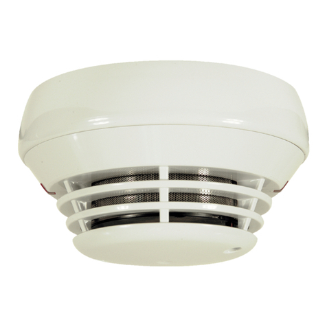
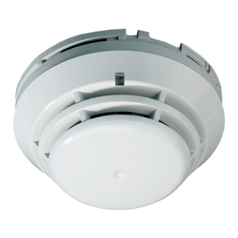
Kilsen KL710 Assembly instructions

KL710 and KL731 Conventional Point Detector
Installation Sheet
EN DE ES FR HU IT NL PL PT TR
1
2
3
4
5
6
© 2011 UTC Fire & Security. All rights reserved. 1 / 12 P/N 55370164 • REV 2.0 • ISS 16DEC11

EN: Installation Sheet
Installation
Caution: For general guidelines on system planning, design,
installation, commissioning, use, and maintenance, refer to the
EN 54-14 standard and local regulations.
To install a detector:
1. Insert the detector head into the mounting base and rotate
it clockwise until it clicks into place (Figure 1).
2. The detector may be locked into the mounting base if
required. To do this, remove the locking tab before
installation (Figure 2).
3. Always test detectors after installation.
To remove a locked detector:
1. Insert a small screwdriver into the locking tab slot
(Figure 3).
2. Press and rotate the detector anticlockwise.
Maintenance
Basic maintenance consists of a yearly inspection. Do not
modify internal wiring or circuitry.
To replace the optical chamber (KL731 and KL731B only):
1. Remove the detector head from the mounting base.
2. Remove the detector cover by pressing the catch with a
screwdriver, turning and lifting (Figure 4).
3. Remove the existing optical chamber and insert the
replacement optical chamber (Figures 5 and 6).
4. Replace the detector cover and install detector head into
the mounting base.
To clean the optical chamber, follow the above instructions for
removal and use compressed air to clear the dust.
Caution: The detector must be recalibrated after cleaning or
replacement of the optical chamber.
Specifications
KL710 KL731/KL731B
Operating voltage 18 to 28 VDC 9 to 28 VDC
Current
Standby
Alarm
70 µA
100 mA
85 µA
100 mA
Prealarm indication Flashing LED Flashing LED
Alarm indication Constant LED Constant LED
Coverage 60 to 80 m260 to 80 m2
IP rating IP42 IP42
Compatible mounting base KZ700, KZ705,
KZ705D
KZ700, KZ705,
KZ705D, KZ705R
Temperature
Operation
Storage
−10 to +60ºC
−10 to +70ºC
−10 to +60ºC
−10 to +70ºC
KL710 KL731/KL731B
Relative humidity 10 to 95%
noncondensing
10 to 95%
noncondensing
Colour White White/Black
Dimensions (Ø × H) 99 × 45 mm 99 × 45 mm
Weight 71 g 106 g
Regulatory information
KL710 KL731/KL731B
Description Heat detector Optical smoke
detector
Certification
CPD certificate 1134-CPD-007 1134-CPD-009
EN 54 EN 54-5 EN 54-7
EMC EN 50130-4
EN 61000-6-3
EN 50130-4
EN 61000-6-3
Manufacturer Shanghai UTC Fire & Security Electronics,
1st Floor No. 2 Building No. 211, Qinqiao
Road Jinqiao Export Processing Zone,
Pudong New Area 201206, Shanghai,
China
Authorized EU manufacturing
representative: UTC Fire & Security B.V.
Kelvinstraat 7, 6003 DH Weert,
Netherlands
Year of manufacture The year of manufacture is included in the
first two digits of your product serial number
(located on the product identification label)
2002/96/EC (WEEE directive): Products
marked with this symbol cannot be
disposed of as unsorted municipal waste in
the European Union. For proper recycling,
return this product to your local supplier
upon the purchase of equivalent new
equipment, or dispose of it at designated
collection points. For more information see:
www.recyclethis.info.
Contact information
For contact information, see www.utcfireandsecurity.com.
DE: Installationsanweisungen
Installation
Warnung: Allgemeine Richtlinien zu Planung, Projektierung,
Montage, Inbetriebsetzung, Betrieb und Instandhaltung finden
Sie in der Norm EN 54-14 und in den örtlich geltenden
Vorschriften.
Installation des Melder:
1. Setzen Sie den Melder in den Meldersockel und drehen
diesen im Uhrzeigersinn bis er einklickt. (Abbildung 1).
2. Der Melder kann verriegelt werden im Sockel, wenn
erforderlich. Entfernen Sie hierfür die Sperrvorrichtung
(Abbildung 2).
3. Test der Melder immer nach der Installation.
2 / 12 P/N 55370164 • REV 2.0 • ISS 16DEC11

Entfernen eines gesperrten Melder:
1. Einen kleinen Schraubendreher in die
Entriegelungsvorrichtung einsetzen (Abbildung 3).
2. Drücken und Drehen des Melder gegen den
Uhrzeigersinn.
Wartung
Grundlegend sollte einmal jährlich eine Wartung erfolgen. Die
interne Verdrahtung nicht verändern.
Austausch der Rauchkammer (nur KL731 und KL731B):
1. Entfernen des Melder aus dem Sockel.
2. Entfernen der Melderabdeckung durch seitliches Drücken
mit einem Schraubendreher, Drehen und Abheben
(Abbildung 4).
3. Entfernen der bestehenden Rauchkammer und Einsetzen
einer neuen Rauchkammer (Abbildung 5 und 6).
4. Montage der Melderabdeckung (Abbildung 6), und
Einsetzen des Melder in den Sockel.
Zur Reinigung der Rauchkammer folgen den obigen
Anweisungen als Austausch oder durch Reinigung mit
Pressluft zur Staubentfernung.
Achtung: Der Melder muss neu kalibriert werden nach der
Reinigung oder Austausch der Rauchmeßkammer.
Technische Daten
KL710 KL731/KL731B
Spannung 18 bis 28 VDC 9 bis 28 VDC
Stromentnahme
Ruhezustand
Alarm
70 µA
100 mA
85 µA
100 mA
Voralarm Anzeige Blinkende LED Blinkende LED
Alarm Anzeige Leuchtende LED Leuchtende LED
Überwachungsbereich 60 bis 80 m² 60 bis 80 m²
IP- Schutzklasse IP42 IP42
Passender Meldersockel KZ700, KZ705,
KZ705D
KZ700, KZ705,
KZ705D, KZ705R
Temperatur
Betrieb
Lagerung
−10 bis +60ºC
−10 bis +70ºC
−10 bis +60ºC
−10 bis +70ºC
Relative Luftfeuchtigkeit 10 bis 95% Relative
Luftfeuchtigkeit
10 bis 95% Relative
Luftfeuchtigkeit
Farbe Weiß Weiß/Black
Abmessungen (Ø × H) 99 × 45 mm 99 × 45 mm
Gewicht 71 g 106 g
Regulatorische Informationen
KL710 KL731/KL731B
Beschreibung Wärmemelder Optischer
Rauchmelder
Zertifikation
CPD Zertifikat Nummer 1134-CPD-007 1134-CPD-009
EN 54 EN 54-5 EN 54-7
KL710 KL731/KL731B
EMC EN 50130-4
EN 61000-6-3
EN 50130-4
EN 61000-6-3
Hersteller Shanghai UTC Fire & Security Electronics,
1st Floor No. 2 Building No. 211, Qinqiao
Road Jinqiao Export Processing Zone,
Pudong New Area 201206, Shanghai,
China
Autorisierter EU-Produktionsvertreter:
UTC Fire & Security B.V.
Kelvinstraat 7, 6003 DH Weert,
Netherlands
Herstellungsjahr Das Jahr der Herstellung ist in den beiden
ersten Ziffern der Produkt-Seriennummer
enthalten (auf dem Produkt-
Identifizierungslabel)
2002/96/EG (EEAG-Richtlinie): Innerhalb
der Europäischen Union dürfen mit dem
EEAG-Logo gekennzeichnete Produkte
nicht als unsortierter Hausmüll entsorgt
werden. Um eine ordnungsgemäße
Wiederverwertung zu gewährleisten,
können Sie Produkte, die mit diesem
Symbol versehen sind, beim Kauf eines
gleichartigen neuen Produktes zu Ihrem
Händler vor Ort bringen oder diese an den
geeigneten Sammelstellen entsorgen.
Weitere Informationen finden Sie unter:
www.recyclethis.info.
Kontaktinformationen
Kontaktinformationen finden Sie auf unserer Website:
www.utcfireandsecurity.com.
ES: Instrucciónes de instalación
Instalación
Precaución: Para información sobre el diseño, instalación,
uso y mantenimiento del sistema, aconsejamos seguir la
norma EN 54-14 y normas locales.
Para instalar el detector:
1. Insertar el detector en la base y girar en sentido horario
hasta que encaje perfectamente (Figura 1).
2. El detector se puede bloquear en la base en caso de ser
necesario. Para ello, quitar la lengüeta antes de su
instalación (Figura 2).
3. Siempre realizar un test después de la instalación.
Para quitar un detector bloqueado:
1. Insertar un pequeño destornillador en el orificio (ver
Figura 3).
2. Presionar y girar el detector en sentido anti-horario.
P/N 55370164 • REV 2.0 • ISS 16DEC11 3 / 12

Mantenimiento
El mantenimiento del dispositivo consistirá en una inspección
tanto visual como de funcionamiento a realizar anualmente. No
deberá manipularse el interior del dispositivo.
Para reemplazar la cámara óptica (KL731 y KL731B sólo):
1. Quitar la cabeza del detector de la base (Figura 3).
2. Quitar la cobertura del detector presionando con un
destornillador, girando y levantando (Figura 4).
3. Quitar la cámara óptica y colocar la cámara de reposición
(Figura 5 y 6).
4. Reemplazar la cobertura del detector y colocar la cabeza
del detector en la base.
Para limpiar la cámara óptica seguir las instrucciones
indicadas para su extracción y usar aire comprimido para la
limpieza del polvo.
Precaución: El detector debe ser recalibrado después de su
limpieza o sustitución de la cámara óptica.
Especificaciones técnicas
KL710 KL731/KL731B
Tensión de alimentación 18 a 28 VDC 9 a 28 VDC
Corriente de consumo
Normal
Alarma
70 µA
100 mA
85 µA
100 mA
Indicación de pre-alarma LED parpadeando LED parpadeando
Indicación de alarma LED constante LED constante
Cobertura 60 a 80 m260 a 80 m2
IP rating IP42 IP42
Bases compatibles KZ700, KZ705,
KZ705D
KZ700, KZ705,
KZ705D, KZ705R
Temperatura
Funcionamiento
Almacenaje
−10 a +60ºC
−10 a +70ºC
−10 a +60ºC
−10 a +70ºC
Humedad relativa 10 a 95%
(sin condensación)
10 a 95%
(sin condensación)
Color Blanco Blanco/Negro
Dimensiones (Ø × H) 99 × 45 mm 99 × 45 mm
Peso 71 g 106 g
Información regulatoria
KL710 KL731/KL731B
Descripción Detector térmico Detector óptico
Certificación
Número de certificado
CPD
1134-CPD-007 1134-CPD-009
EN 54 EN 54-5 EN 54-7
EMC EN 50130-4
EN 61000-6-3
EN 50130-4
EN 61000-6-3
KL710 KL731/KL731B
Fabricante Shanghai UTC Fire & Security Electronics,
1st Floor No. 2 Building No. 211, Qinqiao
Road Jinqiao Export Processing Zone,
Pudong New Area 201206, Shanghai,
China
Representante de fabricación autorizado
en Europa: UTC Fire & Security B.V.
Kelvinstraat 7, 6003 DH Weert,
Netherlands
Año de fabricación El año de la fabricación está indicado en
los dos primeros dígitos del número de
serie del producto (situado en la etiqueta
del producto)
2002/96/CE (directiva WEEE): aquellos
productos que tengan este símbolo no
podrán desecharse como residuos
municipales no clasificados en lo que
respecta al ámbito de la Unión Europea. Al
comprar un equipo nuevo equivalente,
devuelva este producto a su proveedor
local o deséchelo en los puntos de
recogida designados a tal efecto a fin de
ayudar a un proceso de reciclaje
adecuado. Para más información consulte:
www.recyclethis.info.
Información de contacto
Para obtener información de contacto, consulte nuestro sitio
Web: www.utcfireandsecurity.com.
FR: Instructions d'installations
Installation
Attention: Suivant les directives générales pour l’installation,
la mise en service et la maintenance, référez vous à la
directive EN 54-14.
Pour installer le détecteur:
1. Insérer la tête du détecteur dans le montage de base et le
faire pivoter vers la droite jusqu'à sa fixation (Figure 1).
2. Le détecteur doit être verrouillé dans de base si
nécessaire. Pour ce faire supprimer l'onglet de
verrouillage avant l'installation (Figure 2).
3. Effectuer toujours un essai après l'installation du
détecteur.
Pour supprimer un détecteur:
1. Insérez un petit tournevis dans la fente de verrouillage
onglet (Figure 3).
2. Presser et faites pivoter le détecteur dans le sens anti-
horlogique.
Maintenance
La maintenance de base se limite à une inspection annuelle.
Ne pas modifier le câblage interne.
4 / 12 P/N 55370164 • REV 2.0 • ISS 16DEC11

Pour remplacer la chambre optique (KL731 et KL731B
seulement):
1. Retirez le détecteur de tête du montage de base.
2. Retirez le détecteur en appuyant avec un tournevis, en
tournant et en levant (figure 4).
3. Retirez la chambre optiques existantes et insérer l'optique
de remplacement de chambre (figure 5/6).
4. Remplacer le couvercle du détecteur et installer le
détecteur dans le montage de base.
Pour nettoyer la chambre optique suivre les instructions ci-
dessus pour l'enlèvement et l'utiliser de l'air comprimé pour
éliminer la poussière.
Attention: Le détecteur doit être recalibré après le nettoyage
ou le remplacement de la chambre optique.
Caractéristiques techniques
KL710 KL731/KL731B
Tension 18 à 28 VDC 9 à 28 VDC
Courrant:
Repose
Alarme
70 µA
100 mA
85 µA
100 mA
Indication de pré-alarme LED clignotante LED clignotante
Indication d’alarme LED constante LED constante
Couverture 60 à 80 m260 á 80 m2
IP IP42 IP42
Base du détecteur KZ700, KZ705,
KZ705D
KZ700, KZ705,
KZ705D, KZ705R
Température:
Utilisation
Stockage
−10 à +60ºC
−10 à +70ºC
−10 à +60ºC
−10 à +70ºC
Humidité relative (sans
condensation)
10 à 95% 10 à 95%
Coulour Blanc Blanc/Noir
Dimensions (Ø × H) 99 × 45 mm 99 × 45 mm
Poids 71 g 106 g
Informations sur la réglementation
KL710 KL731/KL731B
Description Détecteur de
chaleur
Détecteur optique
Certification
Numéro du certificat
CPD
1134-CPD-007 1134-CPD-009
EN 54 EN 54-5 EN 54-7
EMC EN 50130-4
EN 61000-6-3
EN 50130-4
EN 61000-6-3
KL710 KL731/KL731B
Fabricant Shanghai UTC Fire & Security Electronics,
1st Floor No. 2 Building No. 211, Qinqiao
Road Jinqiao Export Processing Zone,
Pudong New Area 201206, Shanghai,
China
Représentant légal, européen, du fabricant:
UTC Fire & Security B.V.
Kelvinstraat 7, 6003 DH Weert,
Netherlands
Année de fabrication L’année de fabrication est inclue dans les
deux chiffres premiers du numéro de serié
du produit, qui ce trouve sur l’étiquette du
produit
2002/96/CE (directive DEEE) : Les produits
portant ce symbole ne peuvent pas être
mis au rebut avec les déchets municipaux
non assujettis au tri sélectif au sein de
l'Union européenne. Le remettre au
fournisseur local au moment de l'achat d'un
nouvel équipement équivalent ou le
déposer auprès d'un point de collecte
approprié. Pour plus d'informations,
consulter le site suivant :
www.recyclethis.info.
Pour nous contacter
Pour plus d'informations consulter notre site à l'adresse
www.utcfireandsecurity.com.
HU: Telepítési útmutató
Termék leírás
Figyelmeztetés: a rendszer tervezésekor, a kivitelezés
közben valamint az üzembe helyezés alatt és karbantartás
esetén is figyelembe kell venni az EN 54-14, illetve a helyi
szabályozásokat.
Az érzékelőtelepítése:
1. Helyezze az érzékelőt az aljzatba, majd fordítsa el az
óramutató járásával megegyezőirányba, amíg a helyére
nem pattan. (1. ábra).
2. Szükség esetén az érzékelőaz aljzatba zárolható. Ehhez
a telepítés előtt távolítsa el zároló mechanikát. (2. ábra).
3. Telepítés után minden esetben tesztelje az érzékelőt.
Zárolt érzékelőkiszedése:
1. Helyezzen egy csavarhúzót a zároló mechanika nyílásába
(3. ábra).
2. Nyomja meg, majd tekerje az érzékelőt az óramutató
járásával ellentétes irányba.
Karbantartás
Alap esetben a karbantartást évente szükséges megtenni. Ne
módosítson semmit a nyomtatott áramkörön.
P/N 55370164 • REV 2.0 • ISS 16DEC11 5 / 12

Az optikai kamra cseréje (csak a KL731 és KL731B
esetében):
1. Vegye ki az érzékelőt az aljzatból.
2. Vegye le az érzékelőfedelét a 4. ábrán látható módon.
3. Vegye ki a régi, majd tegye a helyére az új optikai kamrát
(5/6. ábra).
4. Tegye vissza az érzékelőfedelét, majd tekerje vissza az
érzékelőt az aljzatba.
Az optikai kamra megtisztításához kövesse a fenti utasítást,
majd sűrített levegőspray-vel tisztítsa meg a kamrát.
Figyelmeztetés: az optikai kamra cseréje vagy tisztítása után
kalibrálás szükséges.
Műszaki adatok
KL710 KL731/KL731B
Tápfeszültség 18 - 28 VDC 9 - 28 VDC
Áramfelvétel
nyugalmi
riasztási
70 µA
100 mA
85 µA
100 mA
Előriasztás jelzés Villogó LED Villogó LED
Riasztás jelzés Folyamatos LED Folyamatos LED
Védhetőterület 60 -80 m260 -80 m2
IP védettség IP42 IP42
Érzékelőaljzat KZ700, KZ705,
KZ705D
KZ700, KZ705,
KZ705D, KZ705R
Hőmérséklet tartomány
üzemi
tárolási
−10 - +60ºC
−10 - +70ºC
−10 - +60ºC
−10 - +70ºC
Relatív páratartalom 10 - 95% nem
lecsapódó
10 - 95% nem
lecsapódó
Szín Fehér Fehér/fekete
Méretek (Ø × H) 99 × 45 mm 99 × 45 mm
Súly 71 g 106 g
Gyártói információk
KL710 KL731/KL731B
Megnevezés HőérzékelőOptikai füstérzékelő
Tanúsítvány
CPD tanúsítvány 1134-CPD-007 1134-CPD-009
EN 54 EN 54-5 EN 54-7
EMC EN 50130-4
EN 61000-6-3
EN 50130-4
EN 61000-6-3
Gyártó Shanghai UTC Fire & Security Electronics,
1st Floor No. 2 Building No. 211, Qinqiao
Road Jinqiao Export Processing Zone,
Pudong New Area 201206, Shanghai,
China
Európai hivatalos gyártási képviselő:
UTC Fire & Security B.V.
Kelvinstraat 7, 6003 DH Weert,
Netherlands
Gyártási év A gyártási év a sorozatszám elsőkét
karakterében megtalálható (a termék
azonosító cimke)
KL710 KL731/KL731B
2002/96/EC (WEEE irányelv): Az ezzel a
szimbólummal megjelölt termékek az
Európai Unióban nem lehet szelektálatlan
háztartási hulladékként kidobni. A
megfelelőújrahasznosítás érdekében
juttassa vissza ezt a terméket a helyi
értékesítőhöz az új berendezés vásárlása
során, vagy egy erre kijelölt helyen dobja
ki. További információkért lásd:
www.recyclethis.info.
Elérhetőség
Az elérhetőségekért keresse fel honlapunkat:
www.utcfireandsecurity.com.
IT: Istruzioni di installazione
Installazione
Attenzione: per indicazioni di carattere generale inerenti la
configurazione del sistema, il progetto, l’installazione, la messa
in funzione, l’utilizzo e la manutenzione riferirsi alla direttiva
standard EN 54-14 e alle normative locali.
Installare il rivelatore:
1. Inserire il rivelatore nella base di montaggio e ruotarlo fino
a quando non scatta (Figura 1).
2. Il rivelatore può essere bloccato nella base di montaggio,
se richiesto. Per attivare il blocco, rimuovere la linguetta
prima dell’installazione del rivelatore (Figura 2).
3. Provare sempre i rivelatori dopo l’installazione.
Rimuovere un rivelatore bloccato:
1. Inserire un piccolo cacciavite nella fessura presente nella
base (Figura 3).
2. Premere e ruotare il rivelatore in senso antiorario.
Manutenzione
La manutenzione richiesta è stata ridotta ad una ispezione
all’anno. Non modificare i collegamenti interni o la circuiteria.
Cambiare la camera ottica (solo per modelli KL731
e KL731B):
1. Rimuovere il rivelatore dalla base di montaggio.
2. Rimuovere la calotta del rivelatore premendo con un
cacciavite il fermo, ruotare e tirare verso l’esterno (Figura
4).
3. Rimuovere la camera ottica ed inserire la camera ottica di
ricambio (Figura 5 e 6).
4. Riposizionare la calotta del rivelatore, ed installare il
rivelatore nella base di montaggio.
Per pulire la camera ottica seguire le precedenti istruzioni per
la rimozione e utilizzare aria compressa per togliere la polvere.
6 / 12 P/N 55370164 • REV 2.0 • ISS 16DEC11

Attenzione: Il rivelatore deve essere ricalibrato dopo la
pulizzia o la sostituzione della camera ottica.
Specifiche tecniche
KL710 KL731/KL731B
Alimentazione Da 18 a 28 Vcc Da 9 a 28 Vcc
Assorbimento
Riposo
Allarme
70 µA
100 mA
85 µA
100 mA
Indicazione preallarme LED lampeggianti LED lampeggianti
Indicazione allarme LED accesi LED accesi
Copertura Da 60 a 80 m2Da 60 a 80 m²
Grado di protezione IP42 IP42
Basi KZ700, KZ705,
KZ705D
KZ700, KZ705,
KZ705D, KZ705R
Temperatura:
di lavoro
di stoccaggio
Da −10 a +60ºC
Da −10 a +70ºC
Da −10 a +60ºC
Da −10 a +70ºC
Umidità relative Da 10 a 95% senza
condensa
Da 10 a 95% senza
condensa
Colore Bianco Bianco/Nero
Dimensioni (Ø × H) 99 × 45 mm 99 × 45 mm
Peso 71 g 106 g
Informazioni sulle normative
KL710 KL731/KL731B
Descrizione Rivelatore
termovelocimetrico
Rivelatore ottico di
fumo
Certificazione
CPD Certificato numero 1134-CPD-007 1134-CPD-009
EN 54 EN 54-5 EN 54-7
EMC EN 50130-4
EN 61000-6-3
EN 50130-4
EN 61000-6-3
Fabbricante Shanghai UTC Fire & Security Electronics,
1st Floor No. 2 Building No. 211, Qinqiao
Road Jinqiao Export Processing Zone,
Pudong New Area 201206, Shanghai,
China
Rappresentante di produzione autorizzato
per l'UE: UTC Fire & Security B.V.
Kelvinstraat 7, 6003 DH Weert,
Netherlands
Anno di produzione Per conoscere l'anno di produzione del
prodotto verificare le prime due cifre del
numero di serie del prodotto stesso.
Riferirsi all'etichetta di identificazione
prodotto
2002/96/CE (Direttiva WEEE): I prodotti
contrassegnati da questo simbolo,
all'interno dell'Unione europea non
possono essere smaltiti come rifiuti
domestici indifferenziati. Ai fini di un
adeguato riciclaggio, al momento
dell'acquisto di un'apparecchiatura nuova
analoga restituire il prodotto al fornitore
locale o smaltirlo consegnandolo presso gli
appositi punti di raccolta. Per ulteriori
informazioni vedere: www.recyclethis.info.
Informazioni di contatto
Le informazioni di contatto sono disponibili sul sito web
www.utcfireandsecurity.com.
NL: Installatie instructies
Installatie
Let Op: Voor algemene voorschriften voor systeem planning,
ontwerp, installatie, in bedrijf stellen, gebruik en onderhoud,
verwijzen we naar de EN 54-14 standaards and lokale
regelgeving.
Een detector installeren:
1. Druk de detector in de montagevoet en draai hem met de
klok mee totdat men een klik hoort (Figuur 1).
2. De detector kan worden geblokkeerd in de montagevoet
indien nodig. Om dit te doen verwijder het
blokkeermechanisme voor de installatie (Figuur 2).
3. Test een detector altijd na installatie.
Het verwijderen van een geblokkeerde detector:
1. Steek een smalle schroevendraaier in het gaatje aan de
zijkant van de detector (Figuur 3).
2. Druk en draai de detector tegen de klok in.
Onderhoud
Basis onderhoud is verminderd tot een jaarlijkse inspectie.
Wijzig geen interne bedrading of circuits.
Verwisselen van de optische kamer (KL731 en KL731B):
1. Verwijder de detector van de montagevoet.
2. Verwijder de kap van de detector door het drukken van
een schroevedraaier op de kap, draaien en trekken
(Figuur 4).
3. Verwijder de optische kamer en vervang deze door een
nieuwe (Figuur 5/6).
4. Zet de kap terug op de detector, en installeer de detector
in de montagevoet.
Voor het reinigen van de optische kamer volg de
bovenstaande instructies voor het verwijderen en gebruik een
compressor om deze door te blazen.
Waarschuwing: De optische detector moet altijd opnieuw
worden gekalibreerd na het vervangen van de optische kamer.
Technische specificaties
KL710 KL731/KL731B
Spanning 18 tot 28 VDC 9 tot 28 VDC
Stroomverbruik
Rust
Alarm
70 µA
100 mA
85 µA
100 mA
Voor-alarm indicatie Knipperende LED Knipperende LED
P/N 55370164 • REV 2.0 • ISS 16DEC11 7 / 12

KL710 KL731/KL731B
Alarm indicatie Constante LED Constante LED
Bereik 60 tot 80 m260 tot 80 m2
IP klasse IP42 IP42
Bijbehorende montagevoet KZ700, KZ705,
KZ705D
KZ700, KZ705,
KZ705D, KZ705R
Temperatuur
In bedrijf
Opgeslagen
−10 tot +60ºC
−10 tot +70ºC
−10 tot +60ºC
−10 tot +70ºC
Relatieve vochtigheid
(geen condensatie)
10 tot 95% 10 tot 95%
Kleur Wit Wit/Zwart
Afmetingen (Ø × H) 99 × 45 mm 99 × 45 mm
Gewicht 71 g 106 g
Van toepassing zijnde normen
KL710 KL731/KL731B
Omschrijving Thermische detector Optische detector
Certificatie
CPD certificatie nummer 1134-CPD-007 1134-CPD-009
EN 54 EN 54-5 EN 54-7
EMC EN 50130-4
EN 61000-6-3
EN 50130-4
EN 61000-6-3
Fabrikant Shanghai UTC Fire & Security Electronics,
1st Floor No. 2 Building No. 211, Qinqiao
Road Jinqiao Export Processing Zone,
Pudong New Area 201206, Shanghai,
China
EU-geautoriseerde vertegenwoordiger
autorizzato per l'UE:
UTC Fire & Security B.V.
Kelvinstraat 7, 6003 DH Weert,
Netherlands
Productiejaar Het productiejaar wordt vermeld door de
eerste twee getallen in het serienummer
van het product (zichtbaar op de product
identificatie label)
2002/96/EC (WEEE-richtlijn): Producten
die van dit waarmerk zijn voorzien, mogen
in de Europese Unie niet bij het
ongesorteerde gemeenteafval worden
gegooid. U kunt dit product retourneren
aan uw plaatselijke leverancier op het
moment dat u vergelijkbare nieuwe
apparatuur aanschaft, of inleveren op een
aangewezen inzamelpunt voor de juiste
recycling. Meer informatie vindt u in:
www.recyclethis.info.
Contact informatie
Bezoek onze website voor contact informatie:
www.utcfireandsecurity.com.
PL: Instrukcje instalacji
Instalacja
Uwaga: Należy przestrzegaćlokalnych i ogólnych (EN 54-14)
przepisów dotyczących planowania, projektowania,
instalowania i konserwacji systemu.
Aby zainstalowaćczujkęnależy:
1. Włożyćgłowicęczujki do podstawy montażowej i
przekręcićzgodnie z ruchem wskazówek zegara, ażdo
zatrzaśnięcia (Rysunek 1).
2. Głowica czujki może zostaćzablokowana w podstawie
montażowej, jeśli zachodzi taka potrzeba. Aby tego
dokonać, należy przed instalacjąusunąć zawleczkę
blokującą(Rysunek 2).
3. Zawsze należy przetestowaćczujki po instalacji.
Aby wymontowaćzablokowanączujkęnależy:
1. Wsunąć końcówkęcienkiego wkrętaka w otwór zwolnienia
blokady (Rysunek 3).
2. Przytrzymując wkrętak wsunięty w otwór, należy obrócić
czujkęw kierunku przeciwnym do ruchu wskazówek
zegara.
Konserwacja
Konserwacja jest ograniczona do corocznych przeglądów. Nie
należy dokonywaćżadnych zmian w konstrukcji podstaw lub w
okablowaniu.
Aby wymienićkomoręoptyczną(tylko KL731 i KL731B)
należy:
1. Wyjąć głowicęczujki z podstawy montażowej.
2. Naciskając wkrętakiem zatrzask, jednocześnie obracając i
unosząc w gorę, zdjąć pokrywęczujki (Rysunek 4).
3. Wyjąć obecnąkomoręoptycznąi zastąpićjąnową
(Rysunek 5/6).
4. Założyćz powrotem pokrywęczujki, następnie
zainstalowaćczujkęw podstawie montażowej.
Aby oczyścićkomoręoptycznąnależy, postępując godnie z
powyższąinstrukcją, zdemontowaćczujkę. Następnie
używając sprężonego powietrza usunąć kurz z komory
optycznej.
Uwaga: Czujka musi byćponownie poddana procesowi
kalibracji po wymianie lub czyszczeniu komory optycznej.
Dane techniczne
KL710 KL731/KL731B
Napięcie zasilające Od 18 do 28 V DC Od 9 do 28 V DC
Prąd
Spoczynkowy
W alarmie
70 µA
100 mA
85 µA
100 mA
8 / 12 P/N 55370164 • REV 2.0 • ISS 16DEC11

KL710
KL731/KL731B
Sygnalizacja stanu
przedalarmowego
Migająca dioda LED Migająca dioda LED
Sygnalizacja stanu
alarmowego
Świecąca dioda
LED
Świecąca dioda
LED
Pokrycie 60 do 80 m2 60 do 80 m2
Klasa IP IP42 IP42
Kompatybilne podstawy
montażowe
KZ700, KZ705,
KZ705D
KZ700, KZ705,
KZ705D, KZ705R
Temperatura
Robocza
Przechowywania
−10 to +60ºC
−10 to +70ºC
−10 to +60ºC
−10 to +70ºC
Wilgotność względna 10 to 95% bez
kondensacji
10 to 95% bez
kondensacji
Kolor Biały Biały/Czarny
Wymiary (Ø × H) 99 × 45 mm 99 × 45 mm
Waga 71 g 106 g
Informacje prawne
KL710 KL731/KL731B
Opis Czujka temperatury Optyczna czujka
dymu
Certyfikat
Numer certyfikatu CPD 1134-CPD-007 1134-CPD-009
EN 54 EN 54-5 EN 54-7
EMC EN 50130-4
EN 61000-6-3
EN 50130-4
EN 61000-6-3
Wytwórca Shanghai UTC Fire & Security Electronics,
1st Floor No. 2 Building No. 211, Qinqiao
Road Jinqiao Export Processing Zone,
Pudong New Area 201206, Shanghai,
China
Autoryzowany przedstawiciel producenta
na terenie UE: UTC Fire & Security B.V.
Kelvinstraat 7, 6003 DH Weert,
Netherlands
Rok produkcji Rok produkcji reprezentujądwie pierwsze
cyfry numeru seryjnego produktu
(zlokalizowanego na etykiecie
identyfikacyjnej produktu)
2002/96/EC (dyrektywa WEEE): Na
obszarze Unii Europejskiej produktów
oznaczonych tym znakiem nie wolno
wyrzucaćwraz z odpadami miejskimi. W
celu zapewnienia prawidłowej utylizacji,
produkt należy oddaćlokalnemu
sprzedawcy lub przekazaćdo
wyznaczonego punktu zbiórki. Aby uzyskać
więcej informacji, zobacz:
www.recyclethis.info.
Informacje kontaktowe
Informacje kontaktowe sądostępne w naszej witrynie
internetowej: www.utcfireandsecurity.com.
PT: Instruções de instalação
Instalação
Advertência: Para informação geral sobre planeamento do
sistema, arquitectura, instalação, configuração, utilização e
manutenção, consulte a norma EN 54-14 ou a
regulamentações locais.
Para instalar o detector:
1. Insira do detector na base e rode no sentido dos ponteiros
do relógio, até fixar. (Figura 1).
2. O detector pode ser bloqueado na base se necessário.
Para bloquear, remova o ponto de bloqueio (Figura 2).
3. Teste sempre os detectores após instalação.
Para remover um detector bloqueado:
1. Insira uma chave de fendas pequena na ranhura
(Figura 3).
2. Pressione e rode o detector no sentido contrário aos
ponteiros do relógio.
Manutenção
A manutenção básica encontra-se reduzida a uma inspecção
anual. Não modificar as ligações ou circuitos internos.
Para substituir a câmara óptica (Somente KL731 e
KL731B):
1. Remova o detector da base.
2. Remova a cobertura do detector pressionando o ‘travão’
com uma chave de fendas, rode e levante (Figura 4).
3. Remova a câmara óptica e coloque uma nova (Figura 5
y 6).
4. Coloque a cobertura do detector, e coloque o detector na
base.
Para limpar a câmara óptica, remova-a conforme descrito e
utilize ar comprimido para limpar.
Cuidado: O detector tem de ser recalibrado após limpeza ou
substituição do bloco óptico.
Especificações técnicas
KL710 KL731/KL731B
Tensão 18 a 28 VDC 9 a 28 VDC
Consumo
Standby
Alarma
70 µA
100 mA
85 µA
100 mA
Indicação Pré-alarme LED a piscar LED a piscar
Indicação de alarme LED aceso LED aceso
Cobertura 60 a 80 m260 a 80 m2
Índice de protecção IP42 IP42
Base compatível KZ700, KZ705,
KZ705D
KZ700, KZ705,
KZ705D, KZ705R
P/N 55370164 • REV 2.0 • ISS 16DEC11 9 / 12

Temperatura
Operação
Armazenamento
−10 a +60ºC
−10 a +70ºC
−10 a +60ºC
−10 a +70ºC
Humidade relativa 10 a 95%
não condensado
10 a 95%
não condensado
Color Branco Branco/Preto
Dimensões (Ø × A) 99 × 45 mm 99 × 45 mm
Peso 71 g 106 g
Informação reguladora
KL710 KL731/KL731B
Descrição Detector térmico Detector óptico de
fumos
Certificação
Nº de certificado CPD 1134-CPD-007 1134-CPD-009
EN 54 EN 54-5 EN 54-7
EMC EN 50130-4
EN 61000-6-3
EN 50130-4
EN 61000-6-3
Fabricante Shanghai UTC Fire & Security Electronics,
1st Floor No. 2 Building No. 211, Qinqiao
Road Jinqiao Export Processing Zone,
Pudong New Area 201206, Shanghai,
China
Representante de fabrico autorizado na
UE: UTC Fire & Security B.V.
Kelvinstraat 7, 6003 DH Weert,
Netherlands
Ano de fabrico O ano de fabrico é indicado pelos primeiros
2 dígitos do número de série do
equipamento (localizado na etiqueta de
identificação do produto)
2002/96/CE (directiva WEEE, sobre
Resíduos de Equipamentos Eléctricos e
Electrónicos): Os produtos marcados com
este símbolo não podem ser eliminados
como lixo municipal não separado na
União Europeia. Para uma reciclagem
adequada, devolva este equipamento ao
fornecedor local aquando da compra de um
novo equipamento equivalente, ou
coloque-o num ponto de recolha designado
para o efeito. Para mais informações,
consulte: www.recyclethis.info.
Informação de contacto
Para informações de contacto, consulte o nosso Web site:
www.utcfireandsecurity.com.
TR: Montaj notları
Montaj
Uyarı: Genel sistem dizaynı, montaj , devreye alma , işletme
ve bakımıEN 54-14 standardıve yerel tüzükler gözönünde
bulundurularak yapılacaktır.
Dedektör montajı:
1. Dedektörü, tabanına oturtarak saat yönünde yerleşme sesi
gelene kadar çeviriniz. (Tablo 1)
2. İstenirse dedektör, tabanına kilitli kalacak pozisyonda
bırakılabilir. Bunu yapmak için dedektörü monte etmeden
once kilitleme etiketini çıkartınız. (Tablo 2)
3. Mutlaka dedektör montajıbittikten sonra doğruluğunu test
ediniz.
Tabanına kilitlenmişdedektörü sökmek için:
1. Kilitleme etiketine küçük bir tornavida sokunuz. (Tablo 3)
2. Etikete basarak dedektörü saat yönünün tersinde çeviriniz.
Bakım
Genel olarak bakım yıllık kontrollerde yapılabilir. Dahili
kablolamayılütfen hiçbir şekilde değiştirmeyiniz.
Optik muhafazanın değişimi (Sadece KL731 ve KL731B):
1. Dedektörü tabanından çıkarınız.
2. Dedektör kasasınıbir tornavida yardımıyla üzerindeki dile
basarak çıkarınız. (Tablo 4)
3. Mevcut muhafazayıçıkartarak yerine yenisini takınız.
(Tablo 5/6)
4. Dedektör kasasınıyeniden yerine takınız. ve dedektörü
tabanına takınız.
Dedektör temizliği için yukarıdaki notlarıdikkate alınız ve
üzerindeki tozu temizlemek için basınçlıhava kullanınız.
Uyarı: Dedektör temizlendikten ya da optik çemberin
değiştirilmesinden sonra yeniden kalibre edilmelidir.
Özellikler
KL710 KL731/KL731B
İşletme gerilimi 18 ile 28 VDC 9 ile 28 VDC
Akım
Sukunet
Alarm
70 µA
100 mA
85 µA
100 mA
Ön-alarm durumu Yanıp sönen LED Yanıp sönen LED
Alarm durumu Sürekli yanan LED Sürekli yanan LED
Etkili olduğu alan 60 ile 80 m260 ile 80 m2
IP değeri IP42 IP42
Uyumlu dedektör tabanıKZ700, KZ705,
KZ705D
KZ700, KZ705,
KZ705D, KZ705R
10 / 12 P/N 55370164 • REV 2.0 • ISS 16DEC11

KL710
KL731/KL731B
Sıcaklık
İşletme
Depolama
−10 ile +60ºC
−10 ile +70ºC
−10 ile +60ºC
−10 ile +70ºC
Gerçek nem 10 ile 95%
yoğuşmasız
10 ile 95%
yoğuşmasız
Renk Beyaz Beyaz/Siyah
Boyutlar (Ø × H) 99 × 45 mm 99 × 45 mm
Ağırlık 71 g 106 g
Düzenleyici bilgiler
KL710 KL731/KL731B
Açıklama Isıdedektörü Optik duman
dedektörü
Sertifikalar
CPD sertifikası1134-CPD-007 1134-CPD-009
EN 54 EN 54-5 EN 54-7
EMC EN 50130-4
EN 61000-6-3
EN 50130-4
EN 61000-6-3
Üretici Shanghai UTC Fire & Security Electronics,
1st Floor No. 2 Building No. 211, Qinqiao
Road Jinqiao Export Processing Zone,
Pudong New Area 201206, Shanghai,
China
Yetkili AB üretim temsilcisi:
UTC Fire & Security B.V.
Kelvinstraat 7, 6003 DH Weert,
Netherlands
Üretim yılıÜrünün üzerindeki seri numarasının ilk iki
basamağıüretim tarihini göstermektedir.
(Ürün etiketi üzerindeki numara)
2002/96/EC (WEEE direktifi): Bu sembol ile
işaretlenmişürünler Avrupa Birliğinde
sınıflandırılmamışevsel atık olarak
atılamazlar. Uygun geri dönüşüm için, denk
bir ürün satın almanızdan sonra bu ürünü
yerel tedarikçinize iade edin veya
belirlenmiştoplama noktalarına götürün.
Daha fazla bilgi için bkz:
www.recyclethis.info.
İletişim bilgisi
İletişim bilgisi için Web sitemize bakın:
www.utcfireandsecurity.com.
P/N 55370164 • REV 2.0 • ISS 16DEC11 11 / 12

12 / 12 P/N 55370164 • REV 2.0 • ISS 16DEC11
Other manuals for KL710
3
This manual suits for next models
1
Table of contents
Other Kilsen Security Sensor manuals
Popular Security Sensor manuals by other brands

Blocklychain
Blocklychain MD-104 manual

Fisher Labs
Fisher Labs XLT-30 operating manual

STEINEL PROFESSIONAL
STEINEL PROFESSIONAL True Presence COM1 Information

Huazheng
Huazheng HZ-5000 user manual

PCB Piezotronics
PCB Piezotronics W138A01/038CY250AC Installation and operating manual

Johnson Controls
Johnson Controls LC-203 quick start guide