manuals.online logo
Brands
  1. Home
  2. •
  3. Brands
  4. •
  5. Texecom
  6. •
  7. Security Sensor
  8. •
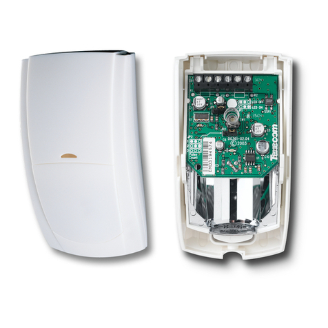
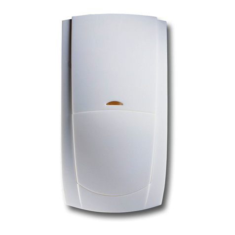
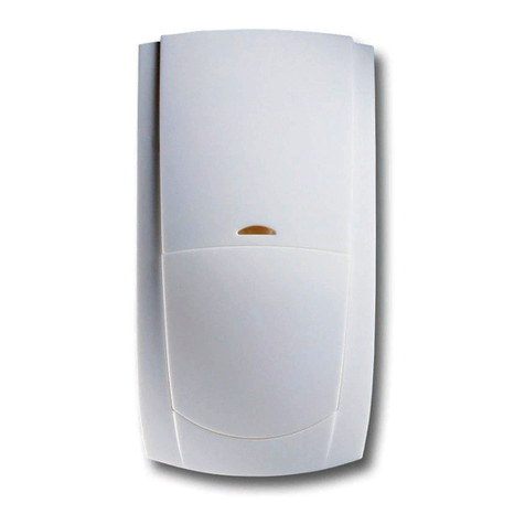
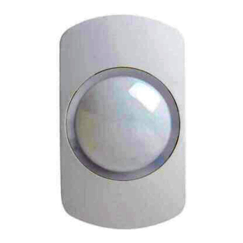
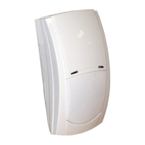
  9. Texecom Prestige DT User manual

Texecom Prestige DT User manual

WARRANTY
10 year replacement warranty.
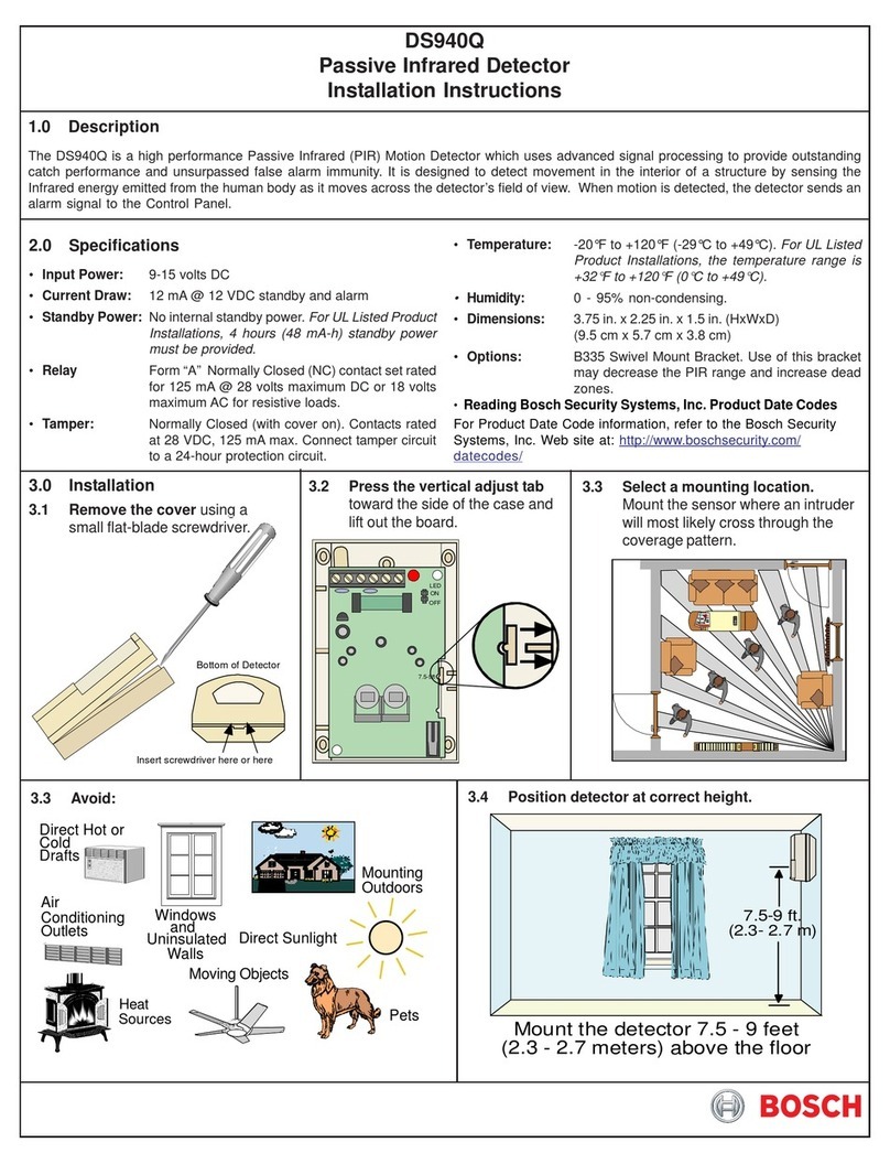
The Prestige DT is designed to detect the movement of an intruder and activate
an alarm control panel. As the Prestige DT is not a complete alarm
system, but only a part thereof, Texecom cannot accept responsibility or liability for
any damages whatsoever based on a claim that the Prestige DT failed to
function correctly.
Due to our policy of continuous improvement Texecom reserves the right to
change specification without prior notice. All specifications are measured at 68ºF
(20ºC).
© 2007 Texecom Ltd. The Prestige DT is protected by UK & International Registered Designs. Registered Design No’s:
3004997, 3004260 & 3004261. Prestige is a trademark of Texecom Ltd.
3 STANDARDS & APPROVALS
The latch terminal (see Section 5) can perform several different functions
depending on how it is connected:
Latch connected to Set Positive (SW+, Set+): The LEDs will be disabled while
the system is set. Any detectors triggered while the system is set will indicate
this by permanently lighting the alarm LED (upon unsetting the system).
Detectors can be reset by taking the latch line high and then low again.
Latch connected to Alarm Positive (AL+, A+ve): The first detector activated
while the system is set will indicate this with a slowly flashing alarm LED
(upon unsetting the system). Detectors activated subsequently will indicate
this by permanently lighting the alarm LED. Detectors can be reset by taking
the latch line high and then low again.
8 ALTERING COVERAGE AT 6'7"/2m
MOUNTING HEIGHT
6 ANGLING THE DETECTOR
2 ENVIRONMENTAL1 PHYSICAL
-31°F (-35°C) to +140°F (+60°C)
6oz (170g) approx.
-31°F (-35°C) to +135°F (+55°C)
2.4”
(60mm)
1.6”
(40mm)
4.4”
(112.25mm)
0.1”(2.5mm) ABS
Professional Dual Technology Detector
I N S T A L L A T I O N I N S T R U C T I O N S
INS 332
2
Ask your distributor today for the Texecom full colour Product Guide.
JP1
JP1
JP2
JP2
✗
LED ON
LED OFF
9’10”/3.0m
8’2”/2.5m
6’7”/2.0m
4’11”/1.5m
7 MOUNTING HEIGHT AND
SETTINGS
VR1
MIN
MID
MAX
5m
16'4"
2m
6
'
7
"
!
2m
6
'
7
"
15m
50'
2m
6
'
7
"
✗
DO NOT TOUCH
1
PULSE COUNT
5
4 LATCH INPUT FUNCTIONS ALARM PIRMW
This equipment may be operated
in the following countries:
10.525GHz: BEL, CYP, DNK, GRC, HUN, IRL,
ITA, LVA, LTU, LUX, MLT, NLD, POL, ROU, SVN, ESP, SWE, ISL, CAN, USA
www.texe.com
UL Standard: UL639 Intrusion Detection Unit.
EU Detector Standard: Independently Certified to TS 50131-2-4 Grade
2 Environmental Class II.
EU System Standard: Suitable for use in a PD 6662/BS EN 50131-1
Grade 2 system. Environmental Class II.
EMC: Independently Certified to EN 50130-4 : 1996.
A1 : 1998, A2 : 2003.
RF Immunity: No false alarms from 80MHz to 2GHz at 10V/m.
Complies with BS EN 61000-4-3 : 2002.
Electrostatic Discharge: No false alarms up to 8kV.
Complies with BS EN 61000-4-2 : 1995.
Fast Transient Immunity: No false alarms up to ±4kV.
Complies with BS EN 61000-4-4 : 1995.
High Energy Transient
Immunity:
No false alarms up to ±2kV.
Complies with BS EN 61000-4-5 : 1995.
Conducted RF
Susceptibility:
No false alarms at 10Vrms.
Complies with BS EN 61000-4-6 : 1996.
Conducted & Radiated
Emissions:
Complies with EN 55022 Class B.
EN 61000-6-3 : 2001, A11 : 2004
Product Identifier: DT.
Certificate Number: FM 35285
Made In England
FCC ID: MYJPRESTIGE-DT
NOTE:
This equipment has been tested and found to comply with the limits for a Class B digital
device, pursuant to Part 15 of the FCC Rules. These limits are designed to provide
reasonable protection against harmful interference in a residential installation. This
equipment generates, uses and can radiate radio frequency energy and, if not installed
and used in accordance with the instructions, may cause harmful interference to radio
communications. However, there is no guarantee that interference will not occur in a
particular installation. If this equipment does cause harmful interference to radio or
television reception, which can be determined by turning the equipment off and on,
the user is encouraged to try to correct the interference by one or more of the following
measures:
• Reorient or relocate the receiving antenna.
• Increase the separation between the equipment and receiver.
• Connect the equipment into an outlet on a circuit different from that to which the
receiver is connected.
• Consult the dealer or an experienced Radio/TV technician for help.
Changes or modifications not expressly approved by Texecom Limited could void the
user's authority to operate this equipment.
IC Notice:
This Class B digital apparatus complies with the Canadian ICES-003.
Cet appareil numérique de la Classe B est conforme à l'ICES-003 Canadien.
FCC NOTICE
✓
16 DETECTOR KNOCKOUTS
18 WALL MOUNT BRACKET
15 HOW TO REMOVE THE CHASSIS
Remove chassis before mounting the detector
14 CHOOSING A LOCATION
Avoid common false alarm sources
13 WIRING
Do not run cable parallel to mains wiring
12 MOUNTING THE PRESTIGE DT
Mount on a stable surface
11 MOUNTING THE PRESTIGE DT
For indoor use only
10 COVERAGE PATTERN
Volumetric
9 CONFIGURING SENSITIVITY &
TESTING
✗
✗
✗
✗
✗
✗
✗
✗
2
2 4
✓
✗✓
✗✓
1 3
1 3 4 5
7
58
✗
Seal all holes
INS 332
See Mounting Height Diagram (Section 7)
6
✓
17 CEILING MOUNT BRACKET
<3'3"/1m
✓
50’
15m
50’
15m
90º
Select the appropriate pulse count and microwave range for the intended installation with JP1
and VR1 and enable the LEDs with JP2. Replace the cover, apply power to the detector and
wait 1 minute for the warm-up period to complete.
With the area free of people, walk through the desired protected area and ensure that the
detector operates correctly. Ensure that all the detector LEDs illuminate and that the relay
contacts open to signal an alarm.
As the absolute range of PIR detectors can vary with ambient temperature, background and
clothing type, ensure that the most likely intruder routes are well within the detectors range
and walktesting is carried out along these routes. The LEDs may be disabled after testing.
Ensure changes in the installation environment do not affect the detectors field of view.
110V
230V
110V
230V
✓✗
In North America the Prestige DT must be connected to a UL (USA or CSA-Canada)
approved power supply, current limited to its rated value, capable of providing at
least 26mA per Prestige DT at 12VDC nominal (9-16VDC range), and capable of
providing 4 hours minimum standby power.
Installation in the USA must comply with National Electrical Code, NFPA70.
Installation in Canada must comply with Canadian Electrical Code Part 1.

Other Texecom Security Sensor manuals

Texecom Veritas Medusa User manual

Texecom

Texecom Veritas Medusa User manual

Texecom Capture A20 User manual

Texecom

Texecom Capture A20 User manual

Texecom Veritas Reflex INS156-7 User manual

Texecom

Texecom Veritas Reflex INS156-7 User manual

Texecom Impaq SC-W User manual

Texecom

Texecom Impaq SC-W User manual

Texecom Premier Elite AMQD User manual

Texecom

Texecom Premier Elite AMQD User manual

Texecom Premier Elite AM 360DT User manual

Texecom

Texecom Premier Elite AM 360DT User manual

Texecom Premier External TD User manual

Texecom

Texecom Premier External TD User manual

Texecom Premier Elite MR Long Range User manual

Texecom

Texecom Premier Elite MR Long Range User manual

Texecom Odyssey Series User manual

Texecom

Texecom Odyssey Series User manual

Texecom Prestige AMDT Plus User manual

Texecom

Texecom Prestige AMDT Plus User manual

Texecom Premier Elite AM360 QD User manual

Texecom

Texecom Premier Elite AM360 QD User manual

Texecom Veritas Reflex User manual

Texecom

Texecom Veritas Reflex User manual

Texecom Prestige Orbit QD User manual

Texecom

Texecom Prestige Orbit QD User manual

Texecom Premier Elite XT-W User manual

Texecom

Texecom Premier Elite XT-W User manual

Texecom Reflex User manual

Texecom

Texecom Reflex User manual

Texecom CAPTURE P15 User manual

Texecom

Texecom CAPTURE P15 User manual

Texecom Premier Elite CO-W User manual

Texecom

Texecom Premier Elite CO-W User manual

Texecom AED-0009 User manual

Texecom

Texecom AED-0009 User manual

Texecom CAPTURE D20-W User manual

Texecom

Texecom CAPTURE D20-W User manual

Texecom Premier Elite ComWiFi User manual

Texecom

Texecom Premier Elite ComWiFi User manual

Texecom Premier Elite Impaq Plus-W User manual

Texecom

Texecom Premier Elite Impaq Plus-W User manual

Texecom Premier 360 DT User manual

Texecom

Texecom Premier 360 DT User manual

Texecom Prestige IR User manual

Texecom

Texecom Prestige IR User manual

Texecom Capture P15-W User manual

Texecom

Texecom Capture P15-W User manual

Popular Security Sensor manuals by other brands

Jorc LOCATOR-EV instructions

Jorc

Jorc LOCATOR-EV instructions

STEINEL IS 345 MX PF manual

STEINEL

STEINEL IS 345 MX PF manual

Siemens Matchtec IRM270C quick start guide

Siemens

Siemens Matchtec IRM270C quick start guide

BEMKO SES05WH user manual

BEMKO

BEMKO SES05WH user manual

jablotron JA-60N user manual

jablotron

jablotron JA-60N user manual

Lince ZENITH GOLD 869 Series Installation and operating manual

Lince

Lince ZENITH GOLD 869 Series Installation and operating manual

Samotech SM301-Z instruction manual

Samotech

Samotech SM301-Z instruction manual

Cassida QUATTRO user manual

Cassida

Cassida QUATTRO user manual

ESL 260-CO Installation sheet

ESL

ESL 260-CO Installation sheet

Moldex Spectacle Kit 0098 User instructions

Moldex

Moldex Spectacle Kit 0098 User instructions

Honeywell IQ Force Operation manuals

Honeywell

Honeywell IQ Force Operation manuals

CST/BERGER Magna-Trak Series Original instructions

CST/BERGER

CST/BERGER Magna-Trak Series Original instructions

Tecnosystemi Toolsplit TSCE-300 user manual

Tecnosystemi

Tecnosystemi Toolsplit TSCE-300 user manual

GasTech D-GUARD2R instruction manual

GasTech

GasTech D-GUARD2R instruction manual

Niko 350-20061 manual

Niko

Niko 350-20061 manual

sauermann Si-RD3 user manual

sauermann

sauermann Si-RD3 user manual

BeNext MoLiTe quick start

BeNext

BeNext MoLiTe quick start

Halma BEA ACTIV8 THREE ON user guide

Halma

Halma BEA ACTIV8 THREE ON user guide

manuals.online logo
manuals.online logoBrands
  • About & Mission
  • Contact us
  • Privacy Policy
  • Terms and Conditions

Copyright 2025 Manuals.Online. All Rights Reserved.