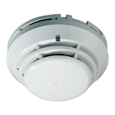
Kilsen KL710A Assembly instructions

© 2020 UTC Fire & Security. All rights reserved. 1 / 12 P/N 10-4221-501-KL7A-02 • ISS 05FEB20
KL710A, KL731A, and KL735A Addressable
Point Detectors Installation Sheet
EN ES FR IT NL PL PT TR
1
2
3
EN: Installation instructions
Installation
Caution: For general guidelines on system planning, design,
installation, commissioning, use and maintenance, refer to the
CEN/TS 54-14 standard and local regulations.
To install a detector
1. Insert the detector head into the mounting base and rotate
it clockwise until it clicks into place (Figure 1).
2. The detector may be locked into the mounting base if
required. To do this, remove the locking tab before
installation (Figure 2).
3. After installation, ensure that the detector communicates
with the control panel. If the detector does not
communicate with the control panel, check that duplicate
addresses have not been assigned.
4. Always test detectors after installation.
To remove a locked detector
1. Insert a small screwdriver into the locking tab slot
(Figure 3).
2. Press and rotate the detector anticlockwise.
Addressing
Each device requires a numeric address between 1 and 125
for identification purposes. This is assigned at the fire panel or
using a PG700N Device Programmer.

2 / 12 P/N 10-4221-501-KL7A-02 • ISS 05FEB20
Maintenance
Basic maintenance is reduced to a yearly inspection. Do not
modify internal wiring or circuitry.
Specifications
KL710A KL731A
KL731AB
KL735A
Operating voltage
22 to 38 VDC 22 to 38 VDC 22 to 38 VDC
Current
Standby (38V)
Alarm
250 µA
<11 mA
250 µA
<11 mA
350 µA
<5 mA
Pre
-alarm indication Flashing LED Flashing LED Flashing LED
Alarm indication
Constant LED
Constant LED Constant LED
Coverage
60 to 80 m2 60 to 80 m2 60 to 80 m2
IP rating
IP42 IP42 IP42
Compatib
le mounting
base
KZ700,
KZ705, KZ700,
KZ705,
KZ700B
KZ700,
KZ705,
Temperature:
Operation
Storage
−10 to +60ºC
−10 to +70ºC
−10 to +60ºC
−10 to +70ºC
−10 to +60ºC
−10 to +70ºC
Relative humidity
(noncondensing)
10 to 95% 10 to 95% 10 to 95%
Colour
White White/Black White
Dimensions (Ø × H )
99 × 45 mm 99 × 45 mm 99 × 51 mm
Weight
75 g 107 g 109 g
Regulatory information
This section provides a summary on the declared performance
according to the Construction Products Regulation
(EU) 305/2011 and Delegated Regulations (EU) 157/2014 and
(EU) 574/2014.
For detailed information, see the product Declaration of
Performance (available at firesecurityproducts.com).
Certification
Certification body
1134 1134 1134
Declaration of
Performance number
360-4222-
0399 360-4222-
0199 360-4222-
0499
Year of fir
st CE marking 05 05 06
Product Identification
KL710A KL731A
KL731ABKL735A
Intended use
See the product Declaration of
Performance
Declared performance
See the product Declaration of
Performance
Manufacturer
United Technologies Safety System Co.
Ltd., 80, Changjiang East Road,
QETDZ, Qinhuangdao, Hebei Province,
China 066004
Authorized EU manufacturing
representative: UTC Fire & Security B.V.
Kelvinstraat 7, 6003 DH Weert,
Netherlands
Contact information and product
documentation
For contact information or to download the latest product
documentation, visit firesecurityproducts.com.
Product warnings and disclaimers
THESE PRODUCTS ARE INTENDED FOR SALE TO AND
INSTALLATION BY QUALIFIED PROFESSIONALS. UTC
FIRE & SECURITY CANNOT PROVIDE ANY ASSURANCE
THAT ANY PERSON OR ENTITY BUYING ITS PRODUCTS,
INCLUDING ANY “AUTHORIZED DEALER” OR
“AUTHORIZED RESELLER”, IS PROPERLY TRAINED OR
EXPERIENCED TO CORRECTLY INSTALL FIRE AND
SECURITY RELATED PRODUCTS.
For more i
nformation on warranty disclaimers
and product safety information, please check
https://firesecurityproducts.com/policy/product
-
warning/
or scan the QR code:
ES: Instrucciones de instalación
Instalación
Precaución: Para información sobre el diseño, instalación,
uso y mantenimiento del sistema, aconsejamos seguir la
norma CEN/TS 54-14 y normas locales.
Para instalar el detector
1. Inserte el detector en la base y girar en sentido horario
hasta que encaje perfectamente (Figura 1).
2. El detector se puede bloquear en la base en caso de ser
necesario. Para ello, quitar la lengüeta antes de su
instalación (Figura 2).
3. Tras la instalación, asegurar que el detector comunica con
la central. Si el detector no comunica con la central,
verificar que no tenga asignada una dirección repetida.
4. Siempre realizar un test después de la instalación.
Para quitar un detector bloqueado
1. Insertar un pequeño destornillador en el orificio
(ver Figura 3).
2. Presionar y girar el detector en sentido anti-horario.
Direccionamiento
Cada dispositivo require de una dirección numérica entre el 1 y
el 125 para su identificación. Esta dirección se asigna en el
panel o empleando el programador portátil PG700N.
Mantenimiento
El mantenimiento del dispositivo consistirá en una inspección
tanto visual como de funcionamiento a realizar anualmente. No
deberá manipularse el interior del dispositivo.

P/N 10-4221-501-KL7A-02 • ISS 05FEB20 3 / 12
Especificaciones técnicas
KL710A KL731A
KL731AB
KL735A
Tensión de
alimentación
22 a 38 VDC 22 a 38 VDC 22 a 38 VDC
Corriente de consumo
Normal (38V)
Alarma
250 µA
<11 mA
250 µA
<11 mA
350 µA
<5 mA
Indicación de pre
-
a
larma LED
parpadeando LED
parpadeando LED
parpadeando
Indicación de alarma
LED constante LED constante LED constante
Cobertura
60 a 80 m260 a 80 m260 a 80 m2
IP rating
IP42 IP42 IP42
Bases compatibles
KZ700,
KZ705, KZ700, KZ705,
KZ700B KZ700, KZ705,
Temperatura:
Funcionamiento
Almacenaje
–10 a +60ºC
–10 a +70ºC
–10 a +60ºC
–10 a +70ºC
–10 a +60ºC
–10 a +70ºC
Humedad relativa (sin
condensación)
10 a 95% 10 a 95% 10 a 95%
Color
Blanco Blanco/Negro Blanco
Dimensiones (Ø × A )
99 × 45 mm 99 × 45 mm 99 × 51 mm
Peso
75 g 107 g 109 g
Información regulatoria
En esta sección se proporciona un resumen de las
prestaciones declaradas según el Reglamento sobre los
productos de construcción (UE) 305/2011 y los Reglamentos
delegados (UE) 157/2014 y (UE) 574/2014.
Para obtener información detallada, consulte la Declaración de
prestaciones (disponible en firesecurityproducts.com).
Certificación
Entidad de certificación
1134
1134
1134
Número de De
claración de
Prestaciones
360
-4222-
0399
360
-4222-
0199
360
-4222-
0499
Año inicial de marcado CE
05
05
06
Identificación de producto
KL710A
KL731A
KL731A
B
KL735A
Uso
s previstos
Consulte la
Declaración de prestaciones
del producto
Prestaciones declaradas
C
onsulte la Declaración de prestaciones
del producto
Fabricante
United
Technologies Safety System Co.
Ltd
., 80, Changjiang East Road, QETDZ,
Qinhuangdao,
Hebei Province, China
066004
Representante de fabricación autorizado
en Europa: UTC Fire & Security B
.V.,
Kelvinstraat 7, 6003 DH Weert, Países
Bajos
Información de contacto y documentación
del producto
Para conocer la información de contacto o para descargar la
última documentación del producto, visite
firesecurityproducts.com.
Advertencias y declaraciones sobre el
producto
ESTOS PRODUCTOS ESTÁN DESTINADOS A LA VENTA E
INSTALACIÓN POR UN PROFESIONAL DE SEGURIDAD
EXPERIMENTADO. UTC FIRE & SECURITY NO PUEDE
GARANTIZAR QUE TODA PERSONA O ENTIDAD QUE
COMPRE SUS PRODUCTOS, INCLUYENDO CUALQUIER
«DISTRIBUIDOR O VENDEDOR AUTORIZADO», CUENTE
CON LA FORMACIÓN O EXPERIENCIA PERTINENTE PARA
INSTALAR CORRECTAMENTE PRODUCTOS
RELACIONADOS CON LA SEGURIDAD.
Para obtener más información sobre
exclusiones de garantía e in
formación de
seguridad de productos, consulte
https://fire
securityproducts.com/policy/product
-warning/ o
escanee el código QR:
FR: Instructions d'installations
Installation
Attention: Suivant les directives générales pour l’installation,
la mise en service et la maintenance, référez vous à la
directive CEN/TS 54-14.
Pour installer le détecteur
1. Insérer la tête du détecteur dans le montage de base et le
faire pivoter vers la droite jusqu'à sa fixation. (Figure 1).
2. Le détecteur doit être verrouillé dans de base si
nécessaire. Pour ce faire supprimer l'onglet de
verrouillage avant l'installation (Figure 2).
3. Après l’installation, assurez-vous que le détecteur
communique avec la centrale. Si le détecteur ne
communique pas avec la centrale, assurez-vous qu’il n’y a
pas de doubles adresses.
4. Effectuer toujours un essai après l'installation du
détecteur.
Pour supprimer un détecteur
1. Insérez un petit tournevis dans la fente de verrouillage
onglet (Figure 3).
2. Presser et faites pivoter le détecteur dans le sens anti-
horlogique.
Addressage
Chaque élément exige une adresse numérique entre 1 et 125
pour son identification. Ceci est assigné à la centrale ou en
utilisant un programmeur portatif d'adressage PG700N.

4 / 12 P/N 10-4221-501-KL7A-02 • ISS 05FEB20
Maintenance
La maintenance de base se limite à une inspection annuelle.
Ne pas modifier le câblage interne.
Caractéristiques techniques
KL710A KL731A
KL731AB
KL735A
Tension
22 à 38 VDC 22 à 38 VDC 22 à 38 VDC
Courrant
Repose
Alarme
250 µA
<11 mA
250 µA
<11 mA
350 µA
<5 mA
Indication de pré
-
alarme
LED clignotante
LED
clignotante LED clignotante
Indication d’alarme
LED constante LED constante LED constante
Couverture
60 à 80 m260 à 80 m260 à 80 m2
IP
IP42 IP42 IP42
Base du détecteur
KZ700, KZ705,
KZ700, KZ705,
KZ700B KZ700, KZ705,
Température
Utilisation
Stockage
–10 à +60ºC
–10 à +70ºC
–10 à +60ºC
–10 à +70ºC
–10 à +60ºC
–10 à +70ºC
Humidité relative
(
sans condensation) 10 à 95% 10 à 95% 10 à 95%
Coulour
Blanc Blanc/Noir Blanc
Dimensions (Ø × H )
99 × 45 mm 99 × 45 mm 99 × 51 mm
Poids
75 g 107 g 109 g
Informations sur la réglementation
Cette section constitue un résumé de la déclaration des
performances. Cette dernière est établie conformément au
règlement (UE) 305/2011 relatif aux produits de construction,
ainsi qu’aux règlements délégués (UE) 157/2014 et
(UE) 574/2014.
Pour obtenir des informations détaillées, consultez la
déclaration des performances à l’adresse
firesecurityproducts.com.
Certification
Organisme de certification
1134 1134 1134
Numéro de la
déclaration
des performances
360-4222-
0399 360-4222-
0199 360-4222-
0499
Année du premier
marquage CE
05 05 06
Identification du produit
KL710A KL731A
KL731AB KL735A
Usage prévu
Voir la déclaration des performances
Performance déclarée
Voir la déclaration des performances
Fabricant
United Technologies Safety System Co.
Ltd., 80, Changjiang East Road,
QETDZ,
Qinhuangdao, Hebei Province, Chine
066004
Représentant européen du fabricant :
UTC Fire & Security B.V. Kelvinstraat 7,
6003 DH Weert, Pays-Bas
Coordonnées et documentation
Pour obtenir nos informations de contact ou télécharger la
documentation la plus récente sur le produit, rendez-vous à
l’adresse firesecurityproducts.com.
Avertissements et avis de non-
responsabilité
CES PRODUITS SONT DESTINÉS À DES
PROFESSIONNELS EXPÉRIMENTÉS, QUI DOIVENT
ÉGALEMENT SE CHARGER DE LEUR INSTALLATION. UTC
FIRE & SECURITY NE PEUT GARANTIR QU’UNE
PERSONNE OU ENTITÉ FAISANT L’ACQUISITION DE
CEUX-CI, Y COMPRIS UN REVENDEUR AGRÉÉ, DISPOSE
DE LA FORMATION OU DE L’EXPÉRIENCE REQUISE
POUR PROCÉDER À CETTE MÊME INSTALLATION DE
FAÇON APPROPRIÉE.
Pour obtenir des informations supplémentaires
sur les garanties et la sécurité, rendez
-vous à
l’adresse
https://firesecurityproducts.com/policy/
product
-warning/ ou scannez le code QR :
IT: Istruzioni di installazione
Installazione
Attenzione: per indicazioni di carattere generale inerenti la
configurazione del sistema, il progetto, l’installazione, la messa
in funzione, l’utilizzo e la manutenzione riferirsi alla direttiva
standard CEN/TS 54-14 e alle normative locali.
Installare il rivelatore
1. Inserire il rivelatore nella base di montaggio e ruotarlo fino
a quando non scatta (Figura 1).
2. Il rivelatore può essere bloccato nella base di montaggio,
se richiesto. Per attivare il blocco, rimuovere la linguetta
prima dell’installazione del rivelatore (Figura 2).
3. Dopo l’installazione, assicurarsi che il rivelatore comunichi
con la centrale. Se il rivelatore non comunica con la
centrale, verificare che non sia stato assegnato un doppio
indirizzo.
4. Provare sempre i rivelatori dopo l’installazione.
Rimuovere un rivelatore bloccato
1. Inserire un piccolo cacciavite nella fessura presente nella
base (Figura 3).
2. Premere e ruotare il rivelatore in senso antiorario.
Indirizzamento
Ogni dispositivo richiede un indirizzo compreso tra 1 e 125 per
ll’identificazione. L’indirizzo può essere assegnato dalla
centrale o usando il PG700N indirizzatore portatile.
Manutenzione
La manutenzione richiesta è stata ridotta ad una ispezione
all’anno. Non modificare i collegamenti interni o la circuiteria.

P/N 10-4221-501-KL7A-02 • ISS 05FEB20 5 / 12
Specifiche tecniche
KL710A KL731A
KL731AB
KL735A
Aliment
azione Da 22 a 38 Vcc Da 22 a 38 Vcc Da 22 a 38 Vcc
Assorbimento
Riposo (38V)
Allarme
250 µA
<11 mA
250 µA
<11 mA
350 µA
<5 mA
Indicazione
preallarme
LED
lampeggianti LED
lampeggianti LED
lampeggianti
Indicazione allarme
LED accesi LED accesi LED accesi
Copertura
Da 60 a 80 m2Da 60 a 80 m2Da 60 a 80 m2
Grado di protezione
IP42 IP42 IP42
Basi
KZ700, KZ705, KZ700, KZ705,
KZ700B KZ700, KZ705,
Temperatura:
di lavoro
di stoccaggio
Da –10 a +60ºC
Da –10 a +70ºC
Da –10 a +60ºC
Da –10 a +70ºC
Da –10
a +60ºC
Da –10
a +70ºC
Umidità relative
(senza condensa)
Da 10 a 95% Da 10 a 95% Da 10 a 95%
Colore
Bianco Bianco/Nero Bianco
Dimensioni (Ø × H )
99 × 45 mm 99 × 45 mm 99 × 51 mm
Peso
75 g 107 g 109 g
Informazioni sulle normative
Questa sezione fornisce un riepilogo delle prestazioni
dichiarate in base al regolamento dei prodotti da costruzione
(UE) 305/2011 e ai regolamenti delegati (UE) 157/2014 e
(UE) 574/2014.
Per informazioni dettagliate, consultare la Dichiarazione di
prestazione (DoP) del prodotto (disponibile al sito
firesecurityproducts.com).
Certificazione
Organismo di certificazione
1134 1134 1134
Numero della
Dichiarazione di
p
restazione
360-4222-
0399 360-4222-
0199 360-4222-
0499
Anno della prima
marcatura CE
05 05 06
Identificazione del prodotto
KL710A KL731A,
KL731ABKL735A
Uso previsto
Consultare la Dichiarazione di
prestazione (DoP) del prodotto
Prestazioni dichiarate
Consultare la Dichiarazione di
prestazione (DoP) del prodotto
Produttore
United Technologies Safety System Co.
Ltd
., 80, Changjiang East Road, QETDZ,
Qinhuangdao, Hebei Province, China
066004
Rappresentante di produzione
autorizzato per EU:
UTC Fire & Security B.V.
Kelvinstraat 7, 6003 DH Weert, Paesi
Bass
Informazioni di contatto e documentazione
del prodotto
Per informazioni di contatto o per scaricare la documentazione
del prodotto più recente, visitare firesecurityproducts.com.
Avvertenze sul prodotto e dichiarazioni di
non responsabilità
QUESTI PRODOTTI SONO DESTINATI ALLA VENDITA A, E
DEVONO ESSERE MONTATI DA, UN ESPERTO
QUALIFICATO. UTC FIRE & SECURITY NON PUÒ
GARANTIRE CHE LE PERSONE O GLI ENTI CHE
ACQUISTANO I SUOI PRODOTTI, COMPRESI I
"RIVENDITORI AUTORIZZATI", DISPONGANO DELLA
FORMAZIONE O DELL'ESPERIENZA ADEGUATE PER
ESEGUIRE LA CORRETTA INSTALLAZIONE DI PRODOTTI
PER LA SICUREZZA E PER LA PROTEZIONE
ANTINCENDIO.
Per ulteriori informazioni sulle esclusioni di
garanzia e sulla sicurezza dei prodot
ti,
consultare il sito
https://firesecurityproducts.com
/policy/product
-warning/ oppure eseguire la
scansione del codice QR:
NL: Installatie instructies
Installatie
Waarschuwing: Voor algemene voorschriften voor systeem
planning, ontwerp, installatie, in bedrijf stellen, gebruik en
onderhoud, verwijzen we naar de CEN/TS 54-14 standaards
and lokale regelgeving.
Een detector installeren
1. Druk de detector in de montagevoet en draai hem met de
klok mee totdat men een klik hoort (Figuur 1).
2. De detector kan worden geblokkeerd in de montagevoet
indien nodig. Om dit te doen verwijder het
blokkeermechanisme voor de installatie (Figuur 2).
3. Na installatie , moet de detector communiceren met het
brandmeldpaneel. Als de detector niet communiceerd
controleer dan of er geen dubbele adressen zijn en
corigeer zonodig.
4. Test een detector altijd na installatie.
Het verwijderen van een geblokkeerde detector
1. Steek een smalle schroevendraaier in het gaatje aan de
zijkant van de detector (Figuur 3).
2. Druk en draai de detector tegen de klok in.
Adressering
Iedere detector moet een numeriek adres krijgen tussen de 1
en de 125 voor identificatie. Deze adressen worden toegekend
door het brandmeldpaneel of met de programeer unit PG700N.

6 / 12 P/N 10-4221-501-KL7A-02 • ISS 05FEB20
Onderhoud
Basis onderhoud is verminderd tot een jaarlijkse inspectie.
Wijzig geen interne bedrading of circuits.
Technische specificaties
KL710A KL731A
KL731AB
KL735A
Spanning
22 tot 38 VDC 22 tot 38 VDC 22 tot 38 VDC
Stroomverbruik
Rust
Alarm
250 µA
<11 mA
250 µA
<11 mA
350 µA
<5 mA
Voor
-alarm indicatie Knipperende
LED Knipperende
LED Knipperende
LED
Alarm indicatie
Constante LED Constante
LED Constante LED
Bereik
60 tot 80 m260 tot 80 m260 tot 80 m2
IP klasse
IP42 IP42 IP42
Bijbehorende
montagevoet
KZ700, KZ705,
KZ700, KZ705,
KZ700B KZ700, KZ705,
Temperatuur
In bedrijf
Opgeslagen
–10 tot +60ºC
–10 tot +70ºC
–10 tot +60ºC
–10 tot +70ºC
–10 tot +60ºC
–10 tot +70ºC
Relatieve vochtigheid
(
geen condensatie) 10 tot 95% 10 tot 95% 10 tot 95%
Kleur
Wit Wit/Zwart Wit
Afmetingen
(Ø × H ) 99 × 45 mm 99 × 45 mm 99 × 51 mm
Gewicht
75 g 107 g 109 g
Van toepassing zijnde normen
Dit gedeelte geeft een samenvatting van de aangegeven
prestaties conform de Verordening Bouwproducten
(EU) 305/2011 en Gedelegeerde Verordeningen
(EU) 157/2014 en (EU) 574/2014.
Zie de Prestatieverklaring van het product voor gedetailleerde
informatie (beschikbaar op firesecurityproducts.com).
Certificatie
Certificerings instelling
1134 1134 1134
Nummer van
Prestatieverklaring
360-4222-
0399 360-4222-
0199 360-4222-
0499
Jaar van de eerste CE
-
certificering
05 05 06
Productidentificatie
KL710A KL731A
KL731ABKL735A
Bed
oeld gebruik Zie de Prestatieverklaring van het
product
Aangegeven prestaties
Zie de Prestatieverklaring van het
product
Fabrikant
United Technologies Safety System Co.
Ltd., 80, Changjiang East Road, QET
DZ,
Qinhuangdao, Hebei Province, China
066004
EU-geautoriseerde vertegenwoordiger:
UTC Fire & Security B.V., Kelvinstraat 7,
6003 DH Weert, Nederland
Contactgegevens en productdocumentatie
Ga naar firesecurityproducts.com voor contactgegevens of om
de nieuwste productdocumentatie te downloaden.
Waarschuwingen en disclaimers met
betrekking tot de producten
DEZE PRODUCTEN ZIJN BEDOELD VOOR VERKOOP AAN
EN INSTALLATIE DOOR GEKWALIFICEERDE
BEROEPSKRACHTEN. UTC FIRE & SECURITY GEVEN
GEEN GARANTIE DAT EEN PERSOON OF ENTITEIT DIE
DIENS PRODUCTEN AANSCHAFT, WAARONDER
“GEAUTORISEERDE DEALERS” OF "GEAUTORISEERDE
WEDERVERKOPERS", OP DE JUISTE WIJZE ZIJN
OPGELEID OF VOLDOENDE ERVARING HEBBEN OM
PRODUCTEN MET BETREKKING TOT BRAND EN
BEVEILIGING OP DE JUISTE WIJZE TE INSTALLEREN.
Zie
voor meer informatie over
garantiebepalingen en productveiligheid
https://firesecurityproducts.com/policy/product
-
warning/
of scan de QR-code:
PL: Instrukcje instalacji
Instalacja
Uwaga: Należy przestrzegać lokalnych i ogólnych (CEN/TS
54-14) przepisów dotyczących planowania, projektowania,
instalowania i konserwacji systemu.
Aby zainstalować czujkę należy
1. Włożyć głowicę czujki do podstawy montażowej i
przekręcić zgodnie z ruchem wskazówek zegara, aż do
zatrzaśnięcia (Rysunek 1).
2. Głowica czujki może zostać zablokowana w podstawie
montażowej, jeśli zachodzi taka potrzeba. Aby tego
dokonać, należy przed instalacją usunąć zawleczkę
blokującą (Rysunek 2).
3. Po zainstalowaniu czujki upewnij się, że komunikacja
pomiędzy centralą i czujką przebiega prawidłowo. W
przeciwnym przypadku należy sprawdzić czy w systemie
nie zostały zduplikowane adresy urządzeń.
4. Zawsze należy przetestować czujki po instalacji.
Aby wymontować zablokowaną czujkę należy
1. Wsunąć końcówkę cienkiego wkrętaka w otwór zwolnienia
blokady (Rysunek 3).
2. Przytrzymując wkrętak wsunięty w otwór, należy obrócić
czujkę w kierunku przeciwnym do ruchu wskazówek
zegara.
Adresowanie
Każda czujka identyfikowana jest w systemie za pomocą
adresu z zakresu 1 – 125, który można nadać czujce z
poziomu menu centrali lub przy pomocy programatora czujek
PG700N.

P/N 10-4221-501-KL7A-02 • ISS 05FEB20 7 / 12
Konserwacja
Konserwacja jest ograniczona do corocznych przeglądów. Nie
należy dokonywać żadnych zmian w konstrukcji podstaw lub w
okablowaniu.
Dane techniczne
KL710A KL731A
KL731AB
KL735A
Napięcie zasilające
Od 22 do 38
V DC Od 22 do 38
V DC Od 22 do 38
V DC
Prąd
Spoczynkowy
W alarmie
250 µA
<11 mA
250 µA
<11 mA
350 µA
<5 mA
Sygnalizacja stanu
przedalarmowego
Migająca dioda
LED Migająca
dioda LED
Migająca dioda
LED
Sygnalizacja stanu
alarmowego
Świecąca dioda
LED Świecąca
dioda LED
Świecąca dioda
LED
Pokrycie
60 do 80 m260 do 80 m260 do 80 m2
Klasa IP
IP42 IP42 IP42
Kompatybilne
podstawy montażowe
KZ700, KZ705,
KZ700,
KZ705,
KZ700B
KZ700, KZ705,
Temperatura
Robocza
Przechowywania
–10 do +60ºC
–10 do +70ºC
–10 do +60ºC
–10 do +70ºC
–10 do +60ºC
–10 do +70ºC
Wil
gotność względna
(bez kondensacji)
10 do 95% 10 do 95% 10 do 95%
Kolor
Biały Biały/Czarny Biały
Wymiary (Ø × H )
99 × 45 mm 99 × 45 mm 99 × 51 mm
Waga
75 g 107 g 109 g
Informacje prawne
W tej sekcji przedstawiono deklarowane właściwości użytkowe
zgodnie z rozporządzeniem UE 305/2011 dotyczącym
produktów budowlanych oraz rozporządzeniami delegowanymi
UE 157/2014 i 574/2014.
Szczegółowe informacje podano w Deklaracji właściwości
użytkowych dostępnej na stronie firesecurityproducts.com.
Certyfikat
Organ certyfikujący
1134 1134 1134
Numer Deklaracji
Właściwości Użytkowych
360-4222-
0399 360-4222-
0199 360-4222-
0499
Rok pierwszego
oznakowania CE
05 05 06
Identyfikacja produktu
KL710A KL731A,
KL731AB KL735A
Przeznaczenie
Patrz Deklaracja właściwości użytkowych
Deklarowane właściwości
użytkowe
Patrz Deklaracja właściwości użytkowych
Producent
United Technologies Safety System Co.
Ltd.
, 80, Changjiang East Road, QETDZ,
Qinhuangdao, Hebei Province, Chiny
066004
Autoryzowany przedstaw
iciel producenta
na terenie UE: UTC Fire & Security B.V,
Kelvinstraat 7, 6003 DH Weert,
Niderlandy
Informacje kontaktowe i dokumentacja
produktu
Aby uzyskać informacje kontaktowe lub pobrać najnowszą
dokumentację produktu, odwiedź witrynę
firesecurityproducts.com.
Ostrzeżenia i zastrzeżenia dotyczące
produktu
TEN PRODUKT JEST PRZEZNACZONY DO SPRZEDAŻY I
MONTAŻU PRZEZ WYKWALIFIKOWANYCH
SPECJALISTÓW. UTC FIRE & SECURITY NIE UDZIELA
ŻADNEJ GWARANCJI, ŻE JAKAKOLWIEK OSOBA LUB
JAKIKOLWIEK PODMIOT NABYWAJĄCY JEJ PRODUKTY,
W TYM „AUTORYZOWANI SPRZEDAWCY” ORAZ
„AUTORYZOWANI DEALERZY”, SĄ PRAWIDŁOWO
PRZESZKOLENI LUB DOŚWIADCZENI TAK, BY MOGLI
PRAWIDŁOWO ZAMONTOWAĆ PRODUKTY
ZABEZPIECZAJĄCE.
Więcej informacji o zastrzeżeniach dotyczących
gwarancji oraz bezpieczeństwa produktów
można przeczytać na stronie
https://firesecurity
products.com/policy/product
-warning/ lub po
zeskanowaniu kodu QR:
PT: Instruções de instalação
Instalação
Advertência: Para informação geral sobre planeamento do
sistema, arquitectura, instalação, configuração, utilização e
manutenção, consulte a norma CEN/TS 54-14 ou a
regulamentações locais.
Para instalar o detector
1. Insira do detector na base e rode no sentido dos ponteiros
do relógio, até fixar. (Figura 1).
2. O detector pode ser bloqueado na base se necessário.
Para bloquear, remova o ponto de bloqueio (Figura 2).
3. Após a instalação, certifique-se de que o detector
comunica com o painel de controlo. Se o detector não
comunicar com o painel de controlo, verifique se não
existem endereços duplos.
4. Teste sempre os detectores após instalação.
Para remover um detector bloqueado
1. Insira uma chave de fendas pequena na ranhura (Figura
3).
2. Pressione e rode o detector no sentido contrário aos
ponteiros do relógio.
Endereçamento
Cada dispositivo requer um endereço de identificação único,
compreendido entre 1 e 125. Este endereço pode ser atribuído
através do painel de controlo ou através do programador
portátil PG700N.

8 / 12 P/N 10-4221-501-KL7A-02 • ISS 05FEB20
Manutenção
A manutenção básica encontra-se reduzida a uma inspecção
anual. Não modificar as ligações ou circuitos internos.
Especificações Técnicas
KL710A KL731A
KL731AB
KL735A
Tensão
22 a 38 VDC 22 a 38 VDC 22 a 38 VDC
Consumo
Standby
Alarma
250 µA
<11 mA
250 µA
<11 mA
350 µA
<5 mA
Indicação Pré
-alarme LED a piscar LED a piscar LED a piscar
Indicação de alarme
LED aceso LED aceso LED aceso
Cobertura
60 a 80 m260 a 80 m260 a 80 m2
Índice de protecção
IP42 IP42 IP42
Base compatível
KZ700, KZ705,
KZ700, KZ705,
KZ700B KZ700, KZ705,
Temperatura
Operação
Armazenamento
–10 a +60ºC
–10 a +70ºC
–10 a +60ºC
–10 a +70ºC
–10 a +60ºC
–10 a +70ºC
Humidade relativa
(
não condensado) 10 a 95% 10 a 95% 10 a 95%
Color
Branco Branco/Preto Branco
Dimensões
(Ø × A) 99 × 45 mm 99 × 45 mm 99 × 51 mm
Peso
75 g 107 g 109 g
Informação reguladora
Esta secção apresenta um resumo da declaração de
desempenho conforme o Regulamento relativo aos Produtos
de Construção (UE) 305/2011 e os Regulamentos Delegados
(UE) 157/2014 e (UE) 574/2014.
Para informações detalhadas, consulte a Declaração de
desempenho do produto (disponível em
firesecurityproducts.com).
Certificação
Organismo de Certificação
1134 1134 1134
Número da declaração de
desempenho
360-4222-
0399 360-4222-
0199 360-4222-
0499
Ano da primeira marca CE
05 05 06
Identificação do produto
KL710A KL731A
KL731AB KL735A
Utilização prevista
Consulte a Declaração de desempenho
do produto
Declaração de
desempenho
Consulte a Declaração de desempenho
do produto
Fabricante
United Technologies Safety System Co.
Ltd.
, 80, Changjiang East Road, QETDZ,
Qinhuangdao, Hebei Province, China
066004
Representante de fabrico autorizado na
UE: UTC Fire & Security B.V.
Kelvinstraat 7, 6003 DH Weert, Holanda
Informações de contato e documentação do
produto
Para obter informações de contato ou para transferir a
documentação mais recente do produto, visite firesecurity
products.com.
Avisos e isenções de responsabilidade dos
produtos
ESTES PRODUTOS DESTINAM-SE A SER VENDIDOS E
INSTALADOS POR PROFISSIONAIS QUALIFICADOS. A
UTC FIRE & SECURITY NÃO PODE APRESENTAR
QUALQUER GARANTIA DE QUE QUALQUER PESSOA OU
ENTIDADE QUE COMPRE OS SEUS PRODUTOS,
INCLUINDO QUALQUER “DISTRIBUIDOR AUTORIZADO”
OU “REVENDEDOR AUTORIZADO”, TEM FORMAÇÃO OU
EXPERIÊNCIA ADEQUADA PARA INSTALAR
CORRETAMENTE PRODUTOS RELACIONADOS COM A
SEGURANÇA E A PROTEÇÃO CONTRA INCÊNDIOS.
Para mais informações sobre isenções de
garantia e sobre a segurança dos produtos,
consulte
https://firesecurityproducts.com/policy/
product
-warning/ ou faça a leitura do código
QR:
TR: Montaj notları
Montaj
Uyarı: Genel sistem dizaynı , montaj , devreye alma , işletme
ve bakımı CEN/TS 54-14 standardı ve yerel tüzükler
gözönünde bulundurularak yapılacaktır.
Dedektör montajı
1. Dedektörü, tabanına oturtarak saat yönünde yerleşme sesi
gelene kadar çeviriniz. (Tablo 1).
2. İstenirse dedektör, tabanına kilitli kalacak pozisyonda
bırakılabilir. Bunu yapmak için dedektörü monte etmeden
once kilitleme etiketini çıkartınız. (Tablo 2).
3. Devreye aldıktan sonra , dedektörün kontrol paneli ile
haberleştiğinden emin olunuz. Eğer detektör , kontrol
paneli ile haberleşmiyorsa, çift adresin atanmadığından
emin olunuz.
4. Mutlaka dedektör montajı bittikten sonra doğruluğunu test
ediniz.
Tabanına kilitlenmiş dedektörü sökmek için
1. Kilitleme etiketine küçük bir tornavida sokunuz. (Tablo 3)
2. Etikete basarak dedektörü saat yönünün tersinde çeviriniz.
Adresleme
Her cihaz 1 ile 125 arasında, tanımlama amaçlı sayısal bir
adrese ihtiyaç duyar. Adres atama işlemi yangın panelinden
veya PG700N portatif programlama cihazı ile gerçekleştirilir.

P/N 10-4221-501-KL7A-02 • ISS 05FEB20 9 / 12
Bakım
Genel olarak bakım yıllık kontrollerde yapılabilir. Dahili
kablolamayı lütfen hiçbir şekilde değiştirmeyiniz.
Özellikler
KL710A KL731A
KL731AB KL735A
İşletme gerilimi
22 ile 38 VDC 22 ile 38 VDC 22 ile 38 VDC
Akım
Sukunet
Alarm
250 µA
<11 mA
250 µA
<11 mA
350 µA
<5 mA
Ön
-alarm durumu Yanıp sönen
LED Yanıp sönen
LED Yanıp sönen
LED
Alarm durumu
Sürekli yanan
LED Sürekli yanan
LED Sürekli yanan
LED
Etkili olduğu alan
60 ile 80 m260 ile 80 m260 ile 80 m2
IP değeri
IP42 IP42 IP42
Uyumlu dedektör
tabanı
KZ700, KZ705,
KZ700, KZ705,
KZ700B KZ700, KZ705,
Sıcaklık
İşletme
Depolama
–10 ile +60ºC
–10 ile +70ºC
–10 ile +60ºC
–10 ile +70ºC
–10 ile +60ºC
–10 ile +70ºC
Gerçek nem
(yoğuşmasız)
10 to 95% 10 to 95% 10 to 95%
Renk
Beyaz Beyaz/Siyah Beyaz
Boyutlar (Ø × H )
99 × 45 mm 99 × 45 mm 99 × 51 mm
Ağırlık
75 g 107 g 109 g
Düzenleyici bilgiler
Bu bölüm, Yapı Ürünleri Yönetmeliği (AB) 305/2011 ve Yetkili
Yönetmelikler (AB) 157/2014 ve (AB) 574/2014'e göre tanımlı
performansa ilişkin bir özet sağlar.
Ayrıntılı bilgi için ürünün Performans Bildirimine bakın
(firesecurityproducts.com adresinden ulaşılabilir).
Sertifikalar
Belgelendirme kuruluşu
1134 1134 1134
Performans Bildirimi
numarası
360-4222-
0399 360-4222-
0199 360-4222-
0499
İlk CE işareti Yılı
05 05 06
Ürün tanımlama
KL710A KL731A
KL731ABKL735A
Kullanım amacı
Ürünün Performans Bildirimi'ne bakın
Tanımlı perfor
mans Ürünün Performans Bildirimi'ne bakın
Üretici
United Technologies Safety System Co.
Ltd.
, 80, Changjiang East Road, QETDZ,
Qinhuangdao, Hebei Province, Çin
066004
EU yetkili üretim temsilcisi:
UTC Fire & Security B.V., Kelvinstraat 7,
6003 DH Weert, Hollanda
İletişim bilgileri ve ürün belgeleri
İletişim bilgileri veya en güncel ürün belgelerini indirmek için
firesecurityproducts.com adresini ziyaret ediniz.
Ürün uyarıları ve feragatler
BU ÜRÜNLER NİTELİKLİ UZMANLARA SATILMAK VE
NİTELİKLİ UZMANLAR TARAFINDAN MONTE EDİLMEK
ÜZERE TASARLANMIŞTIR. UTC FIRE & SECURITY,
HERHANGİ BİR “YETKİLİ BAYİ” VEYA “YETKİLİ SATICI” DA
DAHİL OLMAK ÜZERE ÜRÜNLERİNİ SATIN ALAN
KİŞİLERİN VEYA KURULUŞLARIN YANGIN VE
GÜVENLİKLE İLGİLİ ÜRÜNLERİ DOĞRU ŞEKİLDE MONTE
ETMEK ÜZERE GEREKLİ EĞİTİME VEYA DENEYİME SAHİP
OLDUĞU KONUSUNDA HERHANGİ BİR GARANTİ
VEREMEZ.
Garanti feragatleri ve ürün güvenliğine ilişkin
bilgiler hakkında daha fazla bilgi için lütfen
https://firesecurityproducts
.com/policy/product-
warning/
adresini ziyaret edin veya QR kodunu
taratın:

10 / 12 P/N 10-4221-501-KL7A-02 • ISS 05FEB20

P/N 10-4221-501-KL7A-02 • ISS 05FEB20 11 / 12

12 / 12 P/N 10-4221-501-KL7A-02 • ISS 05FEB20
Other manuals for KL710A
1
This manual suits for next models
2
Table of contents
Other Kilsen Security Sensor manuals
Popular Security Sensor manuals by other brands

Eaton
Eaton EF-CBD130 Installation and operation manual

APRVTIO
APRVTIO ALD-300 quick start guide

National Instruments
National Instruments USB-5683 Specifications

GEV
GEV TITAN 016835 User instructions

Nice
Nice Silentron Sil Bus 4081 Instructions and warnings for installation and use

Omron
Omron Sti F3SJ-E N25 Series user manual

Salewa
Salewa ORTLES user manual

System Sensor
System Sensor B501AUS Installation and maintenance instructions

Alarmtech
Alarmtech MC 746-E instruction manual

Saferhomee
Saferhomee HB-T001Q3 user manual

Docklands
Docklands GX360 Installation and operating instructions

M-E
M-E VISTUS AUDIO operating instructions