Kinder Limours User guide

Limours
Balanced Flue Room Heater
MODEL NUMBER : KBFP00RN
INS ALLA ION, USER AND SERVICING INS RUC IONS
THESE INSTRUCTIONS MUST REMAIN WITH THE USER
This appliance is suitable for use on Natural Gas (G20) at a supply pressure of
20mbar in G.B. / I.E. only.
0087

2
HIS APPLIANCE MEE S HE REQUIREMEN S OF HE EUROPEAN GAS DIREC IVE
Contents
age No.
List of components 3
Appliance Data 3
GENERAL INS ALLA ION REQUIREMEN S 3
Fitting the Appliance 3
lacing of Decorative Refractory Shapes 9
COMMISSIONING 10
USERS GUIDE 11
Useful tips & recommendations 11
Operation of the fire 11
Opening and Closing the Fascia anel 11
Lighting the Appliance 12
Cleaning the fire 13
SERVICING & MAIN ENANCE 14
Spares arts list 16
Important Notes – lease read before undertaking the installation
1. This is not a “Do it yourself” product and it must be installed by a
competent person.
2. The Installation Instructions must be adhered to without exception.
3. The heat from this appliance will cause the wall directly above the
appliance to become quite hot. If there is any concern about the
integrity of the plaster or wall finish, we recommend that slips made
from heat resistant material are fitted to cover the wall for at least
100mm above the top of the inner fascia panel. Any remedial
plasterwork above the appliance should be allowed to thoroughly dry
before lighting the appliance. remixed packet mortars should not be
used as the inhibitors incorporated in these products can cause
continual shrinkage after setting.

3
LIS OF COMPONEN S
Before commencing the installation ensure that all the components listed below
are included in the appliance packaging.
a) Balanced Flue Convector
b) Ceramic components; i) 1 acket Black Ceramic Granules
ii) 1 acket of 12 ‘Cotswold Stone’ ieces
iii) 1 acket of 22 ‘Cotswold Stone’ ieces
c) Flue and Terminal
d) Terminal guard
e) Aluminium Foil Tape, flue sealing rope gasket and fittings pack
f) Installation & Servicing and Instructions
g) Remote Control Handset & Receiver, 4 AA & 1 3 size alkaline batteries.
h) 2 rolls of white foam tape
Before commencing the installation ensure that all the components listed below
are included in the fascia packaging.
a) Fascia anel
b) Decorative trim and 4 magnets (if ordered)
Inset Installations only
a) Wall plate (must be used for Inset Installations)
APPLIANCE DA A:
KBFP00RN
GAS YPE NATURAL GAS
SUPPLY PRESSURE 20 mbar
HEA INPU 4.5 kW Gross
GAS RA E 0.43m3/h
INJEC OR SIZE Ø 1.6 mm
GAS CONNEC ION 8mm
WEIGH 40Kg
NOX Concentration Class 5
GENERAL INS ALLA ION REQUIREMEN S
Fitting the Appliance
1 The law demands that all gas appliances are installed by a qualified installer in
accordance with the current GAS SAFE Y (INS ALLA ION AND USE)
REGULA IONS. The installation must comply with these installation
instructions and all relevant parts of Local and National Building Standards
(Scotland) (Consolidation) Regulations and those relevant recommendations of
the following British Standards. BS 5871: art 1 BS 8303 BS 5440: arts
1 & 2 BS 6891 BSEN1856 arts 1 & 2 BS 5482 art 1, as well as
IGE/U /7.

4
2 The appliance can be fitted onto and inset into outside walls where the terminal
does fall into any of the prohibited positions mentioned in the next section. The
centre of the glass window is 157mm below the centre of the flue terminal. The
centre of the terminal should be positioned at least 700mm above floor level to
allow space for the fascia to drop down on its runners. If the fireplace has to be
altered a lintel will be required to support masonry over the opening and if it is
to be surface mounted the maximum wall thickness allowed is 405mm. If the
appliance is to be inset into the wall this may be increased to 525mm. If
required, a longer flue duct is available which allows the maximum wall
thicknesses to be increased to 800mm for the surface mount installation and
920mm for the inset installation.
3 Flue erminal Position
The minimum distances permissible from the flue terminal to obstructions and
ventilation openings are shown below.
DIMENSION
TERMINAL OSITION MINIMUM
DISTANCE
A Directly below an opening, air brick or window, etc. 300mm
B Above an opening, air brick, opening windows, etc. 300mm
C Horizontally to an opening, air brick, opening windows,
etc.
300mm
D Below plastic gutters, soil pipes or drain pipes 300mm
E Below eaves 300mm
F Below balconies or car port roof. 600mm
G From a vertical drainpipe or soil pipe. (Eire only 75) (GB) 300mm
H From an internal or external corner. 600mm
I Above ground, roof or balcony level. 300mm
J From a surface facing the terminal. 600mm
K From a terminal facing a terminal. 600mm
L From an opening in a carport (e.g. door, window) into the
dwelling.
1200mm
M Vertically from a terminal on the same wall. 1500mm
N Horizontally from a terminal on the same wall. 300mm
Not shown From an opening in a building directly opposite. 600mm
Figure 1

5
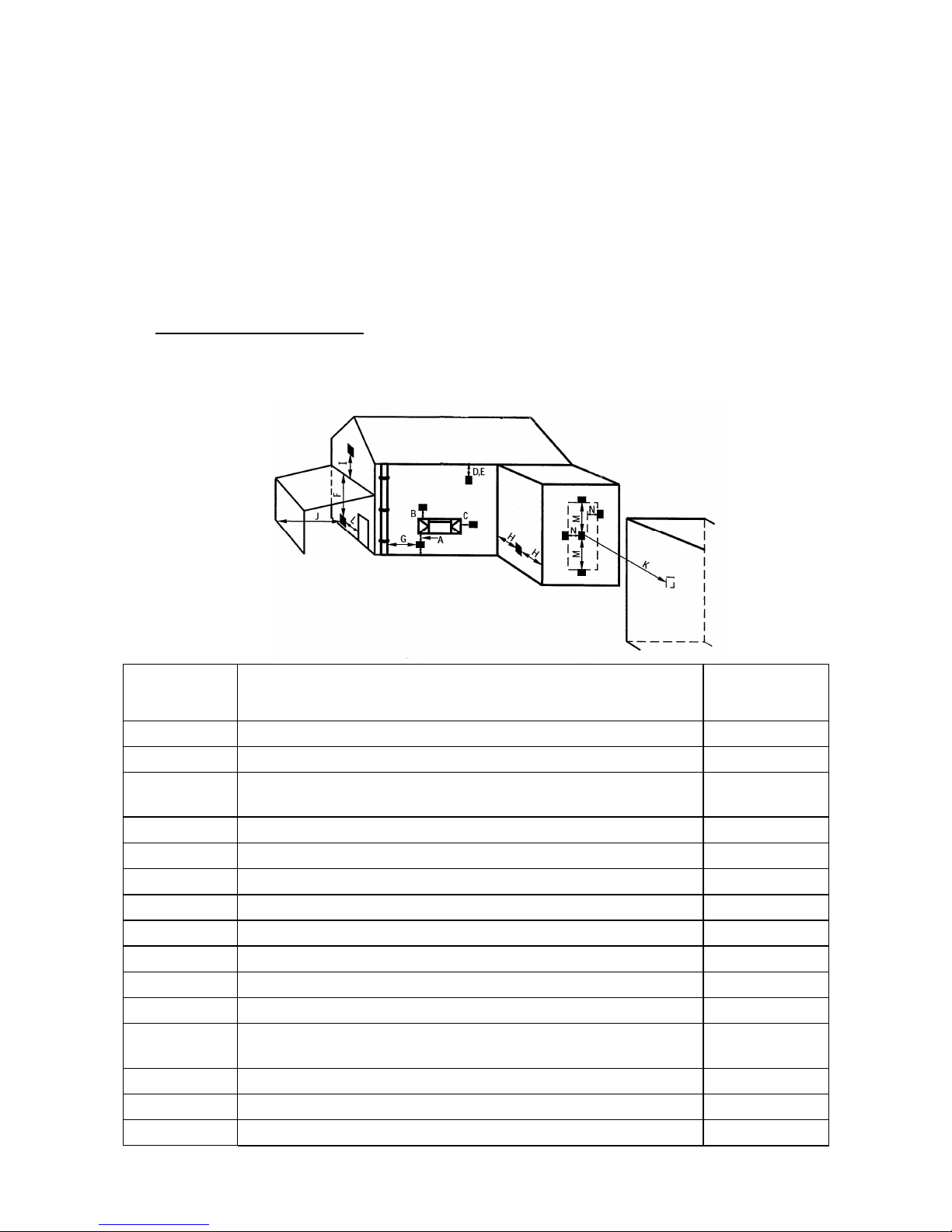
on diagram Below horizontal hinged windows (Eire only) 1000mm
4 Decorative Fascia Panel
This appliance must be installed with the fascia panel set supplied. This panel
allow the passage of air for convection and for the cooling of the control system.
It must be installed as described in these instructions. The fire should never be
left running with this fascia panel dropped down. This will overheat both the
fascia and glass window.
5 Ventilation
This is a room-sealed appliance; therefore, there is no requirement for purpose
made ventilation into the room containing the fire.
6 The appliance is designed for use with natural gas only.
7 The appliance must not be installed in a room containing a bath or shower or in
a private garage.
8 Shelf
If a shelf made of combustible material is to be fixed to the wall above the
appliance a space of at least 150mm must be left between the top of the fascia
and the underside of the shelf.
9 HE HEAR H (Appliances in floor level fireplaces)
Where the appliance is fitted in a floor level builders opening, floor level fireplace
recess or floor level flue box, the hearth shall:
a, Extend through the whole base of the builders opening, fireplace recess or
beneath the flue box.
b, roject at least 275mm in front of the glass window panel.
c, roject at least 150mm beyond each side of the edge of the glass window
panel. or if there is a non-combustible wall within 150mm of glass panel,
up to that wall.
d, Have a thickness of not less than 12mm and a minimum height of 50mm
along its front and side edges.
Hole-in-the-wall installations
Where the appliance is installed in a hole-in-the-wall fireplace, a hearth as
previously detailed for floor level fireplaces shall be fitted on the floor beneath
the hole so as to protect combustible material from radiant heat.
a, If a hearth is not to be used, so as to maintain a minimal and
contemporary styling, the appliance must be installed so that the base of
the appliance is at least 200mm vertically above any carpet or floor
covering.
b, Where no hearth is to be fitted consideration should be given to fixing a
tactile separator to protect young children, the elderly and the infirm. A
tactile separator can be in the form of a fender, kerb, hearth, shelf or
horizontal bar all made from non combustible material and fixed not less
than 50mm & not more than 1000mm above the floor level. It should be
positioned not less than 275mm in front of and 150mm beyond the edge
of the window glass.

6
10 Combustible Walls & imber Framed Dwellings
The appliance may be fitted directly to wall made both from combustible and
non combustible material. If it is to inset into the wall, the inner wall plate
(supplied separately) must be used and a gap of 25mm should be maintained
between the top, rear and sides of the convector box and any combustible
material. These gaps should be filled with mineral wool insulation.
A gap of 50mm must be maintained between the outer flue and any combustible
material including the external wall. This gap must be filled with mineral wool
insulation.
Installations into timber framed dwellings must follow the recommendations of
IGEM/U /7 ‘Gas Installation in Timber Framed Buildings’ available from The
Institute of Gas Engineers and Managers’. The appliance must not be inset
unless provision has been made by the builders with the approval of the
designers of the dwelling.
Fitting
This appliance can be installed either by being fixed directly on to the surface or
it can be inset into the inner leaf of a cavity wall. Before starting the installation
remove the glass door by unscrewing the eight nuts securing the door and place
in a safe place until required.
Undoing the nuts and bolts on the outer flanges of the appliance separate the
heat exchanger from the convector box.
Surface Installation
1 Select a position for the appliance and mark the centre of the flue. This should
be at least 700mm above finished floor level. (This is to give sufficient clearance
to allow the door to drop down). The centre of the glass panel will be 157mm
below this mark (See Figure 2). At this position drill a 152mm diameter hole in
the wall for the flue. Apply white foam tape (supplied) around the edges of the
back of the convector box to form a dust seal between the box and the wall.
2 Thread the outside Terminal plate onto the flue and push the flue into the wall
Figure 2 Figure 3

7
from the outside. Apply mastic to the rear face of the Terminal plate and fix to
the wall using screws and wall plugs. Make sure the plate is fixed the correct
way up. (See Figure 3) Slide the flue further into the wall until the tabs on the
wall plate line up with the holes in the outer flue tube. Temporally fix the tube
to the wall plate with the self tapping screws provided. Use the inner holes as
shown in Figure 4.
3 On the inside wall centre and level the convector box over the protruding flue
pipe. Once level, fix the convector box to the wall with four screws and wall
plugs. The convector box has been designed to ensure an air gap remains
between the wall and the back of the convector box. Consideration should be
given to ensure this gap is achieved and not affected by uneven wall surfaces.
4 From the inside of the convector box measure inwards along the flue 6mm. At
this point draw a line completely around the outer pipe. Unscrew the self
tapping screws securing the outer flue tube to the wall plate and withdraw the
flue assembly. Move the polystyrene support ring inside the flue assembly to a
position near the marked line. Cut the excess flue of at the marked line. De-bur
the cut edges and remove the polystyrene ring.
5 Slide the remaining piece of flue, which should include the terminal, on to the
flue connection on the back of the heat exchanger. Note that the two flue tubes
are not concentric and that the inner tube is positioned towards the top of the
outer tube. Using a 3.5mm diameter drill, drill holes through the holes in the
flue outer ring and into the outer flue tube. Secure in place with self tapping
screws and then cover and seal the joint with the length of aluminium tape
supplied. Thread the fibreglass rope ring sealing gasket on to the flue.
6 The gas supply should be routed from the meter or cylinder to a point
underneath or behind the appliance. There are two grommeted apertures
provided for gas pipe entry in the convector box. From this point route the
supply in 8mm diameter tubing to the combined pressure test point and isolator
fitting. Any exposed pipe within the wall cavity should be wrapped, painted with
bituminous paint or factory sheathed. rior to connecting the burner to the gas
supply it is advisable to blow out the pipe to clear any dirt that may be present
and which could cause a blockage in the control valve or pilot.
7 Lift the heat exchanger and flue assembly and slide the flue assembly through
the hole in the wall until the heat exchanger flange meets the convector box
flange. Fix the heat exchanger to the convector box using the M5 nuts and bolts
supplied. Replace the self tapping screws that secured the flue to the wall plate.
Seal the flue to the wall plate with mastic. Fit the terminal guard centrally over
the terminal using screws and wall plugs.
Figure 4

8
8 If plasterwork requires to be made good, please pay attention to note no. 3 on
page 2 of these instructions
Inset Installation
1 To inset the Limours gas fire, a wall plate, supplied separately, must be used.
2 Select a position for the appliance and the height required from the centre of the
glass panel to the floor. Cut a hole in the inner leaf of the cavity wall to the
dimensions shown in Figure 5. A lintel may be required to support the masonry
over the opening .Any cavity wall insulation should be held back away from the
appliance. Drill a 152mm diameter hole in the outer leaf of the cavity wall for
the flue 157mm above the position of the centre of the glass panel. Ensure that
the centre of the flue is at least 700mm above finished floor level.
3 Thread the outside wall plate onto the flue and push the flue into the wall from
the outside. Apply mastic to the rear face of the wall plate and fix to the wall
using screws and wall plugs. Make sure the plate is fixed the correct way up.
(See Figure 3) Slide the flue further into the wall until the tabs on the wall plate
line up with the holes in the outer flue tube. Temporally fix the tube to the wall
plate with the self tapping screws provided. Use the inner holes as shown in
Figure 4.
4 Temporally screw the convector box to the inner wall plate with four M5 screws.
lace the convector box over the protruding flue pipe and push the box into the
hole already cut in the inner leaf of the cavity wall. Centre the convector box
over the flue pipe. Once level, fix the inner wall plate to the wall with six screws
and wall plugs. Cover the access holes to these screws with the six black plastic
plugs supplied. Once the convector box has been finally secured to the inner
fascia the arrangement can be considered to have sealed the cavity. Any gaps
around the inner fascia and any other gaps can be sealed with mastic.
5 From the inside of the convector box measure along the flue 6mm. At this point
draw a line completely around the outer pipe. Unscrew the self tapping screws
securing the outer flue tube to the wall plate and withdraw the flue assembly.
Move the polystyrene support ring inside the flue assembly to a position near
the marked line. Cut the excess flue of at the marked line. De-bur the cut edges
and remove the polystyrene ring.
6 Slide the remaining piece of flue, which should include the terminal, on to the
flue connection on the back of the heat exchanger. Note that the two flue tubes
are not concentric and that the inner tube is positioned towards the top of the
outer tube. Using a 3.5mm diameter drill, drill holes through the holes in the
Figure 5

9
flue outer ring and into the outer flue tube. Secure in place with self tapping
screws and then cover and seal the joint with the length of aluminium tape
supplied. Thread the fibreglass rope ring sealing gasket on to the flue.
7 The gas supply should be routed from the meter or cylinder to a point
underneath or behind the appliance. There are two grommeted apertures
provided for gas pipe entry in the convector box. From this point route the
supply in 8mm diameter tubing to the combined pressure test point and isolator
fitting. Any exposed pipe within the wall cavity should be wrapped, painted with
bituminous paint or factory sheathed. rior to connecting the burner to the gas
supply it is advisable to blow out the pipe to clear any dirt that may be present
and which could cause a blockage in the control valve or pilot.
8 Remove the four M5 screws holding the convector box to the inner fascia. Lift
the heat exchanger and flue assembly and slide the flue assembly through the
hole in the wall until the heat exchanger flange meets the convector box flange.
Fix the heat exchanger through the convector box flanges to the inner fascia
using the M5 bolts supplied. Replace the self tapping screws that secure the flue
to the wall plate. Seal the flue to the wall plate with mastic. Fit the terminal
guard centrally over the terminal using screws and wall plugs.
9 If plasterwork requires to be made good, please pay attention to note no. 3 on
page 2 of these instructions
Placing of Decorative Refractory Shapes
1 our enough black ceramic granules to fill the space between the front air guide
and the window opening. The granules should finish level with the top of the
window ledge.
2 Two packets of ‘Cotswold Stone’ pieces are supplied with the fire. Open the
smaller packet containing twelve wedge shaped pieces.
3 lace ten of these pieces behind the rear air guide with the longer wedge
pointing downwards. These pieces should be supported by the rear air guide
and by the board at the rear of the fire. See Figure 6.
4 lace the two remaining pieces on top of the brackets at either end of the air
guides.
5 Two pieces from the second packet should be placed at each end of the air
guides. They should rest partly on the front air guide and partly on the black
ceramic granules. See Figure 6.
Figure 6
Figure 7

10
6 lace ten ‘Cotswold Stone’ pieces from the second packet on top of the black
ceramic granules in front of the front air guide as shown in Figure 6.
7 lace the remaining ten ‘Cotswold Stone’ pieces from the second packet across
the air guides pushing each piece down on a location spike formed in the front
air guide. See Figure 7 on previous page.
8 It is important that decorative ‘Cotswold Stone’ pieces are placed as per these
instructions.
Closing the Glass Door
1 lace the glass door in position over the studs on the heat exchanger making
sure the joint in the rope seal lies along the lower edge. Secure in position with
the eight nuts. Tighten evenly.
Installing the Fascia Panel
1 Check that the fascia panel is mounted the correct way up. A TEE is punched in
the top of the inner flanges.
2 Ensure the four M4 screws are mounted in their bushes on the inner flanges.
3 Offer the fascia up to the appliance and slide the heads of the M4 screws
through the cut – outs and into the slots formed in the sides of the convector
box.
4Make sure that the fascia panel slides up and down freely and locks in the top
position.
COMMISSIONING:
1 Before attempting to light the appliance the gas supply must be turned on by
removing the cap from the isolator fitting and unscrewing the plug all the way
out. Replace the cap making sure that the tab engages with the slot in the top of
the plug. Tighten the cap securely. Check all joints with leak detection fluid.
Light the appliance in accordance with the instructions in the lighting section.
2. a. Slide back the battery compartment cover and insert the four AA size
alkaline batteries observing the correct polarities. Replace the cover and place
the battery box on the floor of the convector box.
b. Fit the battery into the handset by removing the access cover in the rear
of the handset and inserting a 9 volt 3 size battery. Connect the battery by
pushing the connector on to the terminals. Make sure the battery is connected
correctly. Replace the access cover.
Briefing the User
1Demonstrate the full operation of the appliance to the customer.
2Inform the customer that all cleaning procedures should be carried out only
when the appliance is cold.
3Leave these instructions with the customer.
4 Advise the importance of having the appliance serviced on an annual basis.

11
USERS GUIDE:
Useful tips & recommendations
Once your fire has been fitted, the following recommendations are made to
ensure you enjoy the best results from your purchase;
1The installation of this appliance must have been carried out by a qualified
installer and in accordance with the requirements of the Gas Safety
(Installation & Use) Regulations
2The glass door and the upper part of the fascia panel are considered to be
working surfaces and as such will become hot when in use. Care should be
exercised when using the controls of the appliance when it is hot. We also
recommend that a fireguard, conforming to BS 8423, be fitted for the protection
of young children, the elderly or infirm.
3When new, any painted surfaces or ceramic components may produce a slight
odour, but this will completely vanish after a few hours of use.
5 The appliance MUS NO be used with the front fascia panel in the dropped
down position or with the glass panel removed. If there is any suspicion of
damage to the glass the appliance must not be used.
6 To obtain the best results from your fire we recommend that it be serviced
annually.
7 These instructions are provided to assist you to operate the fire correctly and
should be kept in a safe place.
8 If you have any reason to suspect a gas leak, turn off the appliance at the
isolating point and contact your installer.
9 Curtains should not be hung above the appliance.
Operation of the fire
1The pilot flame heats the thermocouple probe and allows gas to flow to the
burners. If due to pilot failure, the thermocouple cools, no gas will flow to the
main burner. If the fire is turned off or the flames go out, wait for A LEAS 3
MINU ES before attempting to relight the fire.
2For convenience you will find with the appliance a card giving concise lighting
instructions, please keep this in a safe place.
Opening and Closing the Fascia Panel
CAU ION: ONLY DO HIS WHEN HE FIRE IS COLD
1 To open the fascia panel grip it at each side, lift slightly, pull outwards and
lower.
2 This will allow access to the gas control and to the battery pack-signal receiver
to light the appliance and change the batteries.
3 To close the fascia grip it at each side, lift fully, push forwards and release.
Always grip the fascia at each side where it will be cool and not at the top where
it may be very hot.

12
Lighting the Appliance
1 Lighting: See Figure 8.
a ush in and turn control knob ‘A’ anti-clockwise to the ILOT position.
b Hold knob ‘A’ in for several seconds to purge any air from the system.
c With knob ‘A’ still depressed turn it from the "OFF" position to the " ILOT”
position until the pilot light ignites. Continue to depress the control knob
for a further 10-15 seconds. Release the control knob, the pilot should
stay alight. If the pilot flame goes out, repeat the process, holding down
the control knob for a slightly longer period.
d Depress control knob ‘A’ slightly and turn anti-clockwise to the ON
position. The main burner will not operate until this is done. The main
burner may light depending on the position of Control Knob ‘B’.
e Manual override for remote control
Turn Control Knob ‘B’ anti-clockwise to increase the flame height and
clockwise to decrease the flame height.
2 Extinguishing
a Manual override for remote control
Turn Control Knob ‘B’ fully clockwise. This will turn off the main burner
leaving the pilot burner alight.
b Turn Control Knob ‘B’ to the pilot position. This will also turn off the main
burner leaving the pilot burner alight.
c To extinguish the pilot burner, turn Control Knob ‘B’ to the off position.
Figure 9
Figure 8

13
3 Adjusting the Flame Height using the Remote Control Handset
(Figure 9)
The remote control system fitted to the fire uses ultrasound to transmit
signals between the handset and the fire. It will work best if the grill at the
front of the handset is pointed in the direction of the fire. To prevent
inadvertent ignition of the fire the U button on the handset will not
function unless the SMALL button is held down at the same time. A loud
clicking noise indicates that control knob ‘B’ has reached the end of its
travel.
a Make sure that the pilot burner has been lit and Control Knob ‘A’ has
been turned to the ON position. Also ensure that batteries have been
fitted to the handset and to the battery pack-signal receiver.
b To light the main burner or increase the flame height press and hold the
U button and the SMALL button on the handset. Release when the flame
is at the desired height. The electric motor should be heard moving
Control Knob ‘B’.
c To extinguish the main burner or reduce the flame height press and hold
the DOWN button on the handset. Release when the flame is at the
desired height or has gone out. Once again the electric motor should be
heard moving Control Knob ‘B’.
Cleaning the fire
Ensure that the appliance is cool. Regular dusting with a dry cloth is usually all
that is necessary to keep your appliance looking at its best. From time to time it
may be necessary to clean the steel surface with a slightly damp cloth - do this
while the fire is cool and ensure that no water remains on the appliance surface.
Glass
Let the fire and glass cool completely. Only the outside of the glass can be
cleaned by the user. Wash the glass with warm water, using a soft paper towel
or cloth, rinse and dry thoroughly. Never use abrasive or harsh chemicals to
clean the glass.
For stubborn deposits use a cleaner available from your dealer. Do not allow the
cleaner to touch any brass or stainless steel ornamentation. Ensure that the fire
is cold before undertaking any cleaning. Remember that heat is retained for
some time after the fire is switched off. In normal use your fire requires only
minimal cleaning. Some soot may form on any ceramic pieces placed in the
flames but this is generally harmless unless an excessive amount is deposited.

14
SERVICE AND MAIN ENANCE
BEFORE ANY SERVICING IS CARRIED OU ISOLA E HE APPLIANCE
FROM HE GAS SUPPLY. AF ER REFI ING HE APPLIANCE, CHECK
FOR GAS SOUNDNESS A ALL GAS JOIN S AND ES FOR SPILLAGE.
his product uses fuel effect pieces containing Refractory Ceramic Fibre
(RCF). his material contains man-made vitreous silicate fibres. Excessive
exposure to these materials may cause temporary irritation to eyes, skin
and respiratory tract; consequently, it makes sense to take care when
handling these articles to ensure that the release of dust is kept to a
minimum.
o ensure that the release of fibres from these RCF articles is kept to a
minimum, during installation and servicing we recommend that a HEPA
filtered vacuum cleaner is used to remove any dust accumulated in and
around the appliance before and after working on the appliance. We
recommend that any replaced items are not broken up, but are sealed
within heavy duty polythene bags and clearly labelled as RCF waste. RCF
waste is classed as a stable, non-reactive hazardous waste and may be
disposed of at landfill sites licensed to accept such waste. Protective
clothing is not required when handling these articles but we recommend
that the normal hygiene rules are followed of not smoking, eating or
drinking in the work area and that hands are washed before eating or
drinking.
he appliance should be serviced at least once a year by a registered
engineer and must include changing the oxypilot as a condition of the
guarantee. his is the basic procedure.
1 Remove the fascia panel. See section above headed ‘Installing the Fascia anel’.
2 Unscrew the eight nuts and remove the glass door.
3 The ‘Cotswold Stones’ should be taken off the fire. The centre row should be
carefully lifted off the locating spikes and kept in order so that they can be
returned to their original positions. All the pieces should be shaken to remove
any debris but should only be cleaned if absolutely necessary. This should be
done by gently brushing with a soft brush in a direction away from the person
and any persons nearby. This operation should be performed outside facing
downwind.
4 Remove all the black ceramic granules.
5 Undo the two screws holding the air guide assembly in position a lift it gently
out of the firebox making sure the black ceramic granules remain in their
locating tray. Remove the two screws holding the burner and lift it out of the
appliance.
6 Thoroughly clean the burner ports.
7 The injector can be inspected without removing the control mount platform by
unscrewing it with a small box spanner or pliers.
8 To remove the control mount platform;
a Disconnect the isolator fitting from the gas control.

15
b Remove the 2 screws holding the left hand board bracket. Remove the
bracket and left hand lining board.
c Remove the screw holding the pilot draught shield to the pilot bracket and
lift the shield away.
d Remove the six screws securing the control mount platform to the firebox.
Take care not to damage the gasket.
9 Replace the control mount platform (if it has been removed) and secure with the
six screws previously removed. Replace the pilot shield and the lining board and
bracket. Re-connect the gas supply. lace the burner and air guide assembly in
position ensuring that the mixing tube locates in its hole in the burner mount
over the injector and fix in place with the four screws removed in paragraph 5.
Replace the refractory shapes that were in place on the burner.
10 Replace the black ceramic granules in the tray attached to the air guide. Replace
the ‘Cotswold Stones’ exactly as they were removed making sure that the centre
row are replaced on the spikes using the original piecing in the stones.
11 After cleaning the glass door inside and out replace it and secure with the eight
nuts. Tighten the nuts evenly. Stubborn marks can be removed with steel wool
and detergent.
AF ER REFI ING HE APPLIANCE CHECK FOR GAS SOUNDNESS A ALL GAS JOIN S.
12 Replace the fascia panel.
13 The service record sheet enclosed with these instructions should be complete to
maintain the validity of the warranty.
Battery Replacement
14 HANDSET; The handset is powered by one Alkaline 9volt 3 size battery. If the
fire fails to respond to the handset control check that the red LED on the
handset lights whilst pressing either of the two buttons. If the LED does not
light, the battery in the handset requires renewing. To change the battery in the
handset, remove the battery cover on the underside of the handset, unclip the
battery from its connector and put a new one put in its place. Replace the
cover.
15 BURNER; Open the fascia panel. Lift out the gas control battery pack – signal
receiver from its position on the bottom tray of the convector box. Slide back the
battery compartment cover and replace the four AA size alkaline batteries
observing the correct polarities. Replace the cover and then replace the battery
box in its clip.

16
Spare Parts List
In the event of a part requiring replacement the parts list is as follows
Part Description Part Number
Motorised valve CV-104103
Remote hand control &
Receiver
CV-104413
ilot Burner NG Model CV-104506
Injector NG Model CV-104608

17
B-124830
Issue 2
BFM Europe Limited
rentham Lakes
Stoke on rent, Staffordshire S 4 4 J
el: (01782) 339000 Fax: (01782) 339009
Email: [email protected]m
www.bfm-europe.com
This manual suits for next models
1
Table of contents
Other Kinder Heater manuals