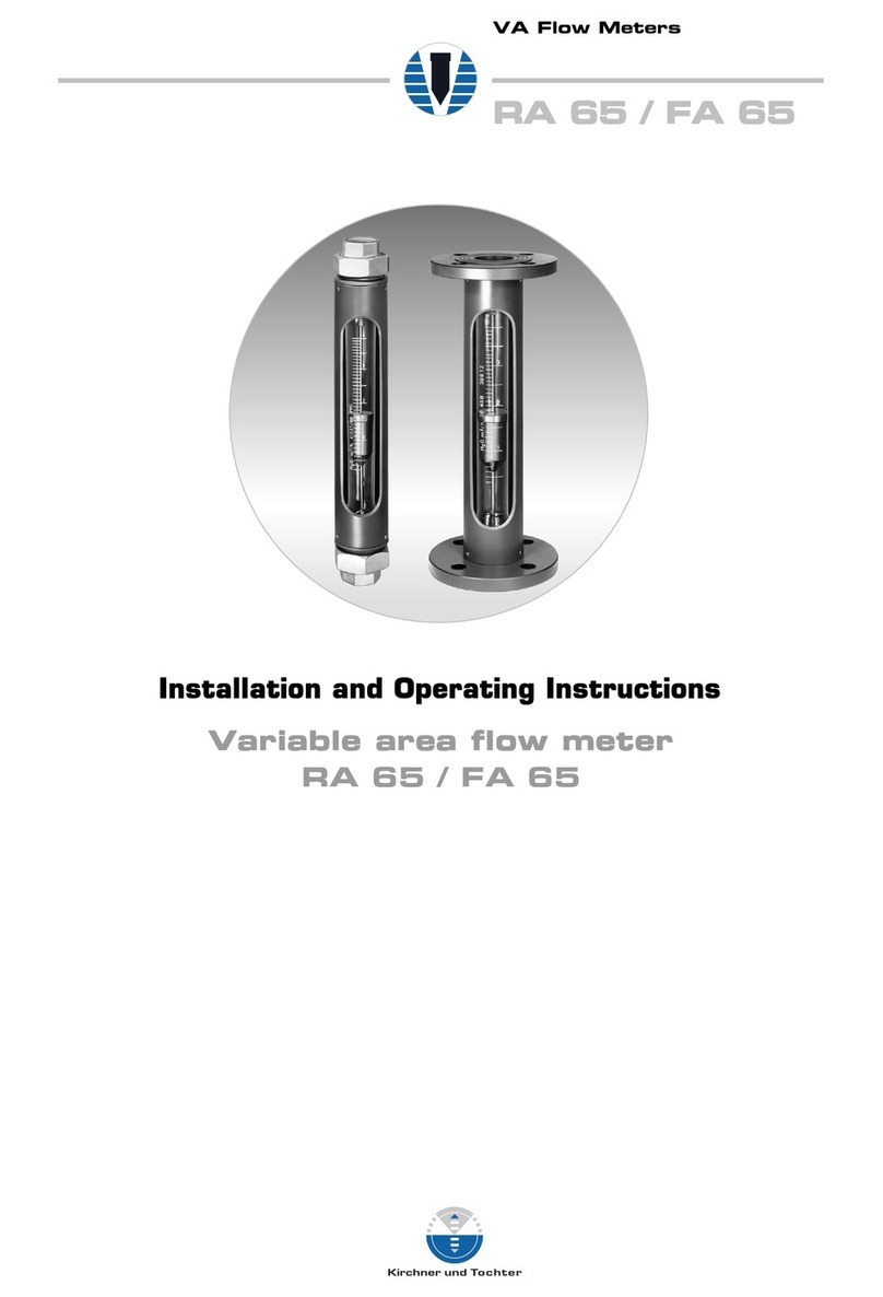
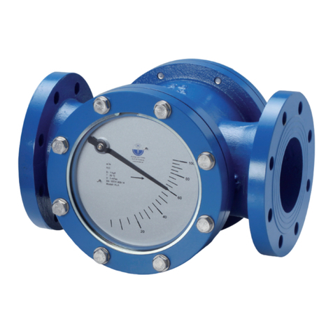
Kirchner und Tochter RA 77 User manual

A. Kirchner & Tochter GmbH Dieselstraße 17 · D-47228 Duisburg
Version 1.1
VA Flow Meters
RA 77 / FA 77
Installation and Operating Instructions
Variable area flow meter
RA 77 / FA 77

A. Kirchner & Tochter GmbH Dieselstraße 17 · D-47228 Duisburg
Version 1.1
VA Flow Meters
RA 77 / FA 77
2
Contents
1. Foreword..................................................................................................................................................................3
2. Safety.........................................................................................................................................................................3
2.1. Symbol and meaning................................................................................................................................3
2.2. General safety directions and exemption from liability............................................................ 3
2.3. Special safety instructions concerning glass devices.............................................................. 3
2.4. Intended use ................................................................................................................................................ 4
2.5. Operator and operating personnel ...................................................................................................4
2.6. Regulations and guidelines ................................................................................................................... 4
2.7. Notice as required by the hazardous materials directive......................................................4
3. Transport and storage......................................................................................................................................4
4. Installation ............................................................................................................................................................... 5
4.1. Preparatory work prior to installation ............................................................................................. 5
4.2. Installing the RA 77.................................................................................................................................. 5
4.3. Installing the FA 77................................................................................................................................... 6
5. Start-up.....................................................................................................................................................................6
6. Readings in operation........................................................................................................................................ 6
7. Limit contacts MSK1, MSK12, MSKW .................................................................................................... 7
7.1. Connection of limit contacts................................................................................................................. 7
7.2. Setting the limit contacts.......................................................................................................................7
8. Maintenance and cleaning of RA77/FA77............................................................................................ 8
8.1. Dismantling and assembly .................................................................................................................... 8
8.2. Replacement of measuring glass...................................................................................................... 8
9. Service ...................................................................................................................................................................... 8
9.1. Disposal.......................................................................................................................................................... 8
10. Technical data .......................................................................................................................................................9
10.1. Dimensions...........................................................................................................................................10
10.2. Technical data of limit contacts..................................................................................................11

10.2.1. Low-Voltage Directive............................................................................................................11

A. Kirchner & Tochter GmbH Dieselstraße 17 · D-47228 Duisburg
Version 1.1
VA Flow Meters
RA 77 / FA 77
3
1. Foreword
These Installation and Operating Instructions are applicable to devices of Series RA
77 and FA 77. Please follow all instructions and information given for installation,
operation, inspection and maintenance. The Instructions form a component part of
the device, and should be kept in an appropriate place accessible to the personnel in
the vicinity of the location. Where various plant components are operated together,
the operating instructions pertaining to the other devices should also be observed.
2. Safety
2.1. Symbol and meaning
Safety notice
This symbol is placed against all directions/information relating to occupational
health and safety in these Installation and Operating Instructions, and draws attention
to danger to life and limb. Such notices should be strictly observed.
2.2. General safety directions and exemption from liability
This document contains basic instructions for the installation, operation, inspection
and maintenance of the variable-area flow meter. Failure to comply with these
instructions can lead to hazardous situations for Man and Beast and also to damage
to property, for which Kirchner und Tochter disclaims all liability.
The Operator is required to rule out potentially hazardous situations through voltage
and released media energy.
2.3. Special safety instructions concerning glass devices
For safety reasons, we recommend fitting a protective shield in front of the
measuring tube when starting up flow meters fitted with glass measuring
tubes. The devices should not be operated where there is a risk of pressure
surges (water hammer)!
To avoid glass breakage, all fitting work between measuring glass and heads inside
the glass should be carried out by twisting and simultaneously pressing after having
wetted the packing rings/gaskets.

A. Kirchner & Tochter GmbH Dieselstraße 17 · D-47228 Duisburg
Version 1.1
VA Flow Meters
RA 77 / FA 77
4
2.4. Intended use
The RA 77/FA 77 Series device is a variable-area flow meter for liquids and gases. It
is designed for installation in vertical pipe runs. Installation in the pipeline should be
carried out solely in accordance with these Instructions. The required version of the
variable-area flowmeter should be selected on the basis of the pipe diameter at the
installation location of the device. The limit values pertaining to the device are
specified in Section 10 and must be complied with. Any modifications or other
alterations to the measuring device may be carried out solely by Kirchner und
Tochter. Installation in horizontal pipe runs is possible using appropriate pipe bends.
The direction of flow must always be from bottom to top. Details of the process
product together with the operating conditions are marked on the measuring glass.
2.5. Operator and operating personnel
Authorized installation, operating, inspection and maintenance personnel should be
suitably qualified for the jobs assigned to them, and should receive appropriate
training and instruction.
2.6. Regulations and guidelines
In addition to the directions given in these Installation and Operating Instructions,
observe the regulations, guidelines and standards, such as DIN EN, and, for specific
applications, the codes of practice issued by DVGW (gas and water) and VdS
(underwriters), or the equivalent national codes, and applicable national accident
prevention regulations.
2.7. Notice as required by the hazardous materials directive
In accordance with the law concerning handling of waste (critical waste) and the
hazardous materials directive (general duty to protect), we would point out that all
flow meters returned to Kirchner und Tochter for repair are required to be free from
any and all hazardous substances (alkaline solutions, acids, solvents, etc.).
Make sure that devices are thoroughly rinsed out to neutralize hazardous
substances.
3. Transport and storage
Always use the original packing for transport, handling and storage. Protect the
device against rough handling, impact, jolts, etc.

A. Kirchner & Tochter GmbH Dieselstraße 17 · D-47228 Duisburg
Version 1.1
VA Flow Meters
RA 77 / FA 77
5
4. Installation
4.1. Preparatory work prior to installation
Preparing the installation location:
1.
Check the pipe run at the installation location. VA flow meters are only suitable
for vertical installation with the direction of flow being from bottom to top. For all
other installation situations appropriate pipe bends need to be fitted in the
existing pipeline to ensure vertical flow through the device from below.
2.
If necessary, support the ends of the pipeline to prevent vibration from being
transmitted to the flow meter.
3.
Clean by blowing out or flushing the pipes leading to the device before connecting
up.
4.
Prepare the installation point with the appropriate pipe (RA 77) or flange
connection (FA 77) before starting to fit the flow meter. Make sure sealing faces
are correctly spaced apart and in true alignment.
5.
On no account should the VA flow meter be used to pull the ends of the pipeline
together (stress-free installation!).
Preparation of the flow meter:
1.
Take the device out of the transport packaging.
2.
Pull the rod used securing the float out of the device (PVC, red or grey).
3.
Check that the float can move freely in the flow meter.
4.
Have ready a suitable adhesive for fixing the inserts to the pipe ends at the
installation location.
4.2. Installing the RA 77
1.
Remove the insert and the union nuts from the device.
2.
Slide the union nuts over the pipe ends at the installation location.
3.
Stick the inserts using a suitable adhesive on to the pipe ends.
4.
Slide the device between the two inserts in the installation location.
5.
On meters with a guided float: 2 additional flat gaskets are included with the
meter. These should be inserted in the inserts before screwing on the union nuts,
or included during assembly. These prevent direct contact between the insert
and the glass.
6.
Screw the union nuts to the device heads and tighten down so that the device is
mounted without stresses in the pipeline. Always tighten the nuts with the aid of a
tool. Fingertight fastening of the union nuts is not sufficient to maintain leak
tightness! For this purpose both union nuts must be held with a belt gripping tool
or other suitable implement. Should the glass have twisted when tightening the
nuts, lightly grease the gaskets at the ends of the glass.

A. Kirchner & Tochter GmbH Dieselstraße 17 · D-47228 Duisburg
Version 1.1
VA Flow Meters
RA 77 / FA 77
6
4.3. Installing the FA 77
1.
Slide the device together with the flat gaskets (not included with the flow meter)
at both ends into the installation point.
2.
Check that the flat gaskets are in alignment and that they do not project into the
pipeline.
3.
Loosely attach the nuts and bolts for the flanged connection.
4.
Tighten down the flanged connection crosswise so that the device is fastened free
of stresses in the pipeline.
5. Start-up
The flow meter must have been properly installed before it is started up.
•Test all device connections.
•To set the flow: pressurize the pipelines by slowing opening the shut-off valves. On
liquid service: carefully evacuate the pipeline.
•Check that all components are leak-tight and, if necessary, tighten down threaded
joints and screw connections.
6. Readings in operation
The flow value is read off from the scale on the glass cone at the top edge of the float.
The measured-value readings are only correct when the operating condition at the
measuring point (flowing medium, operating pressure and temperature) corresponds
to the values marked on the measuring glass. If operating conditions should differ,
the measured value must be corrected with the aid of the general float equation,
which you will find in our technical documents.
You can also do the recalculation with the help of our conversion program given on
our home page: www.kt-web.de, Section “Physical Basics“.

A. Kirchner & Tochter GmbH Dieselstraße 17 · D-47228 Duisburg
Version 1.1
VA Flow Meters
RA 77 / FA 77
7
7. Limit contacts MSK1, MSK12, MSKW
The flow meter can be equipped with limit contacts to provide local indication with
monitoring function.
The limit contacts consist of a limit contact (reed switch) that is switched over by the
magnet integrated in the float. The limit contact is guided in a guide slot in the
protective case and can be adjusted over the full measuring range. The reed
contacts have a bistable characteristic.
Uncontrolled current and voltage peaks can occur in the case of inductive or
capacitive loads, e.g. from contactors or solenoid valves. Such peaks will also occur,
depending on cable geometry, where cables exceed a certain length.
We therefore recommend using an MSR contact protection relay, which is
additionally available. This will increase the contact rating and prevent occurrence of
inductive and capacitive peaks, thus ensuring long service life of the contacts.
Electrical data and limit values are specified in Section 10.2.
7.1. Connection of limit contacts
Electrical connection of the device must be carried out in conformity with the
relevant VDE regulations (or equivalent national standards) and in accordance
with the regulations issued by the local power supply utility.
1.
Disconnect the plant from supply before connecting the limit contact.
2.
Provide a protective circuit for the contacts in keeping with their capacity.
3.
Connect line-side fuse elements matched to consumption.
4.
Connect the cable using the supplied right-angle plug. Assigned are terminals 1
and 2. Earth and terminal 3 are not assigned. The circuit diagram for limit
contacts is shown in the Technical Data, Section 10.2 on page 11.
7.2. Setting the limit contacts
1.
Loosen the lock nut M10 on the neck of the contact.
2.
Slide the contact to the flow value required to be monitored.
3.
Test the switching characteristic by moving the float over and beyond the switching
position.
4.
Retighten the lock nut.

A. Kirchner & Tochter GmbH Dieselstraße 17 · D-47228 Duisburg
Version 1.1
VA Flow Meters
RA 77 / FA 77
8
8. Maintenance and cleaning of RA77/FA77
The flow meter is maintenance-free. Should the glass cone become fouled, the meter
can be removed from the pipeline as follows.
8.1. Dismantling and assembly
Remove the flow meter from the system by detaching the union nuts or the screw
connections and/or pipe unions, as the case may be. After dismantling the upper
head, take the measuring glass out of the device and clean the individual parts.
Reassemble in reverse order. Pay special attention to correct installation of the
appropriate gaskets and the float stop. Before fitting, inspect all gaskets for signs of
damage and replace as and when necessary.
8.2. Replacement of measuring glass
1. To dismantle the device, detach the union nut and take the device out of the
installation point.
2. On devices with non-guided floats, remove the float stop and the float from the old
glass and insert these into the new glass.
3. Fit new gaskets to the device heads.
4. Wet the sealing rings before assembling glass and head.
5. Insert the glass into the case, taking care not to knock the glass against the case.
6. Fasten the device head with the union nut to the case.
7. Align the glass cone so that the inscription can be read through the inspection
window in the case.
8. Reinstall the flow meter.
9. Service
All devices with defects or deficiencies should be sent direct to our repair
department.
To enable our customer service facility to deal with complaints and repairs as quickly
as possible, you are kindly requested to coordinate the return of devices with our
sales department, Tel. +49 2065 9 60 90.
9.1. Disposal
Please help to protect our environment, and dispose of workpieces in conformity with
current regulations or use them for some other practical purpose.

A. Kirchner & Tochter GmbH Dieselstraße 17 · D-47228 Duisburg
Version 1.1
VA Flow Meters
RA 77 / FA 77
9
10. Technical data
Nominal pressure
rating
PVC: PN 10 at 0 to +20°C/max 6 bar
at 40°C
and temperature
resistance of the
device
PP: PN 10 at 0 to +20°C/max 1,5 bar
at 80°C
PVDF: PN 10 at 0 to +20°C/max 5,5 bar
at 80°C
Max. operating pressure
(at 20°Celsius)
Size
9,5
10
19
30
36
43
100
Operat. Press. [bar]
10
10
10
10
8
8
5
Measuring range 1:10
Accuracy class 1,6 acc. to VDE/VDI 3513
Connection RA 77 Union nut and gluing sleeve acc. to
DIN 8063, optionally Thread acc. to
DIN ISO 228 T1
Connection FA 77 Flange PN 10 acc. to DIN 2501
other (ANSI, JIS, ...) on request
Materials
Protective tube PVC-tube with insp. Window, quality PVC-CAW
dark grey
Fittings and
inserts RA 77
PVC, optionally PP, PVDF
Flanges FA 77 PVC, optionally PP, UPGF
Measuring cone Borosilicate glass (Duran)
Shatter protection Plexiglas XT
Seals EPDM, optionally Viton
Floats for fluids PVC rot (lead weighted), optionally
1.4301, 1.4571, PP, PVDF
Floats for gases PVC red, optionally aluminium anodized,
PP, PVDF
With limit switches PVC with magnetic core

A. Kirchner & Tochter GmbH Dieselstraße 17 · D-47228 Duisburg
Version 1.1
VA Flow Meters
RA 77 / FA 77
10
10.1. Dimensions
RA 77
Size Glued d G H S L
DN
9,5 10 16 1/4 1 43 250
15 20 3/8
10 10 16 1/4 1 43 350
15 20 3/8
19 15 20 1/4 1 1/2 60 350
20 25 3/8
25 32 1/2 3/4
30 25 32 1 2 1/4 80 385
32 40 1 1/4
40 50
36 32 40 1 1/4 2 3/4 98 385
40 50 1 1/2
50 63
43 40 50 1 1/2 3 1/2 120 385
50 63 2
65 75
100 50 63 2 4 1/2 140
1)
385
65 75 2 1/2
80 90 3
1)
Union nut: Aluminium hexagonal
FA 77
Screws
Size DN d
2
D H L k a Quantity Thread
9,5 10 14 90 1 284 60 29 4 M 12
15 14 95 288 65 34 4 M 12
10 10 14 90 1 384 60 29 4 M 12
15 14 95 388 65 34 4 M 12
19 15 14 95 1 1/2 388 65 34 4 M 12
20 14 105 394 75 41 4 M 12
25 14 115 400 85 50 4 M 12
30 25 14 115 2 1/4 435 85 50 4 M 12
32 18 140 443 100 61 4 M 16
40 18 150 453 110 73 4 M 16
36 32 18 140 2 3/4 443 100 61 4 M 16
40 18 150 453 110 73 4 M 16
50 18 165 467 125 90 4 M 16
43 40 18 150 3 1/2 453 110 73 4 M 16
50 18 165 467 125 90 4 M 16
65 18 185 479 145 106 4 M 16
100 50 18 165 4 1/2 467 125 90 4 M 16
65 18 185 479 145 106 4 M 16
80 18 200 497 160 125 8 M 16

A. Kirchner & Tochter GmbH Dieselstraße 17 · D-47228 Duisburg
Version 1.1
VA Flow Meters
RA 77 / FA 77
11
10.2. Technical data of limit contacts
Design MSK1 MSK12
Voltage switched 50VAC/75VDC 50VAC/75VDC
Current switched 0,5A 0,5A
Contact rating 10W/VA 10W/VA
Dielectric strength 230VAC/400VDC 230VAC/400VDC
Temperature range -20 bis +90°C -20 bis +90°C
Switching function normally closed contact normally open contact
Design MSKW
Voltage switched 50VAC/75VDC
Current switched 0,5A
Contact rating 5W/VA
Dielectric strength 110VAC/200VDC
Temperature range -20 bis +90°C
Switching function change over contact
1)
The deciding factor is the thermal endurance of the flow meter!
Connection via right angle plug (number of contacts 3 +PE) according to
DIN 46350 Form A and cable gland M16 (IP65)
10.2.1. Low-Voltage Directive
Above 50 V AC/75 V DC, contacts are subject to the EC Low-Voltage Directive.
The user is required to verify their use accordingly.

A. Kirchner & Tochter GmbH Dieselstraße 17 · D-47228 Duisburg
Version 1.1
VA Flow Meters
RA 77 / FA 77
12
The equipment from Kirchner und Tochter
has been tested in compliance with the
applicable CE-regulations of the European
Community. The respective declaration of
conformity is available on request.
The Kirchner und Tochter QM-System will be
certified in accordance with DIN-EN-ISO
9001:2000. The quality is systematically
adapted to the increasing demands.
This manual suits for next models
1
Table of contents
Other Kirchner und Tochter Measuring Instrument manuals

Kirchner und Tochter
Kirchner und Tochter KFS Series User manual

Kirchner und Tochter
Kirchner und Tochter RA 65 User manual

Kirchner und Tochter
Kirchner und Tochter RA 60 User manual

Kirchner und Tochter
Kirchner und Tochter RA 60 User manual

Kirchner und Tochter
Kirchner und Tochter SMB Series User manual

Kirchner und Tochter
Kirchner und Tochter SGK 1-3 User manual

Kirchner und Tochter
Kirchner und Tochter RA 65 User manual

Kirchner und Tochter
Kirchner und Tochter KLA User manual