Kirchner und Tochter KLA User manual

Version 3.1
Dieselstraße 17 · D-47228 Duisburg
Internet: www.kt-ow.de · e-mail: info@kt-ow.de
A. Kirchner & Tochter GmbH
Fon: +49 2065 9609-0 · Fax: +49 2065 9609-22
Assembly and operating Instructions
FLAP-type Flow Meter
KLA
KLA-GS
KLA-V4A
KLA-IK
KLA-IKS
KLA-EM

Version 3.1
Dieselstraße 17 · D-47228 Duisburg
Internet: www.kt-ow.de · e-mail: info@kt-ow.de
A. Kirchner & Tochter GmbH
Fon: +49 2065 9609-0 · Fax: +49 2065 9609-22
-2-
Contents
1 Foreword ................................................................................................................3
2 Safety .....................................................................................................................3
2.1 Symbol and meaning ....................................................................................3
2.2 General safety directions and exemption from liability..................................3
2.3 Intended use .................................................................................................4
2.4 Special safety instructions concerning glass devices ...................................4
2.5 Information for Operator and operating personnel ........................................4
2.6 Regulations and guidelines ...........................................................................4
2.7 Notice as required by the hazardous materials directive ..............................5
3 Transport and storage ............................................................................................5
4 Installation ..............................................................................................................6
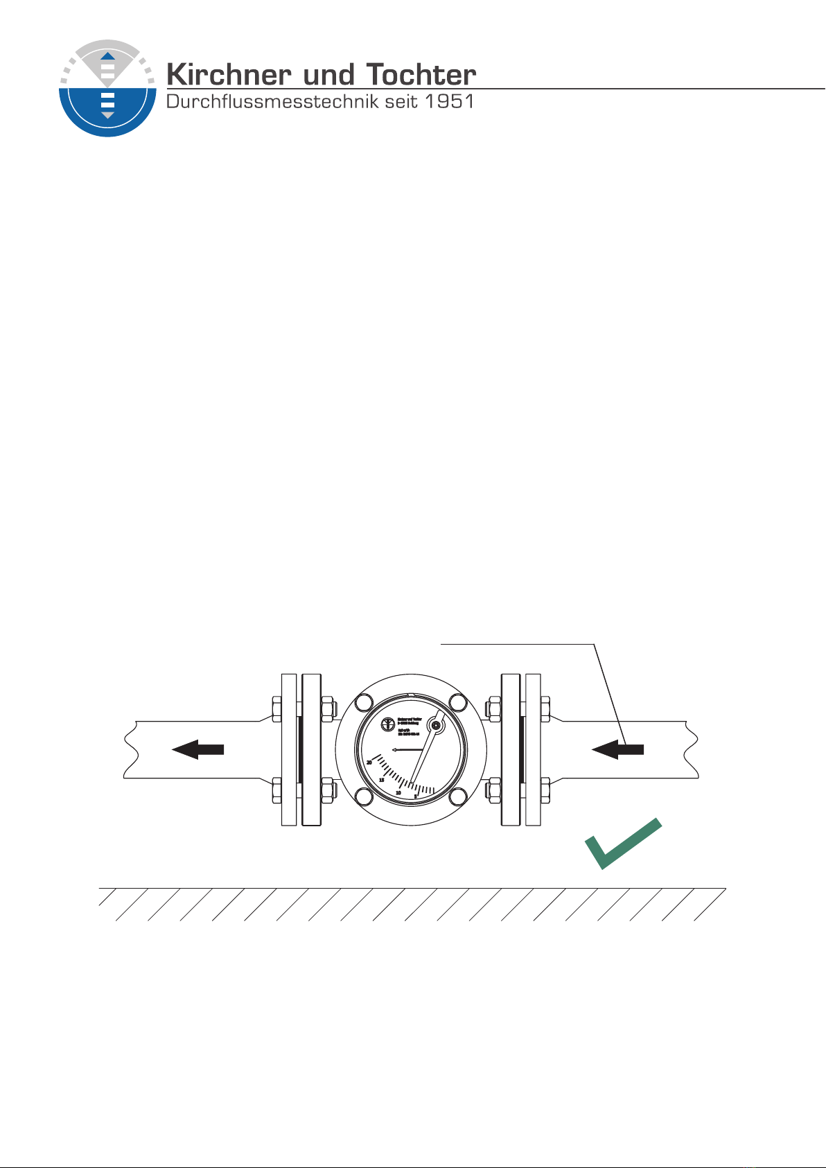
4.1 Mounting position KLA .................................................................................6
4.2 Installation KLA .............................................................................................7
5 Start-up ..................................................................................................................8
6 Readings in operation ............................................................................................8
7 Limit switches .........................................................................................................9
7.1 Connection of limit switches .........................................................................9
7.2 Setting the limit switches ............................................................................10
7.2.1 Preparation.....................................................................................10
7.2.2 Adjusting the limit switches ............................................................10
7.2.3 Adjusting the switching function .....................................................10
7.2.4 Installation of the polycarbonate protective screen ........................11
7.3 Replacing the limit switch............................................................................11
8 Analogue output EM .............................................................................................12
8.1 Functional principle .....................................................................................12
8.2 Connection ..................................................................................................12
9 Maintenance and cleaning of the low meter .........................................................13
10 Service .................................................................................................................13
10.1 Disposal ......................................................................................................13
11 Technical data ......................................................................................................14
11.1 Materials .....................................................................................................15
11.2 Measuring ranges .......................................................................................16
11.3 Dimensions and weights .............................................................................17
11.3.1 Flange connection acc. EN 1092-1 PN10 ......................................17
11.3.2 Flange connection acc. ASME B16.5 class 150lbs ........................18
11.4 Type series .................................................................................................19
11.5 Technical data of limit switches ..................................................................19
11.6 Analogue output EM ...................................................................................21

-3-
Version 3.1
Dieselstraße 17 · D-47228 Duisburg
Internet: www.kt-ow.de · e-mail: info@kt-ow.de
A. Kirchner & Tochter GmbH
Fon: +49 2065 9609-0 · Fax: +49 2065 9609-22
1 Foreword
These Installation and Operating Instructions are applicable to devices
of series KLA. Please follow all instructions and information given for
installation, operation, inspection and maintenance. The Instructions form
a component part of the device and should be kept in an appropriate place
accessible to the personnel in the vicinity of the location. Where various plant
components are operated together, the operating instructions pertaining to
the other devices should also be observed.
2 Safety
2.1 Symbol and meaning
2.2 General safety directions and exemption from liability
Safety notice
This symbol is placed against all directions/information relating to
occupational health and safety in these Installation and Operating
Instructions and draws attention to danger to life and limb. Such notices
should be strictly observed.
This document contains basic instructions for the installation, operation,
inspection and maintenance of the variable area ow meter. Non-observance
of these directions can lead to hazardous situations for man and beast and
also to damage to property, for which Kirchner und Tochter disclaims all
liability.
The operator is required to rule out potentially hazardous situations through
voltage and released media energy.

Version 3.1
Dieselstraße 17 · D-47228 Duisburg
Internet: www.kt-ow.de · e-mail: info@kt-ow.de
A. Kirchner & Tochter GmbH
Fon: +49 2065 9609-0 · Fax: +49 2065 9609-22
-4-
2.3 Intended use
The KLA Series device is a ap-type VA ow meter for uids. It is designed
for installation in horizontal or vertical pipe runs. In vertical pipe runs, ow
through the device must be from below. Installation in the pipeline may only
be carried out in accordance with these Instructions. Select the version of the
ap-type VA ow meter on the basis of the pipe diameter at the installation
location of the device. The limit values for the device are specied in chapter
11 and must be complied with. Any modications or other changes made
to the measuring device may be carried out solely by Kirchner und Tochter.
Details pertaining to the uid product and operating conditions are noted on
the scale.
2.4 Special safety instructions concerning glass devices
For safety reasons, we recommend that owmeters with glass
housings be put into operation with a protective shield. The devices
must not be operated under pressure surges!
2.5 Information for Operator and operating personnel
2.6 Regulations and guidelines
In addition to the directions given in these Installation and Operating
Instructions, observe the regulations, guidelines and standards, such as
DIN EN and for specic applications, the codes of practice issued by DVGW
(gas and water) and VdS (underwriters) or the equivalent national codes and
applicable national accident prevention regulations.
Authorized installation, operating, inspection and maintenance personnel
should be suitably qualied for the jobs assigned to them and should receive
appropriate training and instruction. All persons charged with assembly,
mounting, operation, inspection and maintenance duties must have read
and understood the operating instructions. Gaskets in contact with the uid
product must be replaced after all maintenance and repair work.

-5-
Version 3.1
Dieselstraße 17 · D-47228 Duisburg
Internet: www.kt-ow.de · e-mail: info@kt-ow.de
A. Kirchner & Tochter GmbH
Fon: +49 2065 9609-0 · Fax: +49 2065 9609-22
2.7 Notice as required by the hazardous materials directive
3 Transport and storage
Always use the original packing for transport, handling and storage. Protect
the device against rough handling, coarse impact, jolts etc.
In accordance with the law concerning handling of waste (critical waste)
and the hazardous materials directive (general duty to protect), we would
point out that all ow meters returned to Kirchner und Tochter for repair
are required to be free from any and all hazardous substances (alkaline
solutions, acids, solvents etc.).
Make sure that devices are thoroughly rinsed out to neutralize
hazardous substances.

Version 3.1
Dieselstraße 17 · D-47228 Duisburg
Internet: www.kt-ow.de · e-mail: info@kt-ow.de
A. Kirchner & Tochter GmbH
Fon: +49 2065 9609-0 · Fax: +49 2065 9609-22
-6-
4 Installation
Flap-type ow meters are suitable for installation in either vertical or
horizontal pipe runs. In vertical pipe runs, ow must be from bottom to top.
Make sure the pipes are correctly spaced and in true alignment at the
installation location for the ow meter. For connection of the KLA device, t
the open ends of the pipeline at the installation point with anges appropriate
to the ow meter.
Straight unimpeded pipe runs upstream and downstream of the meter’s
installation location should have a length equal to a minimum of 2 x DN.
4.1 Mounting position KLA
When the KLA is mounted horizontally with left/right or right/left ow direction,
make sure that the device is installed with the scale facing the front.
This position will ensure that the device functions properly (see Figure 1).
The device cannot function if it is installed with the scale facing upwards or
downwards (see Figure 2).
CORRECT:
The scale faces in front.
Figure 1
Flow direction
dependent on order

-7-
Version 3.1
Dieselstraße 17 · D-47228 Duisburg
Internet: www.kt-ow.de · e-mail: info@kt-ow.de
A. Kirchner & Tochter GmbH
Fon: +49 2065 9609-0 · Fax: +49 2065 9609-22
WRONG:
The scale faces upwards/downwards.
Figure 2
4.2 Installation KLA
For mounting, provide the connection anges of the KLA with suitable at
gaskets. The gaskets are not included with the ow meter.
Before installing, remove the transport lock from inside the device and t the
open pipe ends with appropriate connecting anges. Make sure the pipes are
in true alignment and the sealing faces spaced correctly. Install the device
in the direction of ow indicated by the arrow on the scale such that it is free
from stresses. Use gaskets made of rubber, PVC or Teon.

Version 3.1
Dieselstraße 17 · D-47228 Duisburg
Internet: www.kt-ow.de · e-mail: info@kt-ow.de
A. Kirchner & Tochter GmbH
Fon: +49 2065 9609-0 · Fax: +49 2065 9609-22
-8-
5 Start-up
6 Readings in operation
On the standard device, values are read o at the pointer on the
aluminium scale. On the KLA GS version, the ow rate is indicated directly
by the ap. At the front and rear, the ow meter features in each case a pane
of hard glass. The ow rate is read o from a scale attached to the front hard
glass pane on a level with the top edge of the KLA ap.
Measured values are correct only when the operating condition at the
measuring point (owing medium, operating pressure and temperature)
corresponds to the operating state data marked on the scale
The device must be properly installed before it is started up.
1. Check all device connections.
2. To set the ow: pressurize the pipelines by slowly opening the shut-o
valves. On liquid service: carefully vent the pipeline.
3. Check the leak-tightness of all components and if necessary, tighten
down threaded joints or screw connections.

-9-
Version 3.1
Dieselstraße 17 · D-47228 Duisburg
Internet: www.kt-ow.de · e-mail: info@kt-ow.de
A. Kirchner & Tochter GmbH
Fon: +49 2065 9609-0 · Fax: +49 2065 9609-22
7 Limit switches
The ow meter can be equipped with limit switches with preset switching
point to provide local indication with monitoring function. The switches have a
bistable characteristic.
The following devices are equipped with limit switches:
KLA Standard-IK with BI1-HS540-Y1 - 2-Wire, NAMUR
KLA Standard-IKS with BI1-HS540-AP6X - 3-Wire, PNP, NO
KLA V4A-IK with BI1-HS540-Y1 - 2-Wire, NAMUR
KLA V4A-IKS with BI1-HS540-AP6X - 3-Wire, PNP, NO
Uncontrolled current and voltage peaks can occur in the case of inductive
or capacitive loads, e.g. from contactors or solenoid valves. Such peaks will
also occur, depending on cable geometry, when cables exceed a certain
length. We therefore recommend using an MSR contact protection relay,
which can be additionally supplied. This will increase the contact rating and
prevent the occurrence of inductive and capacitive peaks, thus ensuring long
service life of the contacts.
Electrical data and limit values are specied in chapter 11.
7.1 Connection of limit switches
4. The connection is established via the two or three cable ends of the limit
switch.
Electrical connection of the device must be carried out in conformity
with the relevant VDE regulations (or equivalent national standards)
and in accordance with the regulations issued by the local power
supply utility.
1. Disconnect the plant from supply before connecting the limit switch.
2. Provide a protective circuit for the switches in keeping with their capacity.
3. Connect line-side fuse elements matched to consumption.

Version 3.1
Dieselstraße 17 · D-47228 Duisburg
Internet: www.kt-ow.de · e-mail: info@kt-ow.de
A. Kirchner & Tochter GmbH
Fon: +49 2065 9609-0 · Fax: +49 2065 9609-22
-10-
7.2 Setting the limit switches
The KLA is adjusted during factory assembly to the customer-specic
switching points.
If a new setting is required, the switching point can be changed by moving
the pointer vane.
The switching function can be reversed by specifying whether the pointer
vane rst enters or rst exits the slot sensor.
7.2.1 Preparation
In order to make the settings, the polycarbonate screen has to be removed.
1. First Remove the tensioning ring out of its groove, using a small
screwdriver.
2. Take the polycarbonate screen from the ring.
3. Make sure that the O-ring located under the screen is not lost! It secures
the scale space from dust and dirt ingress.
You have now access to the limit switches and the pointer vane.
7.2.2 Adjusting the limit switches
1. Manually move the pointer to the ow value at which the switching
operation is to be performed. Fix the pointer and make sure that the
pointer cannot move during the adjustment procedure.
2. Depending on the desired switching function of the limit switch and the
ow direction, turn the pointer vane until one of its edges reaches the
switching contact.
3. Check the switching point by moving the pointer through it manually.
7.2.3 Adjusting the switching function
The switching function of the contact can be set, depending on whether the
pointer vane moves into the contact or moves out of him, when reaching the
switching point.
2-wire BI1-HS540-Y1:
Pointer vane detected → Current consumption ≤ 1.2 mA
Pointer vane not detected → Current consumption ≥ 2.1 mA
3-wire BI1-HS540-AP6X:
Pointer vane detected → Signal output closed
Pointer vane not detected → Signal output open

-11-
Version 3.1
Dieselstraße 17 · D-47228 Duisburg
Internet: www.kt-ow.de · e-mail: info@kt-ow.de
A. Kirchner & Tochter GmbH
Fon: +49 2065 9609-0 · Fax: +49 2065 9609-22
7.2.4 Installation of the polycarbonate protective screen
After successful adjustment of the limit switches, you must install the
polycarbonate screen again.
1. Insert the O-ring into the corresponding groove.
2. Put the polycarbonate screen back in. Make sure that the O-ring does
not slip out of its groove.
3. Put the tensioning ring carefully into the corresponding groove.
7.3 Replacing the limit switch
If you need to replace the limit switch, please state the serial number of
your device when ordering. If necessary, put your system or machine in a
condition where the activation of the limit switch cannot cause any problems
or damage.
1. If necessary, clean the device in the area of the cable outlet to prevent
dirt from entering the scale chamber.
2. Loosen the M4 cylinder head screw with a size 2.5 Allen key.
3. Carefully pull the complete limit switch unit out of the owmeter.
If necessary, use the M4 ejector thread.
4. Insert the new unit.
Take care not to knock against the pointer vane!
5. Insert the M4 cylinder head screw into the countersunk hole and tighten
it.
6. Connect the connection cables to your control/evaluation system.

Version 3.1
Dieselstraße 17 · D-47228 Duisburg
Internet: www.kt-ow.de · e-mail: info@kt-ow.de
A. Kirchner & Tochter GmbH
Fon: +49 2065 9609-0 · Fax: +49 2065 9609-22
-12-
8 Analogue output EM
The angular position encoder
EM is a 3-wire sensor, which
delivers an output signal (4 ... 20 mA)
proportional to the angular position of the
pointer. This signal, for example, can be
used to realize a remote display.
A linearization is possible at up to
14 points. Furthermore various input
and output lters ensure operation in
industrial environments.
The following devices are equipped
with limit an analogue output:
KLA Standard-EM with WPG NG100-L
KLA-V4A-EM with WPG NG100-L
8.1 Functional principle
The direction of the magnetic eld of a rotatable mounted
magnet, which is moved by a fork, is detected by a Hall-sensor,
processed by a digital processor and converted to an output
signal of 4 ... 20 mA.
8.2 Connection
Pin 1 (+Ub) and 3 (-Ub) are connected to the power supply 12 ... 36 VDC
(direct current). Pin 2 (Iout) is the analogue output.
The current is measured between pin 2 (Iout) and pin 3 (-Ub).
Further information can be found in Section 11.6.

-13-
Version 3.1
Dieselstraße 17 · D-47228 Duisburg
Internet: www.kt-ow.de · e-mail: info@kt-ow.de
A. Kirchner & Tochter GmbH
Fon: +49 2065 9609-0 · Fax: +49 2065 9609-22
9 Maintenance and cleaning of the low meter
CAUTION
Material damage or health hazards resulting may arise from uid
leakage. Kirchner und Tochter does not assume any liability for
improper use. Before you start maintenance/cleaning, make sure that
the medium line is shut o resp. emptied.
The KLA can be opened from the back. Undo the fastening screws on the
rear cover and take the cover o. Remove any dirt and deposits that may
have accumulated in the casing and on the ap. The shaft of the ap runs
on pivot bearings. Should these have too much play, the device can also be
opened from the front. Detach the lock nuts and retighten the bearing screws.
Then retighten the lock nuts. The ap must be positioned so close to the front
plate that, without the seal, it just slightly rubs against this plate. If the seal is
then re-inserted before nal assembly, the ap will move freely. The pointer
must be able to move freely across the aluminium plate. Be sure to replace
the cover to close the device tightly.
10 Service
10.1 Disposal
All devices with defects or deciencies should be sent directly to our repair
department. In the service area of the Kirchner und Tochter homepage
(www.kt-ow.de) you will nd the declaration of decontamination as download
and more information about returns.
To avoid risks to our employees and the environment, we can only process
devices, for which we get a declaration of decontamination certifying that
they are safe due to legal regulations. For questions, please contact our
sales department, Tel. +49 2065-96090.
Please help to protect our environment and dispose workpieces in conformity
with current regulations resp. continue using them.

Version 3.1
Dieselstraße 17 · D-47228 Duisburg
Internet: www.kt-ow.de · e-mail: info@kt-ow.de
A. Kirchner & Tochter GmbH
Fon: +49 2065 9609-0 · Fax: +49 2065 9609-22
-14-
11 Technical data
Connection Flange connection acc. EN 1092-1 PN10
optionally: ANSI B16.5 150 lbs
Pressure ranges PN 10 (standard)
in special design PN 6
Connection sizes DN 15 – 200 / ½“ – 8“
Installation length see table section 11.3
Corrosion protection powder coating, kiln-dried, trafc blue (RAL 5017)
Corrosion class C3
Rubber lining NR-isoprene quality
Temperature resistance 1) 2)
standard max. 100 °C
with rubber lining max. 90 °C
special design up to 150 °C
Ambient temperature 2) max. 90 °C
Measuring range usu. 1:10
Uncertainty of measurement 5 % FS
Viewing window Soda lime glass, optionally Borosilicate glass
Degree of protection in conformity with IP 54, switches: IP 53
1) The medium to be measured must not freeze.
2) KLA-IK resp. KLA-IKS max. 70°C
other connection geometries on request

-15-
Version 3.1
Dieselstraße 17 · D-47228 Duisburg
Internet: www.kt-ow.de · e-mail: info@kt-ow.de
A. Kirchner & Tochter GmbH
Fon: +49 2065 9609-0 · Fax: +49 2065 9609-22
11.1 Materials
Type/Fitting ap bearing disc blind ange/ring seal DN
KLA
Gray cast iron
EN-GJL-200 1.4571 1.4571 1.4571 EN-GJL-200/S355 NBR 15 – 150
Steel S355, welded 1.4571 1.4571 1.4571 S355 NBR 200
KLA-V4A
Stainless steel
1.4571, welded 1.4571 1.4571 1.4571 1.4571 FKM 25 – 100
KLA-GS
Gray cast iron
EN-GJL-200 1.4571 1.4571 Soda lime
glass1) S355 NBR 15 – 25
KLA-GS-V4A
Stainless steel
1.4571, welded 1.4571 1.4571 Borosilicate
glass 1.4571 FKM 25 – 100
KLA rubber lined design
Gray cast iron
EN-GJL-200
rubber lined
1.4571 1.4571 1.4571 EN-GJL-200/S355
rubber lined Sil-C8200 32 – 150
Gray cast iron
EN-GJL-200
rubber lined
Hastelloy
C4
Hastelloy
C4
1.4571 –
PTFE
EN-GJL-200/S355
rubber lined Sil-C8200 32 – 150
Gray cast iron
EN-GJL-200
rubber lined
PTFE Hastelloy
C4
1.4571 –
PTFE
EN-GJL-200/S355
rubber lined Sil-C8200 80 – 150
Gray cast iron
EN-GJL-200
rubber lined
PTFE PTFE 1.4571 –
PTFE
EN-GJL-200 / S355
rubber lined Sil-C8200 80 – 150
We quote other designs on request:
- gaskets, rubber lining (also with the approval for drinking water)
- cast bronze (CuSn)
3) optionally: borosilicate glass

Version 3.1
Dieselstraße 17 · D-47228 Duisburg
Internet: www.kt-ow.de · e-mail: info@kt-ow.de
A. Kirchner & Tochter GmbH
Fon: +49 2065 9609-0 · Fax: +49 2065 9609-22
-16-
11.2 Measuring ranges
DN measuring range H2O
horizontal ow
measuring range H2O
vertical ow
max. operating pressure [bar]
standard version KLA-GS
15 0,2
0,3
–
–
1
6
m³/h
m³/h
0,2
1
–
–
1,5
6,5
m³/h
m³/h 10 10
20 0,2
0,3
–
–
1
6
m³/h
m³/h
0,2
1
–
–
1,5
6,5
m³/h
m³/h 10 10
25 0,2
0,3
–
–
1
6
m³/h
m³/h
0,2
1
–
–
1,5
6,5
m³/h
m³/h 10 10
32
0,5
0,7
3
–
–
–
4
7
30
m³/h
m³/h
m³/h
0,5
0,6
2,5
–
–
–
4
6
25
m³/h
m³/h
m³/h
10 9
40
0,5
0,7
3
–
–
–
4
7
30
m³/h
m³/h
m³/h
0,5
0,6
2,5
–
–
–
4
6
25
m³/h
m³/h
m³/h
10 9
50
0,5
0,7
3
–
–
–
4
7
30
m³/h
m³/h
m³/h
0,5
0,6
2,5
–
–
–
4
6
25
m³/h
m³/h
m³/h
10 9
65
1
2
4
–
–
–
8
15
50
m³/h
m³/h
m³/h
2
4
5
–
–
–
15
15
40
m³/h
m³/h
m³/h
10 10
80
1
2
7
–
–
–
10
20
70
m³/h
m³/h
m³/h
2
3
5
–
–
–
10
20
50
m³/h
m³/h
m³/h
10 10
100 1,5
12
–
–
15
120
m³/h
m³/h
1,5
10
–
–
15
100
m³/h
m³/h 10 10
125 2
14
–
–
20
140
m³/h
m³/h
2
12
–
–
20
120
m³/h
m³/h 10 7
150
2
5
16
15
–
–
–
–
25
50
160
200
m³/h
m³/h
m³/h
m³/h*
4
10
15
–
–
–
–
25
80
140
m³/h
m³/h
m³/h
m³/h
10 6,5
200 8
25
–
–
80
300
m³/h
m³/h
15
20
–
–
150
300
m³/h
m³/h 10 ---
The table shows the minimum and maximum measuring range, all intermediate measuring ranges
available on request.
Pressure loss 20 – 30 mbar depending on the ow-rate.
* only with glass screen

-17-
Version 3.1
Dieselstraße 17 · D-47228 Duisburg
Internet: www.kt-ow.de · e-mail: info@kt-ow.de
A. Kirchner & Tochter GmbH
Fon: +49 2065 9609-0 · Fax: +49 2065 9609-22
11.3 Dimensions and weights
11.3.1 Flange connection acc. EN 1092-1 PN10
Dimensions S
DN Ø D Ø k Ø d4Ø H LØ D2d2number of
screws
standard /
IK
GS EM weight
[kg]
15 95 65 45 18 170 119 M12 4 145 132 164 8
20 105 75 58 18 170 119 M12 4 145 132 164 8,5
25 115 85 68 18 170 119 Ø 14 4 145 132 164 9
32 140 100 78 21 240 165 Ø 18 4 176 186 195 16
40 150 110 88 21 240 165 Ø 18 4 176 186 195 16
50 165 125 102 21 240 165 Ø 18 4 176 186 195 17
65 185 145 122 21 280 185 Ø 18 4 201 217 220 22
80 200 160 138 22 320 225 Ø 18 8 214 227 233 34
100 220 180 158 24 350 245 Ø 18 8 267 278 286 43
125 250 210 188 25 380 285 Ø 18 8 299 310 318 58
150 285 240 212 25 380 295 Ø 22 8 299 310 318 64
200 340 295 268 27 550 370 Ø 22 8 386 - 405 104
all dimensions in mm

Version 3.1
Dieselstraße 17 · D-47228 Duisburg
Internet: www.kt-ow.de · e-mail: info@kt-ow.de
A. Kirchner & Tochter GmbH
Fon: +49 2065 9609-0 · Fax: +49 2065 9609-22
-18-
11.3.2 Flange connection acc. ASME B16.5 class 150lbs
Dimensions S
NPS Ø DN Ø D Ø k Ø d4Ø H LØ D2d2number
of screws
standard/
IK
GS EM weight
[kg]
½“ 15 90 60,3 34,9 18 170 119 1/2“ * 4 145 132 166 8
¾“ 20 100 69,9 42,9 18 170 119 Ø 15,9 4 145 132 166 8,5
1“ 25 110 79,4 50,8 18 170 119 Ø 15,9 4 145 132 166 9
1 ¼“ 32 115 88,9 63,5 21 240 165 Ø 15,9 4 176 186 197 16
1 ½“ 40 125 98,4 73,0 21 240 165 Ø 15,9 4 176 186 197 16
2“ 50 150 120,7 92,1 21 240 165 Ø 19,1 4 176 186 197 17
2 ½“ 65 180 139,7 104,8 21 280 185 Ø 19,1 4 201 217 222 22
3“ 80 190 152,4 127,0 22 320 225 Ø 19,1 4 214 227 235 34
4“ 100 230 190,5 157,2 24 350 245 Ø 19,1 8 267 278 288 43
5“ 125 255 215,9 185,7 25 380 285 Ø 22,2 8 299 310 320 58
6“ 150 280 241,3 215,9 25 380 295 Ø 22,2 8 299 310 320 64
8“ 200 345 298,5 269,9 27 550 370 Ø 22,2 8 386 - 407 104
alle Maße in mm
* Thread according to customer specication (UNC, UNF, G etc.)

-19-
Version 3.1
Dieselstraße 17 · D-47228 Duisburg
Internet: www.kt-ow.de · e-mail: info@kt-ow.de
A. Kirchner & Tochter GmbH
Fon: +49 2065 9609-0 · Fax: +49 2065 9609-22
11.4 Type series
KLA with magnetically coupled pointer dial
KLA-GS with glass screen
KLA-IK with one inductive switch
KLA-IKS with one electronic switch
KLA-EM angular position encoder with 4 ... 20 mA analogue output
KLA-V4A ↳ made of stainless steel (1.4571)
KLA Ex explosion proof design
KLA-IK Ex ↳with one inductive switch
11.5 Technical data of limit switches
The following devices are equipped with limit switches:
KLA Standard-IK with BI1-HS540-Y1 - 2-Wire, NAMUR
KLA Standard-IKS with BI1-HS540-AP6X - 3-Wire, PNP, NO
KLA V4A-IK with BI1-HS540-Y1 - 2-Wire, NAMUR
KLA V4A-IKS with BI1-HS540-AP6X - 3-Wire, PNP, NO
IK 2-wire (BI1-HS540-Y1)
Features adjustable, bistable
Switching function Normally closed, normally open
Output function Two-wire, NAMUR
Voltage:
NAMUR / other applications max. 8.2 V DC / 8 ... 20 V DC
Power consumption: Pointer ag
not captured / captured ≥ 2,1 mA / ≤ 1,2 mA
Repeatability ≤ 2 % f.s.
Temperature drift ≤ ± 10 %
Hysteresis 1 ... 10 %
Temperature stability -25 ... +70 °C
Approval according to KEMA 02 ATEX 1090X
Identication of the sensor Ex II 2 G Ex ia IIC T6 Gb / II 1 D Ex ia IIIC T95 °C Da
Sil according to IEC 61508 SIL 3 and PL
Degree of protection IP 67
MTTF 6198 years according to SN 29500 (Ed. 99) 40 °C
Electrical connection cord
Cable quality Ø 3 mm, blue, Lif9YYW, PVC, 2 m
Cable cross-section 2 x 0.14 mm²
Circuit diagram BN= brown= +
BU= blue= -

Version 3.1
Dieselstraße 17 · D-47228 Duisburg
Internet: www.kt-ow.de · e-mail: info@kt-ow.de
A. Kirchner & Tochter GmbH
Fon: +49 2065 9609-0 · Fax: +49 2065 9609-22
-20-
IKS 3-wire (BI1-HS540-AP6X)
Features adjustable, bistable
Switching function Normally closed, normally open
Output function Three-wire, PNP
Operating voltage 10 ... 30 V DC
Repeatability ≤ 2 % f.s.
Temperature drift ≤ ± 10 %
Hysteresis 3 ... 15 %
DC Rated operational current ≤ 100 mA
No-load current ≤ 15 mA
Residual current ≤ 0.1 mA
Temperature stability -25 ... +70 °C
Degree of protection IP 67
MTTF 2283 years according to SN 29500 (Ed. 99) 40 °C
Electrical connection cord
Cable quality Ø 3 mm, grey, Lif9Y-11Y, PUR, 2 m
Cable cross-section 3 x 0,14 mm²
Circuit diagram
BN= brown= +
BU= blue= -
BK= black= signal
This manual suits for next models
5
Table of contents
Other Kirchner und Tochter Measuring Instrument manuals

Kirchner und Tochter
Kirchner und Tochter RA 65 User manual

Kirchner und Tochter
Kirchner und Tochter RA 60 User manual

Kirchner und Tochter
Kirchner und Tochter RA 77 User manual

Kirchner und Tochter
Kirchner und Tochter KFS Series User manual

Kirchner und Tochter
Kirchner und Tochter SGK 1-3 User manual

Kirchner und Tochter
Kirchner und Tochter SMB Series User manual

Kirchner und Tochter
Kirchner und Tochter RA 60 User manual

Kirchner und Tochter
Kirchner und Tochter RA 65 User manual