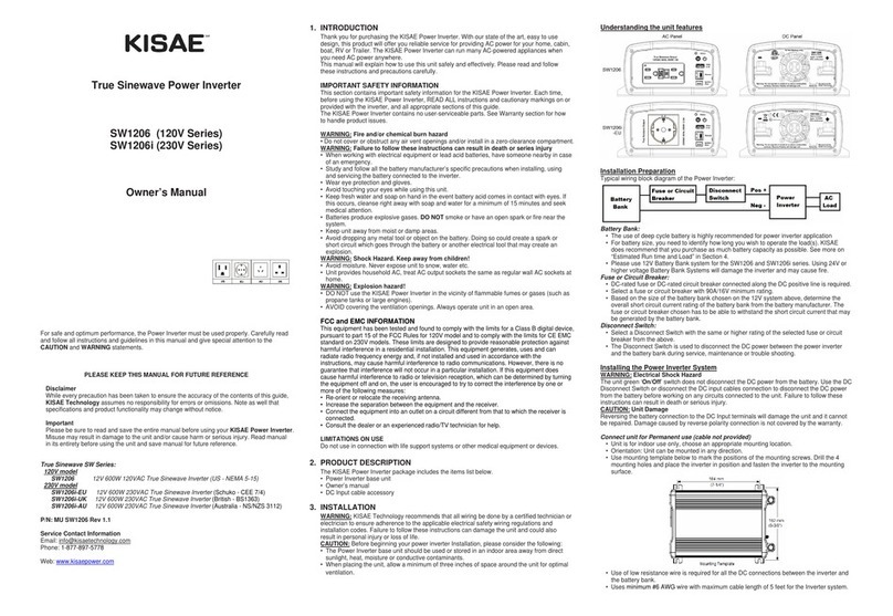
Power Inverter DC Input Connection:
• Connect one end of the negative DC input cable to the Power Inverter DC negative terminal (black).
Connect the other end of the negative DC input cable to the battery negative terminal.
• Make sure the Disconnect Switch is in the OFF position.
• Connect one end of the positive DC input cable to the Power Inverter DC positive terminal (red).
Connect the other end of the positive DC input cable to one of the terminal of the Disconnect Switch.
• Connect a DC input cable between the other terminal of the Disconnect Switch and one side of the
terminal of the fuse holder.
• Connect a DC input cable between the other terminal of the fuse holder and the battery positive
terminal.
• Install the selected fuse to the fuse holder.
• Turn Disconnect Switch to ON position.
Connect unit with optional accessories using the Lighter plug cable:
CAUTION:
Due to the limitations of the 12V lighter plug socket in vehicles, the unit should be used with
the DC cable with lighter plug only to supply AC power to products that require 150W (120VAC/1.3 Aor
230V 0.65A) or less. If the appliance requires more than 150W, use the optional DC cable clips for battery
connection.
• Attach the red ring-type connector to the positive (+) DC terminal (red) on the power inverter and
connect the black ring type connector to the negative (-) DC terminal (black) on the Power inverter.
• Tighten the nut on each DC terminal.
• Insert the light plug of this cable to the fused 12V lighter plug socket.
• Unit is ready for use.
Connect unit with optional accessories using the Battery clips cable:
CAUTION:
Please be sure all the connections are tight before the use of the unit.
• Attach the red ring-type connector to the positive (+) DC terminal (red) on the power inverter and
connect the black ring type connector to the negative (-) DC terminal (black) on the Power inverter.
• Attach the negative (black) clip to the negative (-) battery terminal.
• Attach the positive (red) clip to the fuse or circuitry breaker of the 12V battery bank as indicated on
‘Typical Wiring block diagram of the Power Inverter’ .
• Unit is ready for use.
Test the Power Inverter:
• Turn unit on by using the On/Off button on the unit.The ‘Power’ light turns on indicating the KISAE
Power Inverter is ON. AC output is now available.
• Plug in a small AC load like a 25W table lamp or small appliance to theAC socket to verifyAC is
available.
• The unit is successfully installed and functioning properly.
Test the GFCI monthly (120V-SW1204 series only, Not Required for 230V-SW1204i
series):
• Use the following instruction to perform a monthly test on the GFCI to ensure the GFCI is functioning
properly.
• Turn unit on and plug a smallAC load (40W light bulbs) to the GFCI.
• Check the AC load is ON.
4. UNIT OPERATION
WARNING: RISK OF EQUIPMENT DAMAGE
• Do not plug surge-protected power bars into the unit’s AC outlets.The surge protected Components
on the surge-protected power bar may not like the modified sine wave output generate by the
inverter.
• Do not connect an AC power source like utility power or generator to the unitAC outlets.
Turn ON and OFF the unit
• Toggle the On/Off switch to ‘ON’ position to turn unit ON.
• ‘Power’ indicator will turn green.
• AC O utput is available at theAC output socket. (For SW1204 and SW1204i series, 5V USB is also
available.)
• Toggle the On/Off switch to ‘Off’ position to turn unit off. ‘Power’ indicator will turn off.
Understanding the LED indicators
‘Power’ indicator: Indicator turn on indicate unit is ON.
‘Fault’ indicator: Indicator turns on indicate fault was detected. Unit has shutdown. To reset
unit, remove the fault condition and reset unit by using the toggle switch and
turn unit off and on again.
Understanding the fan operation
The fan on the unit will automatically turns on when it sense the internal temperature of the unit reach to
its preset level.
AC Load on Power Inverter
Although the Power Inverter can provide high surge power up to two times the rated output power, some
appliances may still trigger on the inverter protection system. Ahigher power inverter is required for those
appliances.
For MW1204 series, with modified sine wave output, some appliances like speed controllers found in
some fans, power tools and some power tools’AC charger may not like the modified sine wave generate
by the inverter, those appliances may not work or may be damaged if they are connected to the inverter.
If you are unsure about powering any device with the inverter, contact the manufacturer of the device..
Estimate Run time on Load
Following run time is an estimate based on using a 12V-120AH battery bank for reference.Actual run
time may vary.
Load Consumption Estimate Run time
Cordless Phone 5W 150 hrs
Clock/Radio 8W 100 hrs
Table Lamp 40W/60W 27 hrs/ 18 hrs
Freezer (8.8 cu. ft.) 80W 15 hrs
20” LCD TV 100W 11.5 hrs
Sump Pump (1/2 hp) 350W Not applicable (surge too high)
5. TROUBLESHOOTING
To trouble shoot the unit, please note the error code display on the main unit and review the
“Understanding the Error Codes” in section 4.
Problem Symptom Solution
The unit is off Turn unit ON using the toggle switchNo AC output and
‘Power’ indicator is
off. No power to inverter Check fuse orthe Disconnect switch (if
installed) is either blown or turn OFF
No AC output. ‘Fault’
indicator is ON Unit detectfault and has
shutdown Verify the error condition and make
correction and reset unit
Products connected to
unit malfunction or
overheat (MW1204
series)
Products connected to unit
do not accept modified
sine wave output
generated by the inverter
Products are not compatible with the
modified sine wave output generated by
inverter. See “AC Load on Power
Inverter” in Section 4. Use KISAE Power
Inverter with sine wave output
6. SPECIFICATIONS
Note: Specifications are subject to change without notices.
Specifications SW 1204 Series MW 1204 Series
Inverter
AC Output Power 400W
AC Output Current 3.3A3.3A 1.74A 1.74A
AC Surge Power (Peak) 800W
AC Output Voltage 120 VAC
60 Hz 230 VAC
50 Hz 120 VAC
60 Hz 230 VAC
50 Hz
AC Output Waveform True Sinewave (<3% THD) Modified Sinewave
Nominal DC Input Voltage 12.5 VDC
No Load battery draw < 0.8 ADC < 0.3ADC
DC Input Voltageoperating range 10.5 – 15.5 VDC
Under Voltage Alarm 11.2 VDC
Under Voltage Shutdown 10.5 VDC
Under Voltage Recovery 11.8 VDC
Over Voltage Shutdown 15.5 VDC
AC Output socket
USB Output 5V/ 1 A Not applicable
GFCI Duplex
receptacle NEMA
5-15P
DC Output
SW1204 SW1204i MW1204 MW1204i
Safety and Environmental
Conformance UL 458
CSA C22.2
no. 107.1
UL 458
CSA C22.2
no. 107.1
CE CE
Agency Markings cETLus cETLus
Operating Temperature 0°C to 40°C (32°F to 104°F)
Storage Temperature -20°C to 60°C (-4°F to 140°F)
Relative Humidity 5-90% noncondensing
Operating Altitude Up to 9,843ft (3000 meters) above sea level
Weights and Dimensions
Weights 1.6 lbs (0.73 kg)3.8 lbs (1.73 kg)
Dimensions 4 x 6 x 2” (101 x 152 x
51mm)
6.9 x 7.9 x 2.3” ( 175 x
200 x 89 mm)
EU, AU, UK EU, AU, UK
