KITA KFP01 Series User manual

INSTRUCTION MANUAL
KFP01 Series
DIGITAL FLOW AND PRESSURE SENSOR
@2019 KITA Sensor Tech. Co., LTD. URL http://www.kita.com.tw

@2019 KITA Sensor Tech. Co., LTD. URL http://www.kita.com.tw
-1-
KFP01 Series Instruction Manual
Product Safety Instructions
■This section indicate the levels of risks with the labels of Danger, Warning and Caution.
Danger indicates high level of risk, will lead to fatal or serious injuries if not
avoided.
Warning indicates medium level of risk, it might cause death or serious injuries.
Caution indicates low level of risk, it might result in minor injuries, such as scald,
electric shock, etc. and the product, equipment and machines might be damaged.
Danger
Warning
Warning
Caution
■ Precautions for use
Operated within the specified voltage.
Malfunction or damaged product, electric shock or fire may
be resulted by exceeding the specified voltage range.
Do not exceed the maximum load current.
It may damage the product.
Do not use any load that generates surges.
Surge protection is present but applying surge voltage
repeatedly will ultimately damage the product.
When using with inductive load (such as relay or solenoid),
please install a flyback diode across the load (polarity must
be observed).
Observed the internal voltage drop.
When used at a specified voltage, if the sensor is functional
but the load does not work, please check if the operating
voltage of the load meets the following formula.
Power Supply – Internal voltage > Minimum operating
voltage drop of sensor voltage of load
Do not operate the product outside the specifications.
The sensor will be damaged by exceeding the flow rate and
working pressure.
Do not use flammable fluids and/or permeable fluids.
They may cause fire, explosion or corrosion.
➀
➁
➂
➃
➄
➅
■ Working fluid and working environment
Do not use in an explosive gas atmosphere.
The sensor does not have explosion-proof structure, fire,
explosion or corrosion can result.
Do not use near a surge voltage generated area.
Solenoid lifters, high frequency induction furnaces and
motors, etc. can generate high surge voltages, if using near
the sensor will cause the internal circuit components to
deteriorate and cause damages.
Sensors can not withstand lightning strikes.
The product is CE compliant, but can not resist surge
voltage of lightning strikes, take measures to avoid
lightening strikes in the system.
Do not use in an environment where sensors could
be splashed by water or oil.
Enclosure rating is IP40, please avoid water or oil splashed
environment to prevent adversely effects.
Do not use in an environment subject to large
temperature cycling.
Internal components of the sensor will be affected adversely
by large heating/cooling cycles other than ordinary changes
in temperature.
Do not mount the product in locations where it is
exposed to radiant heat.
This could result in damage and/or malfunction.
➀
➁
➂
➃
➄
➅

@2019 KITA Sensor Tech. Co., LTD. URL http://www.kita.com.tw
-2-
KFP01 Series Instruction Manual
■ Installation Precautions
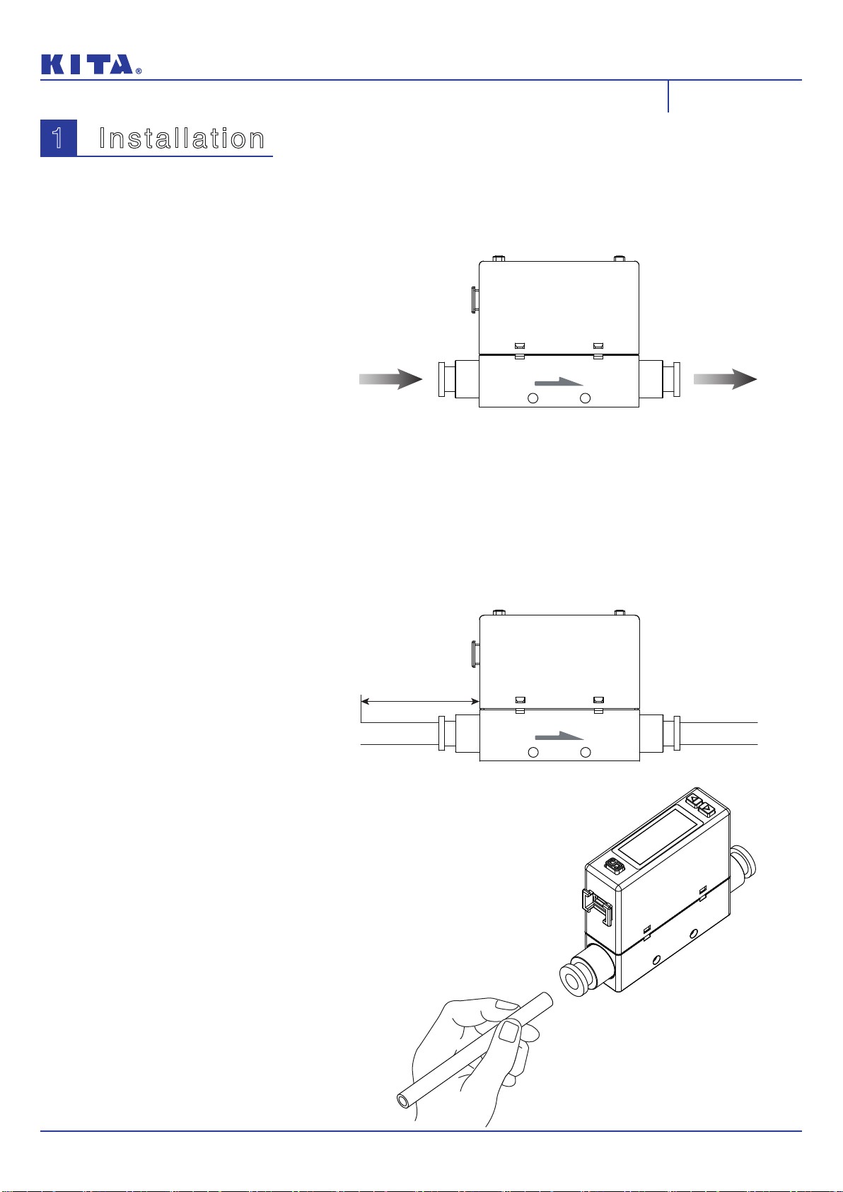
Ensure the flow direction of the fluid.
Please follow the flow direction indicator for installation and
piping.
Flush out all dirt and dust by air blow before connect
the piping to the sensor.
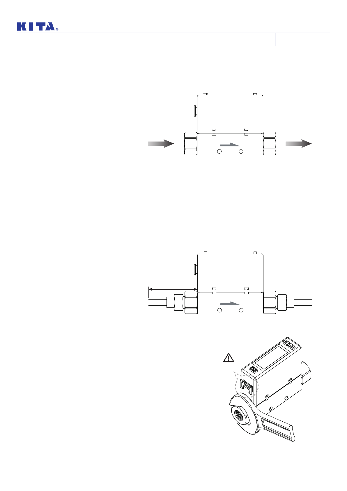
Do not drop or hit.
When installation, do not drop, hit or apply excessive shock
(100m/s2). Internal damage can cause malfunction even if
the housing appears to be undamaged.
Do not install multiple products in close proximity.
The heat generated from each product could cause the
temperature to rise and change the characteristics of
product or deterioration of the plastic parts. Please set the
products 10mm apart from each other.
Hold the sensor body when installing.
The tensile strength of the cable is 24.5 N and apply
excessive pulling force can cause damage to the sensor.
➀
➁
➂
➃
➄
■ Other Precautions
After power is supplied, the output will remain off until
the display is turned on. Please operate the sensor
after the value is shown.
Stop the control systems before perform setting
changes.
During the initial flow and pressure setting, the product will
switch the output according to the existing settings until the
changes are complete.
➀
➁
■ Installation Precautions ■ Maintenance Precautions
The accuracy could change by 2 to 3% when the
piping is removed or replaced.
Do not insert a stick or wire into the piping ports.
Do not touch the terminals or connectors when power
is on.
➀
➁
➂
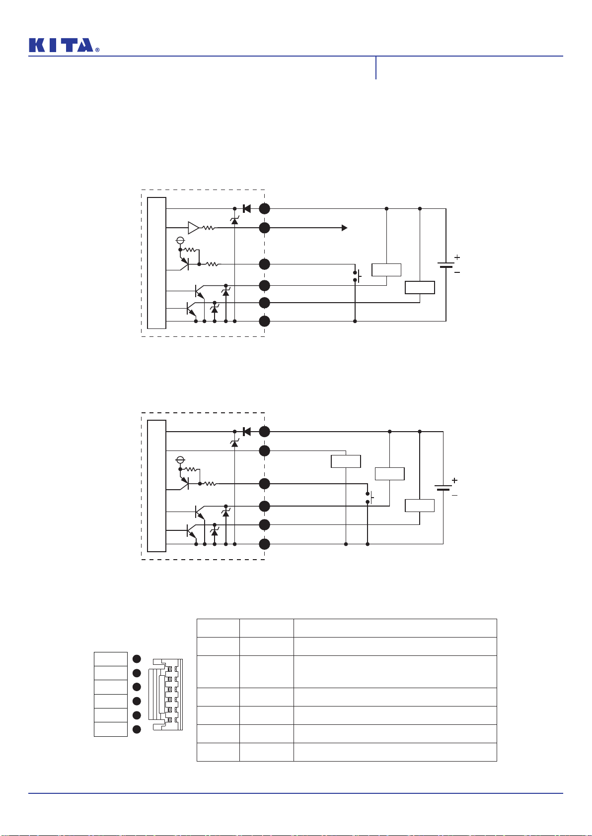
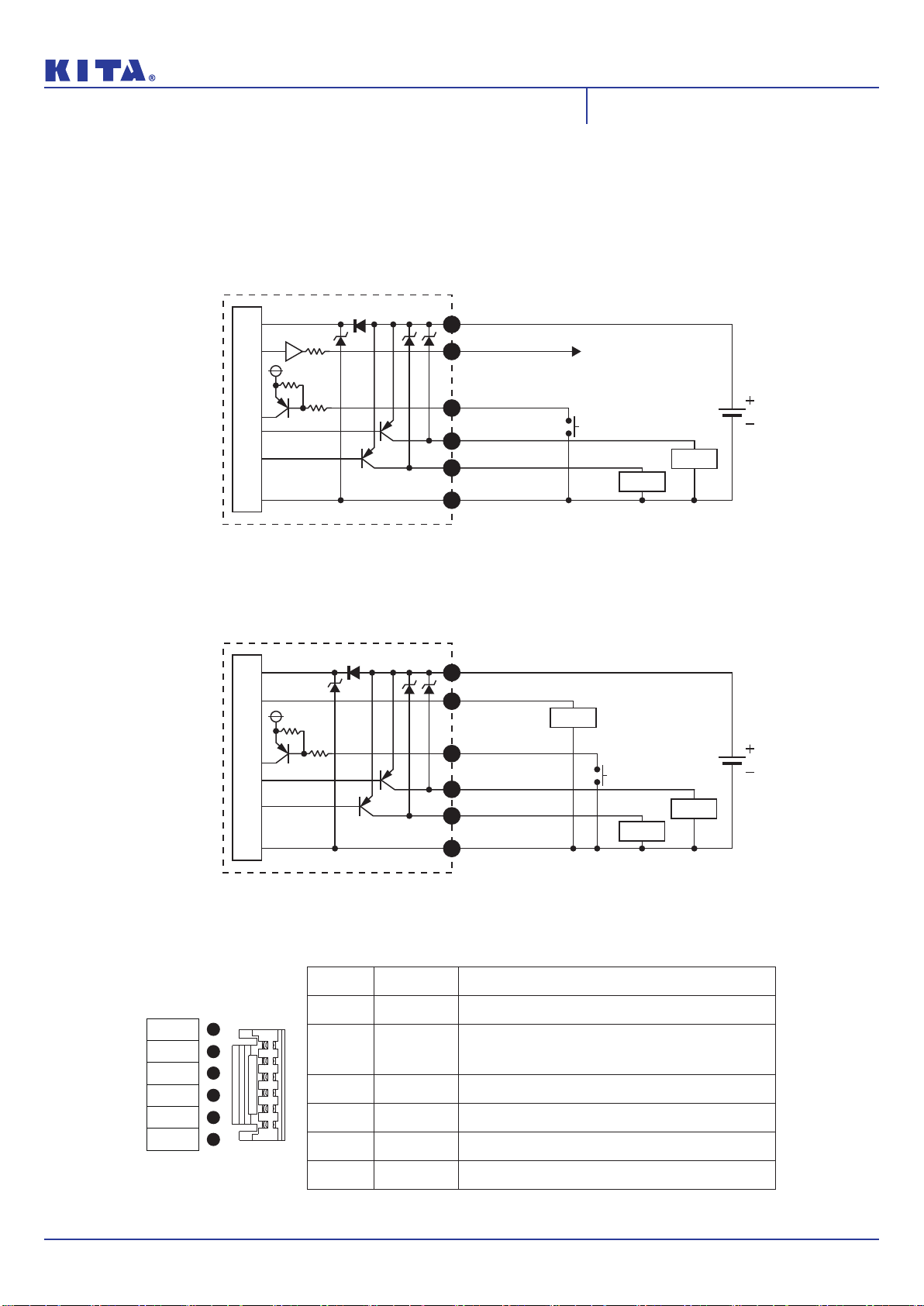
■ Wiring Precautions
Check wire color and terminal number when wiring.
Incorrect wiring can cause permanent damages to the
sensor, check wire color and terminal number against the
manual before wiring.
Avoid repeatedly bending or stretching the lead wire.
It can cause damage to the sheath, or breakage of the
wire.
Confirm wiring insulation
Please avoid poor insulations (and interference from
another circuit, poor insulation between terminals, etc.) it
can lead to over current being applied to the product,
causing damage.
Do not route wires and cables together with power or
high voltage cables.
The product may malfunction due to interference or noise
and surge voltage from power and high voltage cables.
Do not short-circuit the load.
When the load is short-circuited, an error will be displayed.
But excess current may cause damage to the sensor.
Do not connect wire when the power is on.
It may cause damages to the sensors/equipment/machines.
RS485 products must be connected the communica-
tion wire first.
To prevent product damage due to short circuit , MUST do
RS485 line conneciton BEFORE power line connection.
➀
➁
➂
➃
➄
➅
➆
Warning
Caution
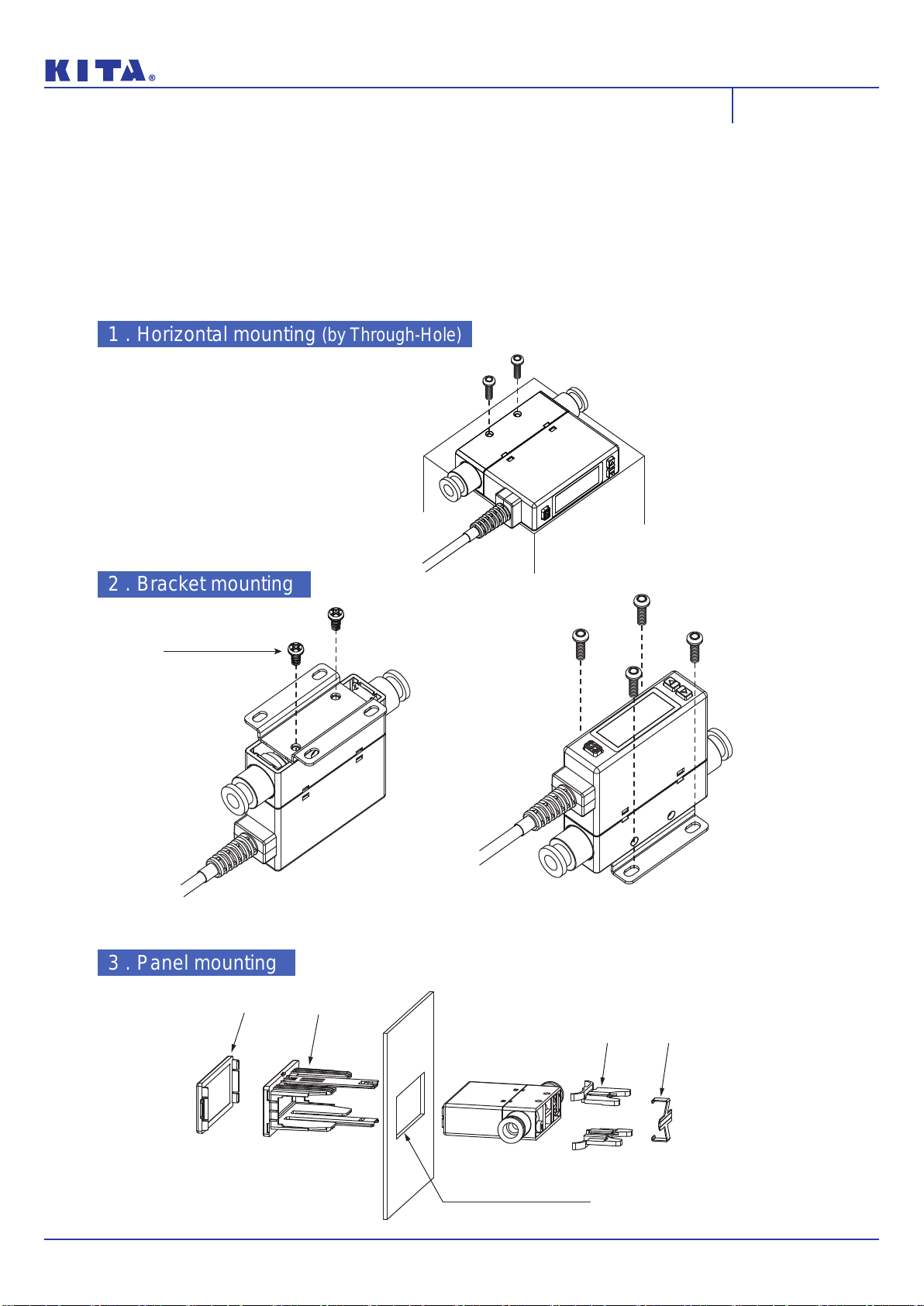
Please follow the specified tightening torque.
Over tighten will damage the product.
Do not mount the sensor in a place that will be used
as a foothold.
The product may damage if sit or step on it accidentally.
When mounting without a bracket, please use P type
self-tapping screw- M3 x L 6mm.
Do not remove the fixed pin for the One-Touch Fitting.
To avoid losing the internal parts and cause malfunction.
Please do not replace fittings by yourself.
While installing the KFP01-101/201 to the pipe, please
apply air tube with I.D. 5 mm.
While installing the KFP01-005/010/050/100/500 to
the pipe, please apply air tube with I.D. 4 mm.
➀
➁
➂
➃
➄
➅
■ Disposal
Sensors at end-of-life must be disposed of in accor-
dance with E-Waste regulations of the country/region,
NOT disposed of with regular garbage.
➀

KFP01 Series Instruction Manual
@2019 KITA Sensor Tech. Co., LTD. URL http://www.kita.com.tw
-3-
■ Fluid
Disclaimer
Check the regulator and flow adjustment valve before
introducing the fluid.
If the pressure or flow rate exceeded the specified range,
the sensing element may be damaged.
Recommended Equipments and Installation
Recommended Equipments and Installation Example
Our warranty applies solely to our product, not to any other damages and injuries which occur by earthquakes,
fires, the acts by third party, other matters, acts intentionally, acts accidentally, misuse, or other abnormal conditions
that are not the responsible of KITA.
Our warranty applies solely to our product, not to any other additional damages (the loses of business profits,
business interruption, etc.) incurred due to using or misusing the product.
Our warranty excludes any injuries and damages happened by using the product beyond the specified range of
catalog or/and not following the instruction manual.
➀The sensing element cannot measure properly if
foreign matter adheres to it.
On the inlet side, be sure to install an air filter below
the filtration level of 10um.
➁
➂
➃
➀
➂
➁
➄
KFP01 Series
Pressure Sensor
Flow Sensor
Or
Flow Sensor
KFP01 Series
Pressure Sensor
Or
Air Source
Filter
Regulator
Micro Mist Separator
(Oil Mist Filiter)
Air Dryer
KFP01 Series
Flow Sensor
Pressure Sensor
※NOTE:
When measuring the pressure of the inlet side, install a throttle valve or solenoid valve on the outlet side.
When measuring the pressure of the outlet side, install a throttle valve or solenoid valve on the inlet side.
Inlet
Outlet
Air Source
Filter
Regulator
Micro Mist Separator
(Oil Mist Filiter)
Air Dryer
Inlet
Outlet
Throttle Valve
※NOTE:When measuring the pressure of the inlet side, install a throttle valve or solenoid valve on the outlet side.
※NOTE:When measuring the pressure of the outlet side, install a throttle valve or solenoid valve on the inlet side.
Air Source
Filter
Regulator
Micro Mist Separator
(Oil Mist Filiter)
Air Dryer
Throttle
Valve
Inlet
Outlet
Warning

@2019 KITA Sensor Tech. Co., LTD. URL http://www.kita.com.tw
-4-
Contents
KFP01 Series Instruction Manual
[ CONTENTS ]
1. Installation Instructions ................................................................................... 5
1.1 Piping .......................................................................................................... 5
1.1.1 Piping for the One-Touch Fitting ............................................... 5
1.1.2 Piping for the internal thread ...................................................... 6
1.2 Mounting bracket ......................................................................................7
1.3 Wiring .......................................................................................................... 8
1.3.1 NPN output, Analog output and external input ....................... 8
1.3.2 PNP output, Analog output and external input ....................... 9
1.3.3 NPN output, RS-485 Modbus .................................................... 10
1.3.4 PNP output, RS-485 Modbus .................................................... 10
2. How to Use ........................................................................................................ 11
2.1 Names and Functions of Individual Parts ........................................... 11
2.2 Functions Instructions ............................................................................. 12
2.3 Operation Setting ..................................................................................... 14
3. Modbus RTU Instruction ................................................................................. 45
4. Error Code Instruction ..................................................................................... 47
5. Specifications..................................................................................................... 48
6. Thermal Mass Principles of Flow Sensor ................................................... 49
7. Ordering Information ....................................................................................... 49
8. Dimensions ........................................................................................................ 50
9. Internal Structure .............................................................................................. 52
This manual suits for next models
2
Table of contents
Other KITA Accessories manuals