MODEL KP1 - □- 01 KP1 - □- 02 KP1 - □- 03
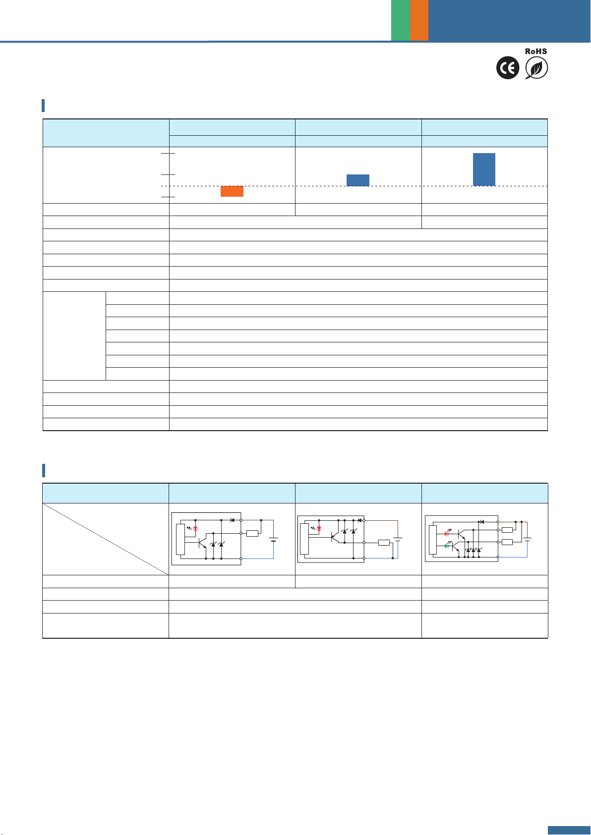
Connect Diagram
Characteristics
Output Method NPN open collector 30 V 80 mA PNP open collector 80 mA NPN open collector 30 V 80 mA
Hysteresis 1 ~ 10 % of setting pressure ( Adjustable ) ≤ 3 % F.S. ( Fixed )
Setting Points 1 Point 2 Points
Operation Indicating Lamp Red LED turns on Out1 = Red,
Out2 = Green
Specications
21
Circuit Wiring Diagrams
DC
12-24V
DC(+)
DC(-)
OUT
30V, 80mA
Red
Black
Blue
RL
Main Circuit
DC
12-24V
DC(+)
DC(-)
OUT
80mA
Red
Brown
Black
Blue
RL
Main Circuit
Main Circuit
DC
12-24V
DC(+)
DC(-)
OUT1
OUT2
30V, 80mA
30V, 80mA
Red
Green
Brown
Black
Blue
White
RL
RL
Pressure Sensor
MODEL KP1-1 KP1-2 KP1-3
Vacuum Low Positive
Set Pressure Range -101 ~ 0 kPa 0 ~ 100 kPa 0 ~ 1 MPa
Withstand Pressure 300 kPa 1.5 MPa
Fluid Filtered air, Non-corrosive / Non-ammable gas
Power Supply Voltage 12 ~ 24 V DC ± 10 %, Ripple ( P-P ) ≤ 10 %
Current Consumption 1 NPN or 1 PNP output : ≤ 21 mA ; 2 NPN output : ≤ 35 mA
Repeatability ± 1 % F.S.
Response Time ≤ 5 ms
Environment
Enclosure IP40
Ambient Temp. Range
Operation : 0 ~ 50 °C, storage : -20 ~ 60 °C ( No condensation or freezing )
Ambient Humidity Range
Operation / Storage : 35 ~ 85 % RH ( No condensation )
Withstand Voltage
1000 V AC in 1-min ( between case and lead wire )
Insulation Resistance
≥ 50 MΩ ( at 500 V DC, between case and lead wire )
Vibration Total amplitude 1.5 mm or 10 G, 10 Hz ~ 55 Hz ~ 10 Hz scan for 1 minute, 2 hours each direction of X, Y and Z
Shock 980 m/s² ( 100 G ), 3 times each in direction of X, Y and Z
Temperature Characteristic ± 3 % F.S. of detected pressure ( 25 °C ) at temp. ( Range of 0 ~ 50 °C )
Port Size PT : 1/8"PT ( R1/8" ), M5 ; NPT : NPT1/8", M5 ; G : G1/8" ( BSPP ), M5
Lead Wire Ø4 Oil-resistance cable ( PVC ) - 24 AWG ( 0.22 mm² ) - 3 cores
Weight ( with 1 meter lead wire ) Approx. 50 g
1 MPa
0
-101 kPa
100 kPa


