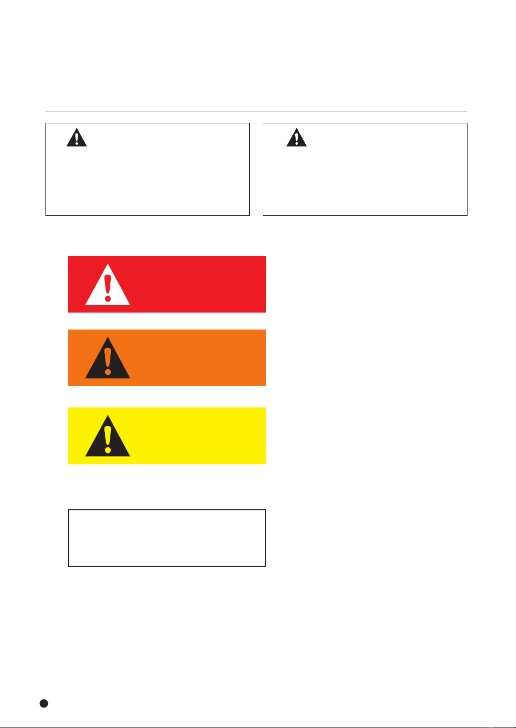
Kitagawa JM200 User manual

type
JM200
治具モジュール
JIG MODULE
将来いつでも使用できるように大切に保管すること。
PleaseReadandKeepThisManualinaSafePlace.
取扱説明書
INSTRUCTIONMANUAL
重要
Important
この取扱説明書は製品の操作を担当する生産技術
者および保守担当者を対象にして記載しています。
初心者がご使用される場合は経験者、お買い上げ
販売店、あるいは㈱北川鉄工所の指導を受けて下
さい。
取扱説明書本文にでてくる警告事項の部分は、製
品を使用する前に注意深く読み、内容を充分ご理
解下さい。
この取扱説明書の警告事項に従わなかった場合に
生ずる不具合、事故についての責任は負いかねます。
Thismanualispreparedforproductionengineers
andmaintenanceservicementooperatethe
products.lfabeginneroperatestheproducts,he
shouldbefirstlytrainedbyeitheraskilledman,
theagentyoupurchasedtheproductsfromor
KitagawaTechnicalDepartmentpriortothe
operation.
Carefullyreadthewarningitemsinthismanual
and understand them thoroughly prior to
the operation. Warranty does not coverany
damage oraccident causedwithout following
thewarningitems.
◇
◇
◇
◇
株式会社
北川鉄工所 キタガワ
グローバル
ハンド
カンパニー
〒726
−
8610
広島県府中市元町
77
−
1
Tel.(0847)40-0561 Fax.(0847)45-8911
Kitagawa
Corporation KitagawaGlobalhandCompany
77
-
1
,Motomachi,Fuchu-shi,Hiroshima,726-8610,Japan Tel.+81-847-40-0561 Fax.+81-847-45-8911
■ 国内
東京営業課
仙台支店駐在
名古屋営業課
大阪営業課
広島営業課
九州支店駐在
海外営業課
埼玉県さいたま市北区吉野町1-405-1
宮城県仙台市若林区大和町4-15-13
愛知県名古屋市中川区上高畑2-62
大阪府大阪市住之江区北加賀屋3-2-9
広島県府中市元町77-1
福岡県福岡市博多区板付7-6-39
広島県府中市元町77-1
〒331-9634
〒984-0042
〒454-0873
〒559-0011
〒726-8610
〒812-0888
〒726-8610
Tel.(
048
)667-3469
Tel.(
022
)232-6732(
代
)
Tel.(
052
)363-0371(
代
)
Tel.(
06
)6685-9065(
代
)
Tel.(
0847
)40-0541
Tel.(
092
)501-2102(
代
)
Tel.(
0847
)40-0526
Fax.(
048
)663-4678
Fax.(
022
)232-6739
Fax.(
052
)362-0690
Fax.(
06
)6684-2025
Fax.(
0847
)46-1721
Fax.(
092
)501-2103
Fax.(
0847
)45-8911
本取扱説明書記載の商品は「外国為替及び外国貿易法」の「輸出貿易管理令」及び「外国為替令」の規制対象貨物です。同法に基づき、経済産業省大臣による
輸出許可が必要となる場合がございます。日本国外へ持ち出される場合は、あらかじめ当社にご相談ください。
TheproductshereinarecontrolledunderJapaneseForeignExchangeandForeignTradeControlAct.Intheeventofimportingand/orexportingtheproducts,
youareobligedtoconsultKITAGAWAaswellasyourgovernmentfortherelatedregulationpriortoanytransaction.
■ 海外
/
OVERSEAS
https://www.kitagawa.com.cn
https://www.kiw.co.jp
https://www.kitagawa.com
KITAGAWA-NORTHTECHINC.
KITAGAWAEUROPELTD.
KITAGAWAEUROPEGmbH
KITAGAWAEUROPEGmbHPolandOffice
KITAGAWAEUROPEGmbHCzechOffice
KITAGAWAEUROPEGmbHRomaniaOffice
KITAGAWAEUROPEGmbHHungaryOffice
KITAGAWAINDIAPVTLTD.
KITAGAWA(THAILAND)CO.,LTD.BangkokBranch
KitagawaCorporation(Shanghai)
KitagawaCorporation(Shanghai)GuangzhouOffice
DEAMARKLIMITED
KITAGAWAKOREAAGENTCO.,LTD.
DIMACTOOLINGPTY.LTD.
Tel.+1 847-310-8787
Tel.+44 1725-514000
Tel.+49 2102-123-78-00
Tel.+48 607-39-8855
Tel.+420 603-856-122
Tel.+40 727-770-329
Tel.+36 30-510-3550
Tel.+91-80-2976-5200
Tel.+66 2-712-7479
Tel.+86 21-6295-5772
Tel.+86 20-2885-5276
Tel.+886 2-2393-1221
Tel.+82 2-2026-2222
Tel.+61 3-9561-6155
Fax.+1 847-310-9484
Fax.+44 1725-514001
Fax.+49 2102-123-78-69
Fax.+91-80-2976-5205
Fax.+66 2-712-7481
Fax.+86 21-6295-5792
Fax.+886 2-2395-1231
Fax.+82 2-2026-2113
Fax.+61 3-9561-6705
AmericaContact
EuropeContact
AsiaContact
OceaniaContact
https://www.kitagawa-usa.com
https://www.kitagawa.global/en
https://www.kitagawa.global/de
https://www.kitagawa.global/pl
https://www.kitagawa.global/cz
https://www.kitagawa.global/ro
https://www.kitagawa.global/hu
https://www.kitagawa.global/in
https://www.kitagawa.com.cn
http://www.deamark.com.tw
http://www.kitagawa.co.kr
https://www.dimac.com.au
D2021.02.0000

1
2
DANGER
危 険
WARNING
警 告
CAUTION
注 意
もし回避されなければ、死亡または重
大な傷害を生じるであろう差し迫った
危険状況を示す。
Indicatesanimminentlyhazardous
situationwhich,ifnotavoided,will
resultindeathorseriousinjury.
もし回避されなければ、死亡または重
大な傷害を生じることがあり得る潜在
的な危険状態を示す。
Indicatesapotentiallyhazardous
situationwhich,ifnotavoided,could
resultindeathorseriousinjury.
もし回避されなければ、軽傷または中
程度の傷害が発生するかもしれない潜
在的な危険状態を示す。
Indicatesapotentiallyhazardous
situationwhich,ifnotavoided,may
resultinminorormoderateinjury.
知っておくと得な製品の性能、
誤りやすいミスに関する事項。
Instructionsfor jigmoduleperformance
andavoidingerrorsormistakes.
「K ITAGAWA」の治具モジュールをご愛用いただき厚く
お礼申し上げます。
この取扱説明書によって治具モジュールの使用方法を正し
くご理解いただき、貴社の生産に寄与できますようご活用
いただければ幸いに存じます。
Keepthismanualhandyfor easy reference as it will
helpyouusemanycontrolstotheirfulladvantage.
IMPORTANT
留意事項
これは業界の「安全アラート・シンボル」です。このシンボルは、
この装置の使用に伴い、あなたや他の人々に危険をおよぼすおそ
れのある事項や操作について、あなたの注意を喚起しています。
これらの指示に注意深く従ってください。この装置の組立または
使用の前に、あなたが指示事項や安全基準を読むことは大切なこ
とです。
安全アラート・シンボル
Thisis theindustrySafetyAlertSymbol.Thissymbolis
usedtocallyourattentiontoitemsoroperationsthatcould
bedangeroustoyouorotherpersonsusingthisequipment.
Pleasereadthesemessagesandfollowtheseinstructions
carefully.
Itisessentialthatyoureadtheinstructionsandsafety
regulationsbeforeyouattempttoassembleorusethisunit.
SAFETYALERTSYMBOL
警告事項
留意事項
目 次
ご使用にあたって、安全のために
1.治具モジュールの構造図及び部品表
2.把握機能及び使用方法と仕様
2-1把握機能及び使用方法
2-2同期と揺動の切り替え方法
2-3仕様
2-4検査項目
3.トップジョーの成形及びロケータの製作
3-1トップジョーの成形
3-2ロケータの取付方法
3-3ロケータとトップジョーの構成
4.取付・配管
4-1取付方法
4-2配管
4-3近接スイッチ
5.使用上の注意
6.保守点検
6-1給油
6-2分解と清掃
7.故障と対策
8.ロックバルブユニット(LV-3)
使用について
8-1取付方法
8-2保守点検
9.ロックバルブユニット(LV-3)
部品表
TABLEOFCONTENTS
Forsafeoperation
1.Drawingandpartslistofjigmodule
2.Mounting
2-1
MountingofCylinderandAirTubeAssy(Option)
2-2
ExchangeofSynchronizationandFluctuation
2-3Specifications
2-4Inspectionitem
3.
Formingoftopjawsandmanufactureoflocator
3-1Formingoftopjaws
3-2Tomountlocator
3-3
Configurationoflocatorandtopjaws
4.MountingandPiping
4-1Mountingmethod
4-2Piping
4-3Proximityswitch
5.Precautionsforuse
6.Maintenanceandinspection
6-1Lubrication
6-2Disassembleandcleaning
7.Troubleandtroubleshooting
8.Useoflockvalveunit(LV-3)
8-1Mountingmethod
8-2Maintenanceandinspection
9.Partslistoflockvalveunit(LV-3)
……… 3
…… 8
……………12
………………12
…………14
……………………………………15
………………………………17
…18
…………………18
…………………20
……21
…………………………………27
………………………………27
……………………………………29
…………………………31
………………………………32
……………………………………33
……………………………………33
……………………………35
…………………………………36
…………………………38
………………………………38
………………………………38
…………………………………40
………………………… 3
……… 8
……………………………………12
…12
…14
…………………………15
…………………………17
…18
……………………18
………………………20
…21
………………………27
………………………27
……………………………………29
………………………31
…………………………32
………………33
………………………………33
……………35
………………37
………………38
………………………38
…………38
…………40

3
4
ご愛用にあたって、安全のために
ForSafeOperation
ご使用の前に特に知っておいていただきたいこと、守っ
ていただきたいことをまとめてあります。必ずお読み下
さい。
尚、この取扱説明書の警告事項に従われなかった場合に
生ずる不具合、事故についての責任は負いかねます。
Please readthismanual and followinstructions
carefully.
We cannot assumeresponsibilityfordamage or
accidents caused by misuse of the jig module,
throughnon-compliancewiththesafetyinstructions.
治具モジュールの取付、点検、給油、交換時には、電源を切ること。
SWITCH
OFF
powerbeforesetting,inspecting,lubricating
andchangingthejigmodule.
工作物加工時は切換弁を操作しないこと。
Neveroperatechangevalveonworkpieceoperation.
DANGER
危 険
WARNING
警 告
電磁弁は無通電時、把握する回路とすること。(P 参照)
Whenpowerisrestoredthesolenoidvalveresumesitsnormal
function.(Seepage )
手動切換弁
Manualoperatedvalve
把握した工作物が飛散し危険。
Grippedworkpiecewilldischarge.
電磁弁
Solenoidcontrolledvalve
判断力の低下や誤操作により危険。
Failingtodosocouldcauseoperationalmistakeandimpairjudgment.
体の一部や衣服が巻き込まれる危険がある。
Fallingtodosocouldcausecatchingthe
operatorinthemachine.
落雷・停電時切削力により工作物が飛散し危険。
Workscattersiflightingorpowerinterruptionoccurs.
把握側へ
Toclampingside
落雷
=
停電
LIGHTNING
INTERRUPTION
ON
OFF
IN EX H
アルコール又は薬物を飲んで操作してはならない。
Neverattempttooperateamachinewhileundertheinfluence
ofalcoholordrugs.
Alcohol
アルコール
Drugs
薬物
機械に巻き込まれ危険。
Failingtodosocouldcausecatchingtheoperatorinthemachine.
手袋、ネクタイ等を着用して操作してはならない。
Glovesandtiesmustnotbewornwhenoperatingamachine.
OFF
OFF
NO!
NO!
NO!
NO!
STOP
STOP

5
6
治具モジュール、ジョー、工作物へ衝撃を加えないこと。
Neverattempttohammerthejigmodule,jawsorgripped
workpieces.
工作物を把握する時、手をはさまないようにすること。
Whengrippingworkpiece,makesureyourhandisoutof
grippingarea.
精度及び機能を失う。
Accuracyandfunctionwillberuined.
ジョーと工作物、ジョーとボデー、又はジョー
とロケータの間に指を入れないこと。
Neverputfingersinbetweenjawand
workpieceorbodyorlocator.
ジョー取付ボルト
Jawmountingbolt
ブロック取付ボルト
Blockmountingbolt
衝撃shock
エアホースを切離して使用する時はロックバルブのテストをすること。
Testthelockvalvewhenusingthejigmodulewiththeairhose
removed.
ボルトは規定トルクで締付けること。(P⑨参照)
Secureclampboltscorrecttorque.(Seepage⑨)
NO!
NO!
NO!
NO!
MAX. 0.6MPa
MAX. 0.6MPa
ロックバルブ付きの場合、ロックバルブの圧力保持
テストを行った後、稼動させる。
Incasethelockvalveisprovided,performthe
lockvalvemaintainingtestbeforeoperating.
LV-3
0.5MPa(5.1kgf/cm2)の時、1時間で圧力損失が
0.05MPa(0.51kgf/cm2)以下であること。
When0.5MPa
(
5.1kgf/
cm2)
,pressurelossistobe
0.05MPa
(0.5
1kgf/
cm2)
orlessat1hour.
ロックバルブ(LV-3)
Lockvalve(LV-3)
CAUTION
注 意
CAUTION
注 意
最大空圧力0.6MPa(P 参照)
Maximumairpressure:0.6MPa(SeePage )
過大な空圧力を加えると寿命が短くなる。
Ifanexcessiveairpressureisappliedtothechuck,
theservicelifeofchuckbecomesshort.
0.2
0.4
0.8
1.0
0
0.6MPa
MPa
ルブリケーターのオイル量は適正に保つこと。
Alwaysfilllubricatorwithoiluptoproperlevel.
指定されたオイルを使用すること。
Userecommendedoil.
オイルがなくなると把握力低下、錆の発生原因になる。
Whentheoilisdepleted,grippingpowerdiminishes,
andrustdevelopsremovewater.
0.1
0.2
0.4
0.6
0.8
1.0
MPa
MAX.
MIN.
OIL

7
8
CAUTION
注 意
安易な改造はしないこと。
Donotattempttomodifyjigmodule.
1.治具モジュールの構造図及び部品表
1.
Drawingandpartslistofjigmodule
壊れる!
Functionreduces!
NO!
NO!
トップジョーの高さは66㎜以内、幅は86㎜以内までにすること。また、工作
物の高さはロケータ取付け面から140㎜以内までにすること。(P 参照)
Theheightoftopjawistobewithin66mmandthewidthwithin86mm.
Theheightofworkistobewithin140mmfromthemountingfaceoflocator.(SeePage )
46(標準)(Standard)
工作物
66(標準+20)(Standard+20)
52(標準)
(Standard)
86(ボデー幅)
(Bodywidth)
140
ロケータ
ロケータ取付け面
Mountingfaceoflocator
locator
品 名 ・ 規 格
NamesandSpecifications
符号
Mark
符号
Mark
個数
Q'ty
個数
Q'ty
品 名 ・ 規 格
NamesandSpecifications
ボデー
Body
リアボデー
Rearbody
マスタジョー
Masterjaw
ダイヤフラム
Diaphragm
ピストン
Piston
シリンダーカバー
Cylindercover
トップジョー
Topjaw
プランジャー
Plunger
イコライズピン
Equalizepin
ロックボルト
Lockbolt
フロントカバー
Frontcover
ワッシャ
Washer
コテイピン
Fixedpin
プレート
Plate
ブロック
Block
ガイドブロック
Guideblock
クランプ器具(付属品)
Clampdevice
六角穴付ボルト M10×25
Hexagonsocketheadcapscrew
1
2
3
4
5
6
7
8
9
10
11
12
13
14
15
16
17
18
19
20
21
22
23
24
25
26
27
28
29
30
31
32
33
34
35
36
4
5
2
10
2
5
2
1
5
13
1
8
4
4
8
2
2
1
1
1
2
1
1
1
2
1
1
1
1
1
4
2
1
2
4set
4
六角穴付ボルト M8×45
Hexagonsocketheadcapscrew
六角穴付ボルト M8×20
Hexagonsocketheadcapscrew
六角穴付ボルト M6×35
Hexagonsocketheadcapscrew
六角穴付ボルト M5×16
Hexagonsocketheadcapscrew
六角穴付ボルト M6×12
Hexagonsocketheadcapscrew
六角穴付ボタンボルト M5×10
Hexagonsocketbuttonheadcapscrew
六角穴付止めねじ M5×12
Hexagonsocketscrew
アナプラグA
PlugA
アナプラグB
PlugB
アナプラグC
PlugC
オリフィスセット S0510
Orificeset
平座金 8
Plainwasher
スーパースプリング 5571
Superspring
スチールボール 7.9
Steelball
グリスニップル M6×4
Greasenipple
丸マグネット
RoundMagnet
ナイロンキャップオス
Nyloncap
サイレンサ
Silencer
Work

7
8
CAUTION
注 意
安易な改造はしないこと。
Donotattempttomodifyjigmodule.
1.治具モジュールの構造図及び部品表
1.
Drawingandpartslistofjigmodule
壊れる!
Functionreduces!
NO!
NO!
トップジョーの高さは66㎜以内、幅は86㎜以内までにすること。また、工作
物の高さはロケータ取付け面から140㎜以内までにすること。(P 参照)
Theheightoftopjawistobewithin66mmandthewidthwithin86mm.
Theheightofworkistobewithin140mmfromthemountingfaceoflocator.(SeePage )
46(標準)(Standard)
工作物
66(標準+20)(Standard+20)
52(標準)
(Standard)
86(ボデー幅)
(Bodywidth)
140
ロケータ
ロケータ取付け面
Mountingfaceoflocator
locator
品 名 ・ 規 格
NamesandSpecifications
符号
Mark
符号
Mark
個数
Q'ty
個数
Q'ty
品 名 ・ 規 格
NamesandSpecifications
ボデー
Body
リアボデー
Rearbody
マスタジョー
Masterjaw
ダイヤフラム
Diaphragm
ピストン
Piston
シリンダーカバー
Cylindercover
トップジョー
Topjaw
プランジャー
Plunger
イコライズピン
Equalizepin
ロックボルト
Lockbolt
フロントカバー
Frontcover
ワッシャ
Washer
コテイピン
Fixedpin
プレート
Plate
ブロック
Block
ガイドブロック
Guideblock
クランプ器具(付属品)
Clampdevice
六角穴付ボルト M10×25
Hexagonsocketheadcapscrew
1
2
3
4
5
6
7
8
9
10
11
12
13
14
15
16
17
18
19
20
21
22
23
24
25
26
27
28
29
30
31
32
33
34
35
36
4
5
2
10
2
5
2
1
5
13
1
8
4
4
8
2
2
1
1
1
2
1
1
1
2
1
1
1
1
1
4
2
1
2
4set
4
六角穴付ボルト M8×45
Hexagonsocketheadcapscrew
六角穴付ボルト M8×20
Hexagonsocketheadcapscrew
六角穴付ボルト M6×35
Hexagonsocketheadcapscrew
六角穴付ボルト M5×16
Hexagonsocketheadcapscrew
六角穴付ボルト M6×12
Hexagonsocketheadcapscrew
六角穴付ボタンボルト M5×10
Hexagonsocketbuttonheadcapscrew
六角穴付止めねじ M5×12
Hexagonsocketscrew
アナプラグA
PlugA
アナプラグB
PlugB
アナプラグC
PlugC
オリフィスセット S0510
Orificeset
平座金 8
Plainwasher
スーパースプリング 5571
Superspring
スチールボール 7.9
Steelball
グリスニップル M6×4
Greasenipple
丸マグネット
RoundMagnet
ナイロンキャップオス
Nyloncap
サイレンサ
Silencer
Work

9
10
消耗部品 Expendables
品 名 Names 個数
Q'ty
種類
type
Oリング
Oリング
Oリング
Oリング
Oリング
Oリング
Oリング
36
37
38
39
40
41
42
1
2
1
1
4
2
1
O-ring
O-ring
O-ring
O-ring
O-ring
O-ring
O-ring
JASO3140
P50
P24
P16
P7
S150
S56
締付けトルク表 ListofTighteningtorque
NO. ボルトサイズ
Boltsize
タップ穴(材質)
taps(material)
取付けトルクN・m
TighteningTorque
M10
M8
M5
M6
M5
18
19・20
24
21・23
22
鉄(steel)
鉄(steel)
鉄(steel)
アルミニウム(aluminum)
アルミニウム(aluminum)
72.6N・m
33.3N・m
12.7N・m
10.8N・m
5.5N・m
治具モジュール部品リスト Partslistofjigmodule
NO.
18 4327 11
7
3
31
32
38
28
41
26
21
14
15
35
27
41
20
28
29
27
5
37 12 6222040423419 30
23
16
2
17
30
39
94
13
36
8
42
1
28
33
10
25
24

11
12
ワーク着座検知用エア出口
Airoutletforworkseatingdetection
12-M8深さ16
280 0.5
260
216
130
7041 4120 20
10H8
10H8
22 42
40
86
52
14h7
70
50 20
10
120
100
12h7
12-M8depth16
M5深さ11
M5depth11
近接スイッチ関係の寸法
Dimentionsofproximity
switchrelation
M5深さ12
M5depth12
Upperface
onrearbody
Bodyside
リアボデー上面
ボデー側面
Rearbodyside
リアボデー側面
40±0.1 40±0.1
Rc1/4エア供給口(クランプ)
Airinlet(Clump)Rc1/4
Rc1/4エア供給口(アンクランプ)
Airinlet(Unclump)Rc1/4
Rc1/8エア供給口(ワーク着座検知)
Airinlet(forworkseatingdetection)Rc1/8
50
45 30
120
MAX190
4.5 3
MAX7.4
MAX103.4
MIN93
12H7
13
110
20 2
34 34
13
5
40
34
70
ガイドブロック(2ヶ所)
Guideblock(2pcs.)
MAX24
MIN6
40
4.5
46
30°
φ78H7
近接スイッチ関係の寸法
Dimentionsrelatedtoproximityswitch
Rc1/8裏面エア供給口(ワーク着座検知)
BackfaceAirinlet(forworkseatingdetection)Rc1/8
Rc1/8裏面エア供給口(アンクランプ)
BackfaceAirinlet(Unclump)Rc1/8
32
1212
20
2-M6深さ10
2-M6depth10
4-M10深さ23
4-M10depth23
Rc1/8裏面エア供給口(クランプ)
BackfaceAirinlet(Clump)Rc1/8
Fig.1-1
外形図 OutlineView
2.把握機能及び使用方法と仕様
2.Mounting
2
−
1
把握機能及び使用方法
2
−
1
MountingofCylinderandAir
TubeASSY(Option)
治具モジュールは、上物(トップジョー、ロケータ)を取
り替えるだけで異形物から角物まで多種多様な形状の工
作物に対応できるダイカストワーク保持具です。工作物
にあった上物が必要となりますので工作物の形状、寸法
、切削条件などを考慮した最適なロケータ、トップジョ
ーをお客様で用意して下さい。
把握機能は、センタリング把握、コンペ把握、フェイス
クランプの3種類があり特徴は表1の通りです。
Thejigmoduleisthedie-castingworkholdingassembly
corresponding to the various kinds of works from
deformedworkstosquareworksonlybyexchangingthe
top jaws and the locator. Since the top jaws and the
locator suited to works are required, customer shall
prepareoptimumlocatorsandtopjawsinconsideration
ofworkform,dimensions,cuttingconditions,etc.
A clamp function has three kinds of centering clamp,
competitionclampandfaceclamp,andthefeaturesare
asshowninTable1.
X
Z
Y
トップジョー
インロー φ78H7 深さ4.5
(ロケータ位置決め用)
M8タップ ねじ深さ16
(ロケータ取付け用) マスタジョー
空圧供給口(閉)
空圧供給口(開)
ロックボルト(同期・揺動切替用)
カバー
エア出口(ワーク着座検知用)
空圧供給口(ワーク着座検知用)
フェイスクランプ
センタリング・コンペ把握
工作物
ロケータ ロケータ
工作物
Fig.2-2
治具モジュール把握方法 ClampingMethodofJigModule
Fig.2-1
治具モジュール外観図 AppearanceofJigModule
M8tap,threaddepth16
(formountinglocator)
Faucet78H7depth4.5
(forpositioninglocator)
Masterjaw
Cover Lockbolt(forsynchronism/fluctuationchange)
Topjaw
Airoutletforworkseatingdetection
Airinlet(forworkseatingdetection)
Airinlet(CLOSE)
Airinlet(OPEN)
Work Work
Locator
Locator
Centralizing/compensatingclamp Faceclamp

13
14
治具モジュールはエアシリンダを内蔵しており、空圧供
給口(閉)に空圧を供給すると、トップジョーが斜め下に
動いてクランプ動作をし、空圧供給口(開)に空圧を供給
すると斜め上に動いてアンクランプ動作を行います。
3種類いずれの把握でも工作物をZ軸方向に引込む機能
があります。
センタリング把握は2つのトップジョーが同期して動く
ことで、工作物のX軸方向の位置決めを行います。コン
ペ把握、フェイスクランプは、2つのトップジョーが揺
動することで、ロケータで位置決めされた工作物になら
って把握します。これにより、工作物の寸法にバラツキ
があっても安定した把握が可能になります。
The jig module incorporates the cylinder. When air is
suppliedtothe airinlet(CLOSE),thetopjawsmove in
obliquely downward toclamp the work. When air is
suppliedtotheairoutlet(OPEN),thetopjawsmovein
obliquelyupwardtounclampthework.
The chuck functions to draw the work in the Z-axis
direction even if any method among three clamping
methodsisused.
Inthecentralizingclamp,twotopjawspositionthework
bymovinginX-axisdirection,synchronizingthem.Inthe
compensating clamp and the face clamp, two top jaws
fluctuateand clamp the work positionedbythelocator.
Asaresult,thechuckcanclamptheworkstablyevenif
thedimensionsofworkvarywidely.
表1.把握機能と特徴
ジョー動作把握機能(3種類) 工作物の位置決め 把握方法
2つのトップジョー
が同期して動く
2つのトップジョー
が揺動して動く
2つのトップジョー
が揺動して動く
センタリング把握
コンペ把握
フェイスクランプ
X軸方向 2つのトップジョーによる位置決め
Y軸方向 ロケータによる位置決め
Z軸方向 ロケータ基準面による位置決め
X軸方向 ロケータによる位置決め
Y軸方向 ロケータによる位置決め
Z軸方向 ロケータ基準面による位置決め
X軸方向 ロケータによる位置決め
Y軸方向 ロケータによる位置決め
Z軸方向 ロケータ基準面による位置決め
工作物外面を2つの
トップジョー側面で
挟むことにより把握
工作物外面を2つの
トップジョー側面で
挟むことにより把握
工作物上面をトップ
ジョー下面にて押さえ
込むことにより把握
Table1.ClampFunctionsandFeatures
Jawmotion
Clampfunction
(3kinds) Positioningofwork Clampingmethod
Twotopjawsmove,
synchronizing.
Twotopjawsmove,
fluctuating.
Twotopjawsmove,
fluctuating.
Centralizingclamp
Compensatingclamp
Faceclamp
X-axisdirection:Positionedbytwotopjaws.
Y-axisdirection:Positionedbylocator.
Z-axisdirection:
Positionedbylocatordatumlevel.
X-axisdirection:Positionedbylocator.
Y-axisdirection:Positionedbylocator.
Z-axisdirection:
Positionedbylocatordatumlevel.
X-axisdirection:Positionedbylocator.
Y-axisdirection:Positionedbylocator.
Z-axisdirection:
Positionedbylocatordatumlevel.
Outerfacesofwork
areclampedbytwo
topjawsidefaces.
Outerfacesofwork
areclampedbytwo
topjawsidefaces.
Upperfaceispushed
bybottomfacesof
topjaws.
2
−
2
同期と揺動の切替え方法
トップジョーの同期と揺動の切換えはFig.2-3のように
ロックボルトにて行います。
(1)揺動から同期への切換え
止めねじ(2本)を3回転以上緩めた後、ロックボル
トを時計回りにトルクレンチ38.2N・mで締め付け、
緩まないように止めねじ(2本)にて回り止めをし
ます。
(2)同期から揺動への切換え
止めねじ(2本)を緩めた後、ロックボルトを反時
計回りに、止まるまで軽く回転させ、止めねじ
(2本)にて回り止めをします。
The synchronization and fluctuation of top jawsare
changedbylockboltasshowninFig.2-3.
(1)Changedtosynchronizationfromfluctuation
Afterlooseningtwosetscrews3-rotationormore,
tightenthelockboltclockwiseattorque38.2N・m
withthetorquewrenchandlockthelock boltwith
twosetscrewssoasnottobeloosened.
(2)Changedtofluctuationfromsynchronization
After loosening two lock bolts, rotate the lockbolt
counterclockwise slightly until they stop andlock
the lock bolt with two set screws until they stop.
2
−
2
ExchangeofSynchronization
andFluctuation
CAUTION
注 意
止めねじを緩めずにロックボルトの切換えを行うと部
品が破損することがあります。また、同期から揺動へ
の切換えの際、強いトルクで反時計回りに締めると部
品が破損することがあります。
If the lock bolt is rotated without loosening set
screws, parts may be broken. Moreover, when
changing to fluctuation from synchronization, do
not tighten the lock bolt atastrong torque
counterclockwisebecausepartsmaybebroken.
揺動状態
同期状態
ロックボルト反時計回り(揺動)
ロックボルト時計回り(同期)
止めねじ(六角穴付止めねじM5×12)
(ロックボルトが動かないように回り止め機能)
ロックボルト(同期、揺動切替え)
Fig.2-3
トップジョーの同期と揺動の切換方法
Exchangeofsynchronizationandfluctuationoftopjaw
Setscrew(HexagonsocketscrewsM5x12)(Lockedsoasnottomovelockbolt.)
Lockbolt(Exchangedtosynchronizationorfluctuationandviceversa.
Clockwiselockbolt(Synchronization)
SynchronousState FluctuationState
Counterclockwiselockbolt(Fluctuation)

15
16
2
−
3
仕様 2
−
3
Specifications
仕様
Specification
シリンダストローク
Cylinderstroke
ジョーストローク(センタリング・コンペ/フェイスクランプ)
jawstroke(centralizing・compensating/facecramp)
最大把握力(センタリング・コンペ/フェイスクランプ)
(centralizing・compensating/facecramp)
最低把握力(センタリング・コンペ/フェイスクランプ)
(centralizing・compensating/facecramp)
最大揺動量(コンペ/フェイスクランプ)
(centralizing・compensating/facecramp)
最高/最低使用空圧力
Max./Min.
把握範囲(センタリング・コンペ/フェイスクランプ)
Grippingdia.
質量(標準トップジョーを含む)
Mass(withstandardtopjaws)
JM200
18
20.8/18
9(918)/5.5(561)
3(306)/1.8(184)
1.5/2.5
0.6/0.2
200/150
19
型式
Model
mm
mm
kN(kgf)
kN(kgf)
mm
Mpa
mm
kg
表2.治具モジュール仕様表 list2.Listofjigmodulespecification
(1)把握力は、給油状態・使用グリース・把握高さ・把
握面状態(摩擦係数)等により異なります。
(2)仕様に記載の最大把握力とは、次の状態における値
です。
①最大把握力は、2つのトップジョーの推力の合計
です。
②ジョーはKITAGAWAの標準トップジョーを使用し、
マスタジョーストロークの1/2の位置で把握力計
端面をロケータに当て、トップジョーの高さの1
/2の位置にし、2つのトップジョーを同期させた
状態で北川把握力計にて測定した数値です。
また、フェイスクランプの場合は、トップジョー
下面で把握力を測定できる専用治具を使用し、マ
スタジョーストローク1/2の位置にし、2つのト
ップジョーを同期させた状態で北川把握力計にて
測定した数値です。
③給油は、北川チャックグリースを使用します。
④ジョー取付ボルトの締付トルクは、規定トルクで
締付ます。
⑤この表の最大把握力は供給圧力が0.6MPaの時です。
(3)空圧力は0.2〜0.6MPaの範囲で使用して下さい。
(4)最大揺動量はFig.2-4に表した通りです。
(1)The gripping force varies byoil supply condition,
grease, gripping height, gripping face state (friction
factor),etc.
(2)The maximum gripping force described in
specificationsmeansthefollowingvalues.
①Themaximumgrippingforceisatotalthrustforce
oftwotopjaws.
②The standard top jaws used are Kitagawaユs
brand. The max. gripping force is the value
measuredwiththeKitagawaユs gripping force
measuring instrument when two top jaws are
synchronized with the end face of gripping force
measuringinstrumenttouchedtothelocatorat1/2
positionof masterjawstrokeand also,the
instrumentarrangedto1/2oftopjawheight.Inthe
face clamp, the max. gripping force is the value
measuredwiththeKitagawaユs gripping force
measuring instrument when two top jaws are
synchronizedat1/2positionofmasterjawstroke
byusing the exclusive jigmeasuringthegripping
forceatthebottomfaceofeachtopjaw.
③LubricateKitagawaユschuckgreaseforlubrication.
④Jaw mounting bolts are tightened at a specified
torque.
⑤The maximum gripping force in this list is when
supplypressureis0.6MPa.
(3)Usetheairpressureatrangeof0.2−0.6MPa.
(4)MaximumfluctuationvalueisshowninFig.2-4.
以下
mmorless
Fig.2-4
揺動状態図(単位は㎜)FluctuationStateDrawing(Unit:mm)
○同期状態では2つのマスタジョーの高さがそろった状態⊿Z=0 ⊿X=0で動作します。
○揺動状態では2つのマスタジョーのZ軸方向高さが−1.25≦⊿Z≦+1.25の範囲X軸方向高さが
−0.75≦⊿X≦+0.75の範囲で自由に動作します。
○Z軸方向の最大揺動量は、(最大△Z)−(最小△Z)=2.5㎜となります。
○X軸方向の最大揺動量は、(最大△X)−(最小△X)=1.5㎜となります。
○Insynchronizationstate,thechuckoperateswithheightsoftwomasterjawsuniformed⊿Z=0,⊿X=0.
○ In fluctuation state, the chuck operates freely when two master jaws are within -1.25≦⊿≦+1.25 in Z-axis
directionand-0.75≦⊿≦+0.75inX-axisdirection.
○Max.fluctuationamountinZ-axisdirectionis(Max.△Z)−(Min.△Z)=2.5mm.
○Max.fluctuationamountinX-axisdirectionis(Max.△X)−(Min.△X)=1.5mm.
⊿Z
Z
同期状態→⊿Z=0
揺動状態→−1.25≦⊿Z≦+1.25
⊿X
⊿X
揺動状態→−0.75≦⊿X≦+0.75
同期状態→⊿X=0
⊿Z=0の基準位置
⊿X=0の基準位置
Synchronizationstate→⊿Z=0
Fluctuationstate→−1.25≦⊿Z≦+1.25
Fluctuationstate→−0.75≦⊿X≦+0.75
Referencepositionof⊿X=0
Referencepositionof⊿Z=0
Synchronizationstate→⊿X=0

17
18
検査項目
Inspectionitem
ボデー上面からリアボデー下面の高さ
Heightfromupperfaceofbodytolowerfaceofrearbody
ボデー上面からリアボデー下面の平行度
Parallelismofupperfaceofbodyandlowerfaceofrearbody
リアボデー下面のキー溝とボデー上面のキー溝、φ78インロー部分の対称度
Symmetryforkeywayoflowerfaceofrearbody,keywayofupperfaceofbodyandφ78centeringlocation
位置再現精度(ジョーストローク方向に対して)
Reproducibilityofposition(forjawstrokedirection)
型式
Allowablevalue
120±0.03
0.02
0.1
0.015
表3.検査項目表 Table3.Inspectionitem
Fig.2-5
検査詳細図 DetailedInspectionDrawing
2
−
4
検査項目
ボデー上面のキー溝
Keywayofupperfaceofbody
ボデー下面のキー溝
Keywayoflowerfaceofrearbody
インロー部分
Centeringlocation
ボデー上面
Upperfaceofbody
ボデー下面
Lowerfaceofrearbody
2
−
4
Inspectionitem
3.
トップジョーの成形
及びロケータの製作
3
−
1
トップジョーの成形
標準トップジョーを工作物の把握方法やストロークを考
慮して成形して下さい。
下記の図は標準トップジョーの寸法を表わしたものです。
お客様でトップジョーを製作される場合は、Fig.3-1を参
考に取付部の寸法を決めて下さい。
また、トップジョーの高さ寸法は66㎜以下、幅は86㎜
以下にして下さい。
3.
FormingofTopJawsand
ManufacturingofLocator
3
−
1
Formingoftopjaws
Formthestandardtopjawsinconsiderationofgripping
methodsorstrokesofworks.
Thefollowingdrawingshowsthedimensionsofstandard
top jaw. When any customer will manufacture the top
jaws, determine the dimensions of mounting part
accordingtoFig.3-1.Also,theheightofeachtopjawis
tobe66mmorlessandthewidthistobe86mmorless.
Fig.3-1
標準トップジョー寸法 DimensionsofStandardTopJaw
WARNING
警 告
○Z軸方向の全ストローク18 ㎜の内ストロークエンド
3 ㎜では使用しないで下さい。使用するとピストン
がストロークエンドに当たって、把握力が正常にで
なくなり工作物が飛散する可能性があります。
(特にコンペ把握・フェイスクランプの様な揺動状態
の際には注意して下さい。)
○Keep a margin of 3mm from stroke end on a whole
stroke 18mm in Z-axis direction. If the full stroke is
used, the piston touches thestroke end and the
grippingforceisreduced.Asaresult,theworkmaybe
scattered.(Especially,take care whenthe
compensationclampandfaceclampareperformedby
thefluctuationmethod.)
材質:S45C
34
φ17
φ11
110
40
52
34
34.511.5
6
3.53.5
13±0.113±0.1
12h7-0.018
0
12H70
+0.018
Material:S45C

19
20
Fig.3-2
トップジョー成形 FormingofTopJawBody
トップジョー成形は、治具モジュールに取り付けた状態
でも行えます。
(1)トップジョー成形方法
①成形用プラグを用意します。Fig.3-2のように、
トップジョー接触面とボデー接触面はRa1.6仕
上げ程度とし、把握端面は平行度0.02以下、垂
直度0.02以下として下さい。使用するストロー
ク位置に応じて成形用プラグの大きさを決めて
ください。
②治具モジュールをマシニングセンタ等の加工機にクラ
ンプ器具等で固定します 。
③ロックボルトを時計回り(同期した状態)に締めた状態
にして下さい。
注意)揺動して使う場合も同期した状態にする。
④空圧力を工作物加工時と同圧にセットして下さい。
⑤切換弁を操作して、成形用プラグを把握します。
注意)数回把握を繰 返し成形用プラグを安定させる。
⑥成形用プラグを把握したままの状態で工作物把握部
を成形します 。
⑦成形が終わったら、ロケータ等必要な部品を取り付け
て工作物を把握し、ジョーのストロークを確認して下さい。
⑧試し切削を行い、加工精度やスリップ が無いかなどを
確認して下さい。
Thetopjawscanbeformedwiththemmountedtothejig
module.
(1)Formingoftopjaw
①Preparetheplugforforming.Thetopjawcontact
face and the body contact face are finished at
Ra1.6asshowninFig.3-2,andthegrippingend
faceis tobe parallelism0.02or lessand
perpendicularity 0.02 or less. Determine the
formingplugsizeaccordingtothestrokeposition
tobeused.
②Fixthejigmoduletothefinishingmachinesuch
as machining center, etc., with a clamp device,
etc.
③Tightenthelockboltclockwise(synchronized).
Note)To be synchronized when also used for
fluctuation.
④Set the air pressure to the same pressure as
whentheworkismachined.
⑤Clamp the forming plug by operating the check
valve.
Note)Repeatclampingseveraltimestostabilize
theformingplug.
⑥Form the work clamping part with the forming
plugclamped.
⑦Afterforming, mount the required partsof
locator,etc., clamp thework and check the
strokeofeachjaw.
⑧Performthetrialcuttingtocheckthatmachining
accuracyisadequateorthereisnoslip.
0.02
0.02
MAX103.4
MIN93
MAX24
MIN6
X
Z
X
Y
成形用プラグ
トップジョー
成形用プラグ
ボデー
34
6
Formingplug
Formingplug
Topjaw
Body
Fig.3-3
ロケータ取付け用のインロー・タップ穴・キー溝の寸法
Faucet,taphole,keywayformountinglocator
Fig.3-4
着座検知とロケータ取付け Seatingdetectionandlocatormounting
3
−
2
ロケータの取付方法
工作物に適合したロケータを必ず用意して下さい。
ロケータは、インロー、タップ穴、又はキー溝を利用し
て位置決めや取り付けを行って下さい。
寸法と位置はFig.3-3の通りです。
3
−
2
Tomountlocator
Be sure topreparethelocator suitedforthework.
Positionandmount thelocatorbyusingthefaucet,tap
holeorkeyway.Dimensionsandpositionareasshown
inFig.3-3.
(1)着座検知
着座回路を設けることにより、工作物が工作物基
準面に正確に固定させていることを確認すること
ができます。
Fig.3-4のようにロケータに空圧を通す着座配管を
作って下さい。
(1)Seatingdetection
Itcanbecheckedthattheworkiscorrectlyfixedon
thereferencefacebyprovidingaseatingcircuit.
Route the seating pipe that passes through air to
thelocatorasshowninFig.3-4.
12−M8ねじ深さ16
インロー
インロー深さ
30
34 20 41 70 41 20 34
10
(4)
5
5
48
4.5
70
86
10H80
+0.022
10H80
+0.022
φ78H70
+0.03
空圧供給
基準ピン
ロケータに着座配管を作る
ロケータ
工作物
トップジョー
トップジョー
OリングS12.5
工作物基準面
12-M8screwdepth16
Faucetdepth
Topjaw
Topjaw
Referencepin
Locator
Airsupply
O-ringS12.5
Provideseatingpipetolocator.
Work
Workreferenceface
Faucet
Table of contents
Popular Control Unit manuals by other brands

Fujitsu
Fujitsu UMTS Mounting instructions

Corken
Corken B166 Installation, operation & maintenance manual

hengel
hengel Bi-Tronic Control User instructions

Graco
Graco DynaMite 224906 Instructions-parts list

FlexRadio Systems
FlexRadio Systems FLEX-6300 installation guide

Neoway
Neoway N51 Hardware user's guide