manuals.online logo
Brands
  1. Home
  2. •
  3. Brands
  4. •
  5. KitchenAid
  6. •
  7. Other
  8. •
  9. KitchenAid KFGR270 Manual

KitchenAid KFGR270 Manual

This manual suits for next models

4

Other KitchenAid Other manuals

KitchenAid KERC507 User manual

KitchenAid

KitchenAid KERC507 User manual

KitchenAid ARCHITECT KGSS907 User manual

KitchenAid

KitchenAid ARCHITECT KGSS907 User manual

Popular Other manuals by other brands

Opticon EduMic Compatibility guide

Opticon

Opticon EduMic Compatibility guide

Kessil A360W owner's manual

Kessil

Kessil A360W owner's manual

TEFAL ULTRA COMPACT MIXER manual

TEFAL

TEFAL ULTRA COMPACT MIXER manual

Martin Audio WS18X - SCHEMATICS manual

Martin Audio

Martin Audio WS18X - SCHEMATICS manual

Hendrickson AR2 series Service instructions

Hendrickson

Hendrickson AR2 series Service instructions

GO Industries 38017 installation instructions

GO Industries

GO Industries 38017 installation instructions

Cissell 30LBCMAN2 manual

Cissell

Cissell 30LBCMAN2 manual

RIDGID K-60SP manual

RIDGID

RIDGID K-60SP manual

Gage Bilt GB751SH-5 Original instructions

Gage Bilt

Gage Bilt GB751SH-5 Original instructions

OVE SIERRA 60 installation manual

OVE

OVE SIERRA 60 installation manual

ReelCraft 7800 OLB21 operating instructions

ReelCraft

ReelCraft 7800 OLB21 operating instructions

Body Armor 4x4 ECO-SERIES user manual

Body Armor 4x4

Body Armor 4x4 ECO-SERIES user manual

ROBLIN DROP Dimensions

ROBLIN

ROBLIN DROP Dimensions

EMG EMG-ACB BARREL Installation information

EMG

EMG EMG-ACB BARREL Installation information

MiniSolar MT-150 Assembling Guide

MiniSolar

MiniSolar MT-150 Assembling Guide

Parkside PSZ 250 B2 Operation and safety notes

Parkside

Parkside PSZ 250 B2 Operation and safety notes

ABB REM 610 Technical reference manual

ABB

ABB REM 610 Technical reference manual

Tyent ACE-13 user manual

Tyent

Tyent ACE-13 user manual

manuals.online logo
manuals.online logoBrands
  • About & Mission
  • Contact us
  • Privacy Policy
  • Terms and Conditions

Copyright 2025 Manuals.Online. All Rights Reserved.

Part No. 8285350
Installation Instructions and
Use and Care Guide
IMPORTANT:
Installer: Leave Installation Instructions with the consumer.
Consumer: Keep Installation Instructions for future reference.
Save Installation Instructions for local electrical inspector’s use.
Write the model and serial numbers in space provided below before
installing or using outdoor grill.The numbers are stamped on the
identification label located on the underside of grill drip tray. It is also
located on the model/serial number plate, located on heat shield
behind control panel close to the smoker box.
Model # __________________________
Serial #___________________________
IMPORTANT:
Read and save these instructions.
For the way it’s made
®
®
27" (68.6 cm) and 36" (91.4 cm)
Outdoor Grills
(Portable and Built-in — non-combustible construction)
Quick Reference
Table of Contents:
Pages
Before you start
Product dimensions
Built-In installation dimensions
Gas supply requirements
Rotisserie electrical requirements
Installation steps – Portable models
Installation steps – Built-In models
Checking/adjusting burners
Use and Care Information
Grilling tips & chart
Rotisserie tips & chart
Cleaning
Warranty
Requesting Assistance or Service
2
4
4
5
6
7
8-9
9
10 - 12
12 - 14
15
16 - 17
18
19 - 20
27" (68.6 cm)
Portable without
rotisserie shown
Models
KFGR270
KFGR274
KFGR364
Models
KFGN274
KFGN364
27" (68.6 cm)
Built-In with
rotisserie shown
1. Do not install portable or built-in grills
in or on a recreational vehicle,
portable trailer, boat or in any other
moving installation.
2. Always maintain minimum clearances
from combustible construction, see
“Location requirements” section.
3.The outdoor cooking gas appliance
shall not be located under overhead
combustible construction.
4.This outdoor cooking gas appliance
shall be used only outdoors and shall
not be used in a building, garage, or
any other enclosed area.
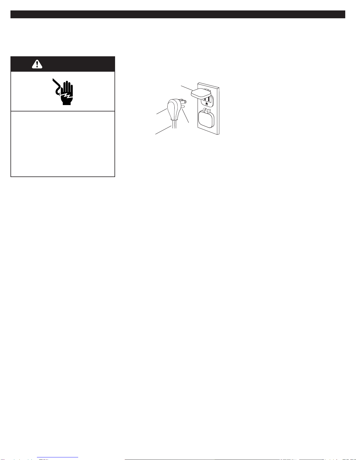
5. Keep any electrical supply cord and
fuel supply hose away from any
heated surfaces.
6. Keep outdoor cooking and appliance
area clear and free from combustible
materials, gasoline and other
flammable vapors and liquids.
7. Do not obstruct the flow of combustion
and ventilation air. Keep the ventilation
openings of the cylinder enclosure free
and clear from debris.
8. Inspect the gas cylinder supply hose
before each use of the grill. If the
hose shows excessive abrasion or
wear, or is cut, it MUST be replaced
before using the grill. Contact your
dealer and use only replacement
hoses specified for use with the grill.
9.Visually check the burner flames.
They should be blue. Slight yellow
tipping is normal for L.P. gas.
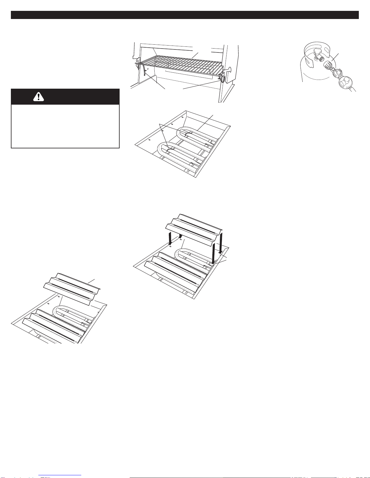
10. Check and clean burner/venturi tube
for insects and insect nest. A clogged
tube can lead to fire under the grill.
11.The L.P. gas supply cylinder to be
used must be:
•constructed and marked in
accordance with the Specification
for L.P. Gas Cylinders of the U.S.
Department of Transportation (DOT)
or the National Standard of Canada,
CAN/CSA-B339, Cylinders, Spheres,
and Tubes for Transportation of
Dangerous Goods; and Commission.
• provided with a listed overfilling
prevention device.
• provided with a cylinder connection
device compatible with the con-
nection for outdoor grill appliances.
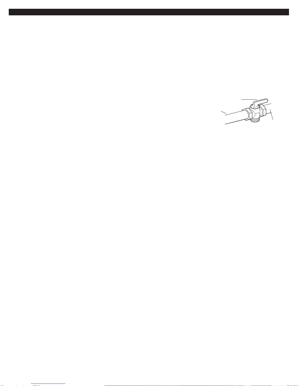
12. Always check connections for leaks
each time you connect and
disconnect the L.P. gas supply
cylinder. See “Installation
Instructions” section.
13.When the outdoor cooking gas
appliance is not in use, the gas must
be turned off at the supply cylinder.
14. Storage of an outdoor gas grill
appliance indoors is permissible only
if the cylinder is disconnected and
removed from the outdoor gas grill.
15. Cylinders must be stored outdoors
and out of the reach of children and
must not be stored in a building,
garage, or any other enclosed area.
16.The pressure regulator and hose
assembly supplied with the outdoor
gas grill must be used. Replacement
pressure regulator and hose
assembly part number listed in
the “Installation Instructions” section.
17.The cylinder supply system must be
arranged for proper vapor
withdrawal.
18. Gas cylinder must include a collar to
protect the cylinder valve.
Before you start...
You can be killed or seriously
injured if you don’t follow
instructions.
DANGER
Your safety and the safety of
others are very important.
We have provided many important
safety messages in this manual and
on your appliance. Always read and
obey all safety messages.
All safety messages will tell you what
the potential hazard is, tell you how to
reduce the chance of injury, and tell
you what can happen if the
instructions are not followed.
You can be killed or seriously
injured if you don’t immediately
follow instructions.
WARNING
For grills that are to be used at
elevations above 2000 feet, orifice
conversion is required. See “Gas
supply requirements” section.
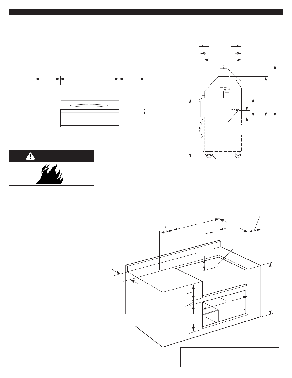
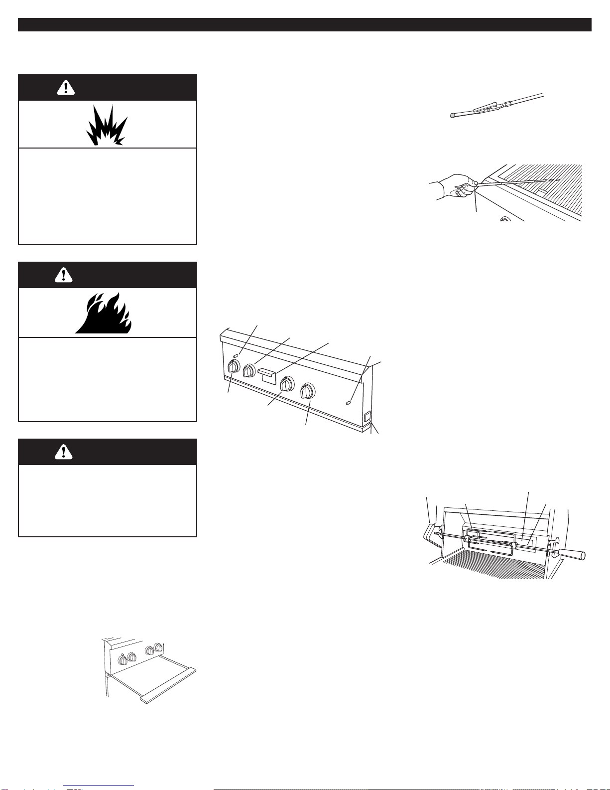
It is the responsibility of the installer to
comply with the minimum installation
clearances specified on the model/serial
rating plate.The model/serial rating plate
can be found on the heat shield behind
control panel, close to smoker box.
WARNING: If the information
in this manual is not followed
exactly, a fire causing death
or serious injury may occur.
2
Copies of the standards listed may be obtained
from:
National Fire Protection Association
One Batterymarch Park
Quincy, Massachusetts 02269
CSA International
8501 East Pleasant Valley Rd.
Cleveland, Ohio 44131-5575
This is the safety alert symbol.
This symbol alerts you to
potential hazards that can kill
or hurt you and others.
All safety messages will follow the
safety alert symbol and either the word
“DANGER” or “WARNING”.These
words mean:
FOR YOUR SAFETY
If you smell gas:
1. Shut off gas to the
appliance.
2. Extinguish any open flame.
3. Open lid.
4. If odor continues,
immediately call your gas
supplier or your fire
department.
FOR YOUR SAFETY
1. Do not store or use
gasoline or other
flammable vapors and
liquids in the vicinity of
this or any other appliance.
2. An L.P. cylinder not
connected for use shall not
be stored in the vicinity of
this or any other appliance.
IMPORTANT:
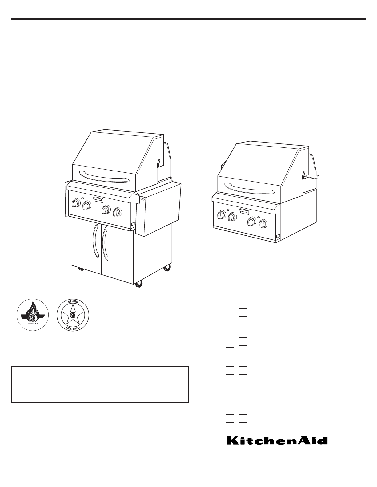
This grill is manufactured for
outdoor use only.
IMPORTANT SAFETY INSTRUCTIONS
If the following information is not
followed exactly, a fire causing death or
serious injury may occur.
• Do not store a spare LP-gas cylinder
under or near this grill.
• Never fill the cylinder beyond 80
percent full.
3
Tools and parts
needed for Built-in
(non-combustible
construction)
installations
Location
requirements
Parts supplied
• convertible regulator set for 4" W.C. natural
gas, 11" W.C. L.P. gas (attached to
manifold)
Parts needed
The portable grills are manufactured
for use with L.P./Propane gas.
To convert to Natural gas, Gas
Conversion Kit no. 4396311
must
be
used. Instructions included with kit.
• To connect to a fixed L.P./propane gas
supply, you must purchase Convertible
Regulator Kit No. 4396424 from your
dealer.
Parts needed
The built-in grills are manufactured for
use with natural gas.
To convert to L.P./propane gas, Gas
Conversion Kit no. 4396312 must be
used. Follow Instructions included with kit.
• level
• small flat-blade screwdriver
• flat-blade screwdriver
• Phillips screwdriver
• tape measure or ruler
• slip-joint pliers
• pipe wrench
• scissors or cutting pliers to remove
tiedowns
Materials required:
• gas line shutoff valve
• 1/2" male pipe thread nipple for connection
to pressure regulator
• L.P. gas-resistant pipe-joint compound
• AGA or CSA design-certified flexible
stainless steel appliance connector
[4-5 ft. (1.2-1.5 m)] or rigid gas supply line
as needed
• non-corrosive leak detection solution
Tools and parts
needed for Portable
installations
Parts supplied
• hose and regulator assembly set for 11"
W.C. L.P. gas (attached to manifold)
• 20 lb. L.P. tank (empty) – requires purging
and L.P. gas fill by certified L.P. gas fill
station
• level
• small flat-blade screwdriver
• flat-blade screwdriver
• Phillips screwdriver
• tape measure or ruler
• slip-joint pliers
• adjustable wrench
• scissors or cutting pliers to remove
tiedowns
Materials required:
• non-corrosive leak detection solution
Select a location
that provides minimum
exposure to wind and traffic paths.The
location should be away from strong draft
areas.
Do not obstruct flow of combustion and
ventilation air.
If you plan to use a
combustible enclosure,
return this unit and replace it with the
model which is manufactured for use in a
combustible enclosure.
Clearance to combustible construction
for built-in (non-combustible
construction) and portable grills:
A minimum of 12" (30.5 cm) must be
maintained between the grill hood, sides
and back and any combustible construction.
A 12" (30.5 cm) minimum clearance must
also be maintained below the cooking
surface and any combustible construction.
Rotisserie
If your model is equipped with a
rotisserie, 6" (15.2 cm) minimum
clearance on each end is needed for the
motor and skewer.
A grounded, 3-prong outlet located to the
left of the grill is required. (See “Electrical
requirements” section.)
WARNING
Fire Hazard
Do not use grill near combustible
materials.
Do not store combustible materials
near grill.
Doing so can result in death or fire.
WARNING
Explosion Hazard
Do not store fuel tank in a garage or
indoors.
Do not store grill with fuel tank in a
garage or indoors.
Failure to follow these instructions
can result in death, explosion, or fire.
The California Safe Drinking Water and
Toxic Enforcement Act requires the
Governor of California to publish a list
of substances known to the State of
California to cause cancer, birth defects,
or other reproductive harm, and
requires businesses to warn of potential
exposure to such substances.
WARNING: This product contains a
chemical known to the State of
California to cause cancer, birth defects,
or other reproductive harm.
This appliance can cause low-level
exposure to some of the substances
listed, including benzene, crystalline
silica, carbon monoxide, toluene, and
soot.
WARNING
Fire Hazard
Do not install this grill on or near
combustible materials.
Doing so can result in death or fire.
4
Product Dimensions
Built-in Installation
Dimensions
(non-combustible
enclosure)
36"
(91.4 cm)
portable
models
24-5/8"
(62.5 cm)
34"
(86.4 cm)
11-1/8"
(28.3 cm)
3-5/8"
(9.2 cm)
1/2"
male NPT
locking front
casters
side tray*side tray*
*Not all models have side trays.
23" (58.4 cm)
25-1/2" (64.8 cm)
26" (66.0 cm)
27" (68.6 cm), or
36" (91.4 cm)
Portable and Built-in models
Enclosure and clearance dimensions
that are
shown must be used. Given dimensions provide
required clearances.
The installation of this grill must conform with the
current standards CSA-Z21.58a-1998*, or with
local codes.
For installations in a
non-combustible
enclosure
, the grill drops into the opening and
is supported by its side flanges. Do not use a
bottom support.
Copies of the standards listed may
be obtained from:
*CSA International
8501 East Pleasant Valley Rd.
Cleveland, Ohio 44131-5575
A22"
(57.2 cm)
2-1/4"
(5.7 cm)
7-3/8"
(18.7 cm)
gas line
location at
rear of grill
6" (15.2 cm)
min. clearance
for rotisserie
12" (30.5 cm)
minimum to
any accessory
2" (5.1 cm)
minimum to
open hood
counter or support surfaces
must be level
10-7/8"
(27.0 cm)
19"
(48.3 cm)
35-1/2"
(90.2 cm)
1-1/8"
(2.9 cm)
Grill size A B
27" (68.6 cm) 26" (66.7 cm) 25-1/4" (64.1 cm)
36" (91.4 cm) 35" (89.5 cm) 34-1/4" (87.0 cm)
Non-combustible enclosure installations
12"
(30.5 cm)
12"
(30.5 cm)
Clearance to combustible construction for built-in (non-combustible construction) and portable grills:
A minimum of 12" (30.5 cm) must be maintained between the grill hood, sides and back and any combustible construction.
A 12" (30.5 cm) minimum clearance must also be maintained below the cooking surface and any combustible construction.
optional custom
access doors
B
WARNING
Fire Hazard
Do not install this grill on or near
combustible materials.
Doing so can result in death or fire.
5
Line pressure testing:
Testing above 1/2 psi (3.5 kPa) or
14 inches (35.5 cm) W.C. (gauge)
The grill and its individual shutoff valve
must be disconnected from the gas
supply piping system during any pressure
testing of that system at test pressures
greater than 1/2 psig (3.5 kPa).
Testing below 1/2 psi (3.5 kPa) or
14 inches (35.5 cm) W.C. (gauge) or
lower
The grill must be isolated from the gas
supply piping system by closing its
individual manual shutoff valve during any
pressure testing of the gas supply piping
system at test pressures equal to or less
than 1/2 psig (3.5 kPa).
Gas supply
requirements
Observe all governing codes and
ordinances.
Important: Grill must be connected to
a regulated gas supply.
•Input ratings shown on the model/serial
rating plate are for elevations up to 2,000
feet (610 m). For elevations above 2,000
feet (610 m), ratings are reduced at a
rate of 4% for each 1,000 feet (305 m)
above sea level. Orifice conversion is
required. Contact KitchenAid Assistance
Center.
•Refer to the model/serial rating plate for
information on the type of gas that can
be used. If this information does not
agree with the type of gas available,
check with your local gas supplier.
No attempt shall be made to convert
the grill from the gas specified on the
model/serial rating plate for use with a
different gas type without consulting the
serving gas supplier.The conversion
kits specified must be used.
Portable Grills
L.P. Gas:
This grill is equipped for use with a L.P.
gas fuel tank. It is design-certified by CSA
International for local L.P. gas supply or
for Natural gas with appropriate
conversion.
L.P. gas from a local L.P. gas supply:
IMPORTANT:
The gas installation must
conform with local codes, or in the
absence of local codes, with the National
Fuel Gas Code, ANSI Z223.1/NFPA 54.
The qualified L.P. gas technician shall
provide the L.P. gas supply to the
selected grill location in accordance with
the National Fuel Gas Code, NFPA 54
and local codes.
Natural gas conversion:
Conversion must be made by a qualified
gas technician.
The qualified natural gas
technician shall provide the natural gas
supply to the selected grill location in
accordance with the National Fuel Gas
Code NFPA 54 and local codes. For
conversion to Natural gas, the Natural
gas conversion kit must be used.
IMPORTANT:
The gas installation must
conform with local codes, or in the
absence of local codes, with the National
Fuel Gas Code, ANSI Z223.1/NFPA 54.
To convert to Natural gas, the Natural
Gas Conversion Kit No. 4396311 must be
used, Instructions are included with the
kit.
L.P. GAS:
Operating pressure:
11 inches (27.9 cm) W.C.
Supply pressure: 11 to 14 inches
(27.9 to 35.5 cm) W.C.
NATURAL GAS:
Set pressure 4 inches (10.2 cm) W.C.
Supply pressure 7-14 inches
17.8 cm to 35.5 cm) W.C. maximum.
L.P. gas conversion from a local L.P. gas
supply:
Conversion must be made by a qualified
gas technician.
The qualified natural gas
technician shall provide the L.P. gas
supply to the selected grill location in
accordance with the National Fuel Gas
Code NFPA 54 and local codes.To
convert to L.P. gas, the L.P. Gas
Conversion Kit No. 4396312 must be
used. Follow Instructions included with kit.
L.P. gas conversion using a L.P. fuel tank:
To convert to L.P. gas, the L.P. Gas
Conversion Kit No. 4396312 must be
used. Follow Instructions included with kit.
A L.P. gas cylinder, not larger than 20
pounds, must be purchased separately.
NATURAL GAS:
Set pressure 4 inches (10.2 cm) W.C.
Supply pressure 7-14 inches
17.8 cm to 35.5 cm) W.C. maximum.
L.P. GAS:
Operating pressure:
11 inches (27.9 cm) W.C.
Supply pressure: 11 to 14 inches
(27.9 to 35.5 cm) W.C.
to grill
shutoff valve
“open” position
gas supply
line
The supply line shall be equipped with an
approved shutoff valve.This valve should
be located in the same area as the grill
and should be in a location that allows
ease of opening and closing. Do not block
access to the shutoff valve.The valve is
for turning on or shutting off gas to the
appliance.
Built-in Grills –
non-combustible construction
Natural Gas:
Built-in grill models are equipped for use
with Natural gas.They are design-certified
by CSA International for L.P. (propane or
butane) gases with appropriate
conversion.
Built-in models are set for natural gas use
and have a pressure regulator with 1/2"
female pipe threads.
6
Rotisserie electrical
requirements
Electrical Shock Hazard
Plug into a grounded 3-prong outlet.
Do not remove ground prong.
Do not use an adapter.
Do not use an extension cord.
Failure to follow these instructions
can result in death, fire, or electrical
shock.
WARNING
If codes permit and a separate ground
wire is used, it is recommended that a
qualified electrician determine that the
ground path is adequate.
Check with a qualified electrician if
you are not sure whether the grill is
properly grounded.
Do not ground to a gas pipe.
A 120-volt, 60-Hz, AC-only, 15-ampere,
electrical supply is required.
Recommended ground method
A grounded 3-prong outdoor outlet
grounded in accordance with the National
Electrical Code ANSI/NFPA 70** or
Canadian Electrical Code (C22.1*) — and
local codes and ordinances.
Copies of the standards listed above may be
obtained from:
*CSA International
8501 East Pleasant Valley Rd.
Cleveland, Ohio 44131-5575
** National Fire Protection Association
One Batterymarch Park
Quincy, Massachusetts 02269
3-prong polarized
ground-type outdoor
outlet
power
supply cord
3-prong
ground plug
ground
prong
7
Installation
Instructions —
Portable Outdoor
Grill
Excessive Weight Hazard
Use two or more people to move
and install grill.
Failure to do so can result in back
or other injury.
WARNING
1.Move grill into desired outdoor
location.
2.Open the hood.
3.For models equipped with
rotisserie, remove the rotisserie’s skewer
from the grill.
4.Carefully lift off grill grates and set
aside.
sear plate
5.Remove sear plates and set aside.
burner
remove
tiedowns
6.Remove tiedowns from burners
and warming shelf.
7.Reinstall sear plates. Make sure
sear plates are resting on pins.
8.Open cabinet doors and remove
L.P./propane gas tank.
9.Make gas
connections.
L.P./propane
(supplied):The
20 lb. L.P. tank is
located in the
compartment below grill. Remove tank
and take to an authorized dealer to be
filled. Reinstall tank and screw the hose/
regulator assembly to tank as shown.
The pressure regulator and hose
assembly supplied with the grill must be
used. Replacement pressure regulator
and hose assembly specific to your
model, is available from your outdoor grill
dealer.
If converting to natural gas, see
conversion kit requirements and “Gas
supply requirements” section. Follow
instructions included with kit.
hose/regulator
assembly
10.Turn on the gas supply. Wait a
few minutes for gas to move through the
gas line.
Test for gas leaks.
Test all connections by brushing on an
approved non-corrosive leak-detection
solution. Bubbles will show a leak.
Correct any leak found.
11.Go to “Checking and adjusting
the burners” section.
warming
shelf
remove
tiedowns
pins
8
Installation
Instructions —
Built-In Outdoor
Grill
(non-combustible
construction)
1.Place grill into outdoor enclosure,
but leave enough room in back to connect
to gas supply.
2.Make gas connections.
A combination of pipe fittings must be
used to connect the grill to the existing
gas line.
This installation must conform with local
codes and ordinances**. In the absence of
local codes, installations must conform
with either the National Fuel Gas Code
ANSI Z223.1, or CAN/CGA-B149.1*
Natural Gas and Propane installation code.
sear plate
7.Remove sear plates and set aside.
burner
remove
tiedowns
8.Remove tiedowns from burners
and warming shelf.
warming
shelf
remove
tiedowns
Excessive Weight Hazard
Use two or more people to move
and install grill.
Failure to do so can result in back
or other injury.
WARNING
Natural Gas Use
4.Open the hood.
5.For models equipped with
rotisserie, remove the rotisserie’s
skewer from the grill.
6.Carefully lift grill grates off of grill
area and set aside.
valve open
IMPORTANT: If grill is to be installed in a
combustible enclosure, return this unit
and replace it with the model which is
manufactured for use in a combustible
enclosure.
rear of
grill
1/2" grill
gas pipe
hole in
rear panel
flexible gas
connector
3.Open shutoff valve in the gas supply
line.The valve is open when the handle is
parallel to the gas pipe.
Test for gas leaks.
Test all connections by brushing on an
approved non-corrosive leak-detection
solution. Bubbles will show a leak. Correct
any leak found.
•If local codes permit, use a flexible
stainless steel tubing gas connector,
design-certified by AGA or CSA
International, to connect the grill to the
rigid gas supply line. 5/8" diameter line is
recommended. Using a wrench to
tighten, connect the gas supply to the
grill. Use pipe joint compound on all non-
flared male threads. Do not kink or
damage the flexible connector when
moving the grill.
• Pipe-joint compounds suitable for use
with L.P. gas must be used. Do not use
Teflon®tape.
valve closed
®Teflon is a registered trademark of E.I. Du Pont
de Nemours and Company.
WARNING
Fire Hazard
Do not use grill near combustible
materials.
Do not store combustible materials
near grill.
Doing so can result in death or fire.
WARNING
Fire Hazard
Do not install this grill on or near
combustible materials.
Doing so can result in death or fire.
Copies of the standards listed may
be obtained from:
*CSA International
8501 East Pleasant Valley Rd.
Cleveland, Ohio 44131-5575
** for local codes, contact your local
building inspector
Low flame adjustment:
If flame goes out on the “LO” setting, the
low flame setting must be adjusted.
1.
Turn off the valve and wait until grill
and burners are cool.
2.
Remove grill grates, sear plates.
3.
Light grill using information in the
“Lighting the grill” section.
4.
Turn burner to its lowest setting and
remove knob.
5.
Hold valve stem with pliers and insert a
thin flat-blade screwdriver into the shaft.
6.
Watch the flame and slowly turn the
screwdriver counter-clockwise.
7.
Adjust flame to minimum stable flame.
8.
Replace the control knob and turn off
the burner.
9.
Repeat Steps 3 through 8 for each
burner if needed.
10.
Replace the sear plates and grates
after the burners have cooled.
5.
Remove burner and loosen air shutter
adjustment screw.
a.
If flame is yellow (not enough air),
turn air shutter counter-clockwise.
b.
If flame is noisy or lifts away from
burner (too much air), turn air
shutter clockwise.
Adjustment should be from
1/8" to 1/4".
6.
Tighten air shutter adjustment screw.
7.
Replace burner sear plates and grates.
8.
Ignite burner to check flames. See
“Sear burner flame characteristics.”
Repeat Steps 1 through 8 above if
needed.
Only adjust the burners that need
adjustment.
9
Adjusting the air shutters:
1.
Light grill using information in the
“Lighting the grill” section.
2.
Observe flame to determine which
burners need adjustment and how the
flame is acting. See “Sear burner flame
characteristics” above.
3.
Turn off the valve and wait until grill
and burners are cool.
4.
Remove grill grates, sear plates.
air shutter
adjustment screw
Checking and
adjusting the
burners
The burners are tested and factory-set for
most efficient operation. However,
variations in gas supply and other
conditions may make minor adjustments
to air shutter or low flame setting
necessary. Adjustments must be done by
a qualified service technician.
NOTE: No adjustment can be made to the
infrared rotisserie burner (not used on all
models) or smoker tray burner(s).
Checking and adjusting the grill burner
flames requires removing the grate and
sear plates.
Sear burner flame characteristics:
The flames of the grill burners and
surface burners (not used on all models)
should be blue and stable with no
excessive noise or lifting (L.P./propane
gas flames will have a slightly yellow tip).
A yellow flame indicates not enough air. If
flame is noisy or lifts away from the
burner, there is too much air. Some
yellow tips on flames when the burner is
set to HI setting are acceptable as long as
no carbon or soot deposits appear.
9.Reinstall sear plates. Make sure
sear plates are resting on pins.
10.Carefully slide grill completely
into outdoor enclosure.
11.Now go to the "Checking and
Adjusting Burners Section."
pins
valve stem
Check that burners are not blocked by
dirt, debris, insect nests, etc. and clean
as necessary. If they are clean, adjust air
shutters as needed.
IMPORTANT:
Before adjusting air
shutters, let burners cool down.
10
Using the rotisserie
For best cooking results, do not use main
grill burners when using the rotisserie.
The rotisserie system is designed to cook
food from the rear using intense, searing
infrared heat.
1. Remove warming shelf.
2. Mount rotisserie motor on the grill's
mounting bracket. Position it securely
into support bracket slots.
3.To load the spit rod, slide one of the
rotisserie forks onto the spit rod with
prongs facing away from handle.
rotisserie
fork
motor
spit rod
back infrared burner
IMPORTANT:
Light only one burner at a
time.
1. Do not lean over burners. Push in and
turn to "LITE" the control knob for the
burner you wish to use.
2. Push in the burner ignitor button.You
will hear the “snapping” sound of the
spark. Keep the burner ignitor button
pushed in until burner lights. Make sure
burner is lit. Repeat for each of the
other burners as needed.
IMPORTANT:
If burner does not light immediately, turn the
burner knob to “OFF” and wait 5 minutes
before relighting.
infrared
burner
control
knob
smoker
tray
smoker tray
burner
control knob
grill burner
control knob
grill burner
control knob ignitor battery
compartment
red button
burner
igniter
button
Grill Use
Using your Grill
Prepare the gas supply
1. Open the hood completely. Do not light
burners with the hood closed.
2. Make sure
control knobs are
turned to OFF.
The drip pan
must be in place
and pushed all
the way to the
back.
WARNING
Fire Hazard
Do not use grill near combustible
materials.
Do not store combustible materials
near grill.
Doing so can result in death or fire.
WARNING
Explosion Hazard
Do not store fuel tank in a garage
or indoors.
Do not store grill with fuel tank in a
garage or indoors.
Failure to follow these instructions
can result in death, explosion, or fire.
Food Poisoning Hazard
Do not let food sit for more than
one hour before or after cooking.
Doing so can result in food
poisoning or sickness.
WARNING
3.
Turn the gas supply on:
• For portable grills using an L.P./
propane gas cylinder:
Slowly open the cylinder valve; do not
“snap” open.
NOTE:
If flow limiting device does
activate, your grill may not light. If
your grill does light, the flames will be
low and will not heat properly.Turn
cylinder valve and all control knobs
off and wait 30 seconds. After
shutting off the cylinder, very slowly
open cylinder valve and wait 5
seconds before lighting.
• For grills using gas supply source
other than L.P. gas cylinder:
Turn the shut off valve to open position
from the front of gas supply line.
Manually lighting main grill burners
1. Remove the manual lighting extension
from inside the drip tray.
2. Attach a match to the clip.
3. Strike the match to light it.
4. Carefully guide the lit match between
the grill grate and one of the slots in
the sear plate.
5. Push in and turn the burner knob to
“LITE” for the burner closest to the lit
match.The burner will light immediately.
6. Repeat steps 2 through 5 for each
main burner.
7. Replace manual lighting extension
inside the drip tray.
IMPORTANT:
If burner does not light immediately, turn the
burner knob to “OFF” and wait 5 minutes
before relighting.
If any burners do not light after attempting
to manually light them, contact the
KitchenAid Assistance Center.
Lighting the grill
drip pan