Range Hood - 36" (91.4 cm) and 48" (121.9 cm)
PRODUCT MODEL NUMBERS
KXW9736Y KXW9748Y
Because Whirlpool Corporation policy includes a continuous commitment to improve
our products, we reserve the right to change materials and specifications without notice. Dimensions are for planning purposes only. For complete details, see Installation
Instructions packed with product. Specifications subject to change without notice. Ref. W10331009C
1/31/2012
CABINET OPENING DIMENSIONS
IMPORTANT:
Minimum distance “X”: 24" (61 cm) from electric cooking surfaces
Minimum distance “X”: 30" (76.2 cm) from gas cooking surfaces
The chimneys can be adjusted for different ceiling heights. See the
following chart.
Vented Installations
Min. ceiling height Max. ceiling height
Electric cooking surface 7' 9" (2.36 m) 10' 2" (3.1 m)
Gas cooking surface 8' 3" (2.51 m) 10' 2" (3.1 m)
*NOTE: The range hood chimneys are adjustable and designed to meet
varying ceiling or soffit heights depending on the distance “X”
between the bottom of the range hood and the cooking surface. For
higher ceilings, an Extension Kit Part Number W10352733 is
available from your dealer or an authorized parts distributor. The
chimney extension replaces the upper chimney shipped with the range
hood.
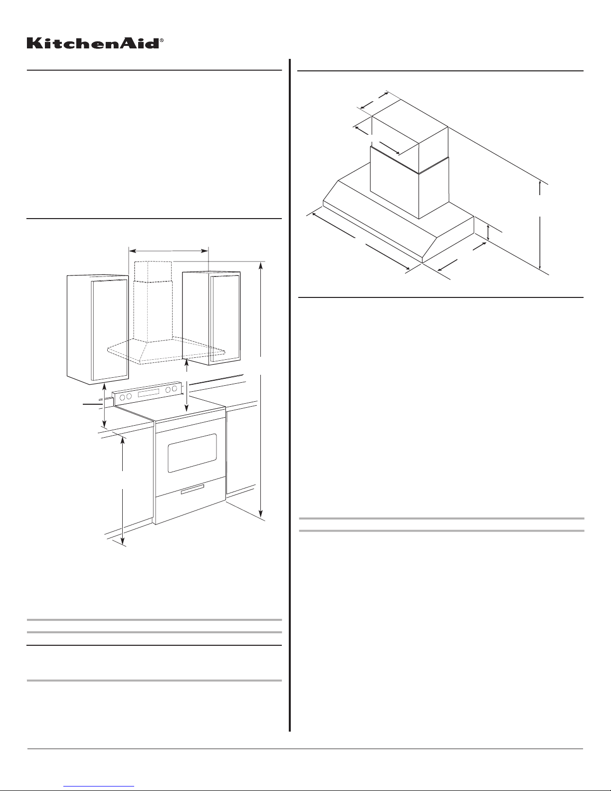
PRODUCT DIMENSIONS
Vented Installations
36" (91.4 cm)
or 48" (121.9 cm) 25" (63.5 cm)
7⁷⁄₈"(20.0 cm)
11⁵⁄₁₆" (28.7 cm)
32³⁄₈" (82.2 cm) min.
50¹¹⁄₁₆" (128.7 cm) max.
22³⁄₄"(57.8 cm)
VENTING REQUIREMENTS
Page 1 of 2
Electrical Requirements:
● A 120 volt, 60 Hz., AC only, 15-amp, fused electrical circuit is
required.
● If the house has aluminum wiring, follow the procedure below:
1. Connect a section of solid copper wire to the pigtail
leads.
2. Connect the aluminum wiring to the added section
of copper wire using special connectors and/or
tools designed and UL listed for joining copper to
aluminum.
Follow the electrical connector manufacturer's recommended
procedure. Aluminum/copper connection must conform with local
codes and industry accepted wiring practices.
18" (45.7 cm) min.
clearance upper
cabinet to countertop
X*
36" (91.4 cm)
countertop height
See Note*
36" (91.4 cm) or 48" (121.9 cm)
or cabinet opening width
(if installed between cabinets)
● Vent system must terminate to the outdoors.
● Do not terminate the vent system in an attic or other enclosed area.
● Do not use 4" (10.2 cm) laundry-type wall caps.
● Use metal vent only. Rigid metal vent is recommended. Plastic or metal foil
vent is not recommended.
● The length of vent system and number of elbows should be kept to a
minimum to provide efficient performance.
For the most efficient and quiet operation:
● Use no more than three 90° elbows.
● Make sure there is a minimum of 24" (61.0 cm) of straight vent between the
elbows if more than 1 elbow is used.
● Do not install 2 elbows together.
● Use clamps to seal all joints in the vent system.
● The vent system must have a damper. If the roof or wall cap has a damper,
do not use the damper supplied with the range hood.
● Use caulking to seal exterior wall or roof opening around the cap.
● The size of the vent should be uniform.
Venting Methods
Typical Internal Blower Motor System Venting Installations
A 10" (25.4 cm) round vent system is needed for installation (not included).
The range hood exhaust opening is 10" (25.4 cm) round.
NOTE: Flexible vent is not recommended. Flexible vent creates back pressure
and air turbulence that greatly reduce performance.


 36\" (91.4 cm) 48\" (121.9 cm) Wall-Mount Canopy Range... User manual")


 COMMERCIAL STYLE WALL-MOUNT CANOPY RANGE... Product information sheet")


