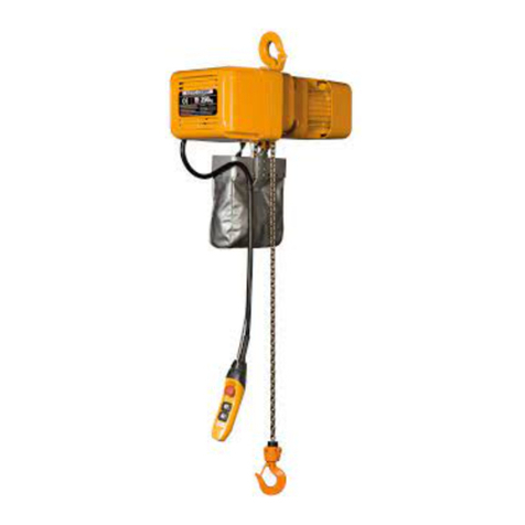
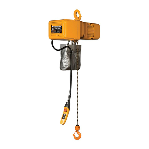
KITO ER2 Series Configuration guide

1
OM-ER2CZZ-MGE-00
ER2 Cylinder Control Electric Chain
Hoist (125 ㎏& 250 ㎏)
SUPPLEMENTARY OWNER'S MANUAL
Hook Suspension: ER2C
With Plain Trolley:
ER2CSP

2
Introduction
The Cylinder Control Electric Chain Hoist is best-suited for the operation of traveling a smaller
load over a shorter path by operating the grip of the cylinder control integrated with the bottom
hook attaching to the end of the load chain. Before use, please read and comply with the
instructions in this Owner’s Manual.
Safety Precautions
CAUTION
This Owner's Manual describes specific information regarding the Cylinder Control
Electric Chain Hoist (125kg & 250kg). Before use, read and comply with both the
ER2 Series Electric Chain Hoist (125kg to 5t) Owner's Manual and this manual.
At the time of unpackage, make records of the Product (serial) No. and the specific
for upcoming inspection with reference to the ER2 Series Electric Chain Hoist
(125kg to 5t) Owner's Manual.
Product Specifications & Operating Conditions
Product Specifications
Short time rating: 60 minutes for single speed, 30/10 minutes for dual speed
Percent ED: 60%ED for single speed, 40/20%ED for dual speed
Class: Class: Single speed model : M5 Dual speed VFD model (high speed / low speed) : M6
Protection class: IP44
Standard Lift: 1.8m
The product specifications other than listed above is the same as a standard hoist. Please refer to the
section of "Product Specifications" in "ER2 Series Electric Chain Hoist (125kg to 5t) Owner's Manual"
(separate volume).
For the operating conditions, please also refer to the ER2 Series Electric Chain Hoist (125kg to 5t)
Owner's Manual, and for the dimensions, refer to the Appendix in this manual.
CAUTION
As the precision parts are inside the cylinder switch, do not use the hoist under an
environment where a lot of oil, dust or moisture are present. Always keep the switch
clean with a periodical check.
Failure to follow this precaution may cause mal-function,serious injury or property
damage.

3
Rated load
Product code
Hoist
body
Hook suspension With plain trolley
Single speed Dual speed
inverter Single speed Dual speed
inverter
125 ㎏ER2-B ER2C001H ER2C001IH ER2CSP001H ER2CSP001IH
250 ㎏ER2C003S ER2C003IS ER2CSP003IS ER2CSP003IS
Configurations & Name
Hook
suspension
Plain trolley
Cable support
Curl cord
Movable grip
Grip
Emergency
stop button
Load chain
Cord holder
Bottom hook
Hook attachmen
Cylinder switch

4
Assembly
When some parts may not be pre-installed depending on the specifications of your order, please
properly attach them in accordance with the following instructions.
Attachment of Top Hook (or Suspender)
1) Remove the Shaft Retainer Clip using plier.
2) Remove Socket Bolt from the Shaft Retainer, and remove the Shaft Retainer.
3) Remove two Connection Shafts.
4) Remove the Top Hook and replace it with the Connection Yoke.
5) Insert two Connection Shafts into the hole of the Body size.
6) Mount the Shaft Retainer with Socket Bolt.
Attachment of Stopper & Cushion Rubber
Insert the load chain into the cushion rubber at both chain ends and then fix the stopper at the
following chain link with the socket bolts.
On the load side, 32nd link from the end of the load
chain
On the no-load side, 3rd link from the end of the
load chain
Attachment of Cylinder Switch to Load Chain
Attach the load chain to the cylinder switch on the
top of the cord holder with the chain pin, slotted
nut, and split pin.
Top hook
Suspender
Split pin
Slotted
nut
Connection
bolt
Connection
yoke
Shaft Retainer clip
Connection
Shaft
Shaft
Retainer
Socket bolt
Chain pin Split pin
Slotted nut
Cord holder
Socket bolt
Cushion rubber No-load side
Load
side
Stopper

5
Operations
Lifting and Lowering Load
While holding the stationary grip of the cylinder switch,
move the movable grip of the switch up and down by
using the thumb and index finger.
To lift, move up the movable grip.
To lower: move down the movable grip
Shifting Speed (Dual-speed Inverter)
The selector switch can shift the speed between
high and low in the dual speed inverter hoist.
Low-speed
Pressing the selector switch to the right sets the
low-speed to turn on the green lamp (LED).
High-speed
Pressing the selector switch to the left sets the
high-speed to turn on the red lamp (LED).
Emergency Stop
In case of equipment failure and other unexpected danger, the emergency stop can stop lifting
or lowering operation.
To make emergency stop, press the red button on the side of the cord holder.
To release emergency stop, turn the pressed button to the right (in the arrowed direction as
shown above)
Resetting Inverter (for Dual-speed Inverter hoist)
In dual-speed inverter hoist, overload or overcurrent may trip the inverter. In the case of the
inverter being tripped, press the emergency stop button to reset the inverter because the
emergency stop also brings the inverter to a reset
DANGER
Make sure that the split pin is securely bent.
Make sure that the stopper and cushion rubber are attached to the correct chain link.
Failure to follow these precautions may cause serious accidents leading to serious or
even fatal injury.
UP: Lifting
DOWN: Lowering
Stationary grip
Movable grip
Cylinder switch
(How to hold the grip)
High-speed:
LED (red)
Low-speed:
LED (green)
Emergency stop
button
Selector switch
C
ord holder

6
Attaching & Detaching Bottom Hook
To attach
Insert the bottom hook into the underside of the hook
attachment.
To detach
Turn the section A to the left as shown in the picture on
the right.
Adjustable Speeds of Dual-speed Inverter
In the dual-speed inverter, the low and high speeds can be adjustable by changing the inverter
parameters. Make sure that these parameters are properly set in accordance with the KITO ER2
Series Electric Chain Hoist (125kg to 5t) Owner's Manual as well as the KITO ER2 Series Electric
Chain Hoist (125kg to 5t) Inverter Manual.
DANGER
Do not make excessive operations (inching, plucking), which may cause failure.
Do not stop moving a suspended load by pressing the emergency stop button while
the hoist is in the normal operation.
Do not handle the hook attachment while a load is suspended. (Do not detach the
bottom hook.)
After the bottom hook is attached, make sure that the hook does not come off from the
hook attachment.
Failure to follow these precautions may cause serious accidents leading to serious or
even fatal injury.
Hook attachment
A
(Attachment) (Detachment)

7
Daily Inspection
DANGER
Perform daily inspection before use.
(In case that an irregular arises during the inspection, de-energize the main power, post a
notice of out-of-order and request maintenance personnel for repair.)
Failure to perform daily inspection may cause serious accidents leading to serious or
even fatal injury.
For the inspection items other than the followings, refer to the KITO ER2 Series Electric Chain
Hoist (125kg to 5t) Owner's Manual.
Item Method Criteria Action
Appearance Visual (1) Should be no adverse scar, crack, or
damage on each section of the cylinder
switch.
Replace damaged
parts.
(2) Should be no adverse scar or crack on
the curl cord.
(3) The curl cord should not drop off. Securely fix the curl
cord using a binding
band.
(4) The warning label should not peel. Replace the warning
label or securely stick
it.
(5) Should be no loose or missing bolt,
nut, split pin, hook attachment, or
bottom hook.
(The bottom hook does not come off
even by pulling it lightly.)
Secure them.
(6) Should be no dirt or foreign
substance on the cylinder switch. Clean it.
Cylinder switch
operation Operation (1) The movable grip should properly
move Contact your dealer or
KITO for consultation.
(2) The hoist should smoothly operate
without an intermittent move.
(3) Should be not abnormal sound or
vibration.
(4) The selector switch should make a
smooth shift in speed.
Periodic Inspection
Monthly Inspection / Annual Inspection
DANGER
After completion of
monthly
or
annual inspection,
make sure that the hoist
properly works by performing functional check and test.
Failure to perform monthly inspection may cause serious accidents leading to serious or
even fatal injury.

8
For the inspection items other than the followings, refer to the KITO ER2 Series Electric Chain Hoist
(125kg to 5t) Owner's Manual for the items corresponding to your hoist capacity.
Chain pin
Item Method Criteria Action
Deformation,
scar, wear Visual
Measured by
using a slide
caliper
Should be no remarkable deformation or scar.
The amount of wear on engagement with the
load chain should not exceed 5%.
Replace the
chain pin.
Cylinder switch
Item Method Criteria Action
Plate screw Visual check
Fastening Should neither loose nor missing.
The hook attachment should not rotate.
(Should be no significant gap between the grip
and the hook attachment.)
Securely fasten
the plate screw.
Troubleshooting
For the inspection items other than the followings, refer to the KITO ER2 Series Electric Chain Hoist
(125kg to 5t) Owner's Manual for the items corresponding to your hoist capacity.
Cylinder switch
Symptom
Fail
ure
section Main cause Remedy
Hoist will not
operate even
by using the
movable grip.
Failure of
switches
inside the
cylinder
(1) Dust or foreign substance inside
the cylinder
(2) Electric leakage or rust caused
by water inside switches
(3) Service life of contact in internal
switches exceeded
Micro switch service life
Mechanical: 1,000,000 times
Electrical: 30,000 times
(4) Damage caused by excessive
operation
Replace damaged
parts.
Cleaning
Hoist will
operate in a
direction
different from
the movable
grip motion
Mal-wiring - Rewire properly in
accordance with
the wiring diagram.
(Refer to pages 11
and 12.)
Notice
At the time of monthly or annual inspection, also perform daily inspection.
Gap
Grip
Hook
attachment
Plate screw

9
Appendix
Technical Data
Hook Suspension
[Specifications]
Capacity
(kg) Product
code Hoist
body
Standard
lift
(m)
Lifting motor Lifting speed (m/s) Load
chain
Class *Weight
(kg)
Additional
weight
per
1m lift
(kg)
Output
(kW)Rating
%ED 50Hz 60Hz
Diameter
(mm)
Chain falls
125 ER2C001H
B 1.8 0.56
60 - 0.235 0.282
4.3×1
M5 30
0.42
250 ER2C003S - 0.152 0.182 30
125 ER2C001IH
40/20
Preset 0.277 0.0461
M6
29
Adjustable 0.277 0.0231
250 ER2C003IS Preset 0.179 0.0299 29
Adjustable 0.179 0.0150
* Weight for 1.8m lift.
[Dimensions (mm)]
Capacity
(kg)Product code
Minimum
headroom
C
D a b d e fg h i
125 ER2C001H
1010 430
478
(564) 321
(345) 219
(305) 259
260
(284) 27 99
93
(117)
250 ER2C003S
125 ER2C001IH 535
(564) 345 276
(305) 284 117
250 ER2C003IS
Note : Figures in ( ) are date for mechanical brake with friction clutch.
Lift

10
With Plain Trolley Suspension
[Specifications]
Capacity
(kg) Product
code Hoist
body
Standard
lift
(m)
Lifting motor Lifting speed (m/s) Applicable
beam
width
B
(mm)
Min.
radius
curve
(mm)
Load
chain
Class *Weight
(kg)
Additional
weight
per
1m lift
(kg)
Output
(kW)Rating
%ED 50Hz 60Hz
Diameter
(mm)
Chain
falls
125 ER2CSP00
1H
B 1.8
0.56 60 - 0.235 0.282
[50]
75
100 1100 4.3 x 1
M5 34
0.42
250 ER2CSP00
3S 0.152 0.182 34
125 ER2CSP00
1IH 0.56 40/20
Preset 0.277 0.0461
M6
33
Adjusta
ble 0.277 0.0231
250 ER2CSP00
3IS
Preset 0.179 0.0299 33
Adjusta
ble 0.179 0.0150
* Weight is for 1.8m lift.
[Dimensions (mm)]
Capacity
(kg)Product code
Minimum
headroom
C
D a b e g h i j k m n o p q r t
125 ER2CSP001H
1050 470 204 182 46 27 82 60 21 76 47.5 84 42 10 54 38 22
250 ER2CSP003S
125 ER2CSP001IH
250 ER2CSP003IS
Lift

11
Wiring Diagrams
Single speed - ER2C001H/003S, ER2CSP001H/003IS
Description
Transformer
Fuse
Electromagnetic brake
CH meter
Rectifier
Lifting
/lowering motor
8
-plug socket
4
-plug socket
Device Code
Remarks
1.
Speed
Chain hoist: single speed
2.
Voltage: 200V 50/60Hz, 220V 60Hz
3.
Plug-socket connection
ElectricChainHoist
(Upper
limit)
(Lower
limit)
Red = R
White = W
Black = BLK
Orange
= O
Brown = BR
Gray = GY
Green/Yellow
= G/Y
R
R
W
W
BLK
BLK
RWOGY
GY
UpDown
R
BLK
G/Y
Emer-
gency
stop
GY
W
BR
BLK
W
R
W
BRBR
R
W
BLK
G/Y
R
W
BLK
G/Y
BLK
R
W
O
G/Y
BLK
R
W
O
G/Y
Emergency stop
Up
Down
(Up) (Up)
(Down)(Down)
Single-speed
cylinder
(Single-stage) (Dual-stage)
(Single-stage) (Dual-stage)

12
Dual-speed Inverter - ER2C001IH/003IS, ER2CSP001IH/003IS
Description
Transformer
Fuse
Electromagnetic brake
Inverter
Rectifier
Lifting
/lowering motor
ER2
interfaceboard
Braking resistor
Device Code
Remarks
1.
Speed
Chain hoist: dual speed (inverter)
2.
Voltage: 200V 50/60Hz, 220V 60Hz
3.
Plug-socket connection
Red = R
White = W
Black = BLK
Orange
= O
Brown = BR
Gray = GY
Green/Yellow
= G/Y
Blue = BL
8
-plug socket
4
-plug socket
(Upper limit)
(Lower limit)
R
W
R
W
W W
W
BRBR
G/Y
BLKR
BLK
R
BR
W
O
GY
BLK
R
BL
W
O
GY
G/Y
G/Y
R
W
BLK
G/Y
R
W
BLK
G/Y
Emergency stop
(Up)
Dual-speed cylinder
Electric Chain Hoist
Up
Down
(Up)
(Down)
(Down)
(Single-stage) (Dual-stage)
(Single-stage) (Dual-stage)
(R)
(G)
(High-speed)
(Low-
speed) (High-
speed)
(Low-
speed)

《MEMO》

Global Website:kito.com
Other manuals for ER2 Series
4
Table of contents
Other KITO Lifting System manuals
Popular Lifting System manuals by other brands
SAFWAY
SAFWAY Spider Relevation SC1000 Operator's manual

TRIUMPH BOARD
TRIUMPH BOARD LiftBox manual
Ravaglioli
Ravaglioli KPX341 Translation of the original instructions
Howard
Howard M9 Technical & service manual
Bishamon
Bishamon Lift2K Service and operation manual
HEEVE
HEEVE DRIVEWAY RUBBER KERB RAMP installation guide
Aqua Creek Products
Aqua Creek Products F-03EZPLNA Installation, assembly and operation manual
AMGO
AMGO MC-1200 Installation and service manual
Anthony Liftgates
Anthony Liftgates MTU-GLR Series Maintenance manual
Blue Giant
Blue Giant BLUE GENIUS TL85 Series Installation & owner's manual

Denios
Denios XH manual
Zenit
Zenit blueBOX manual
