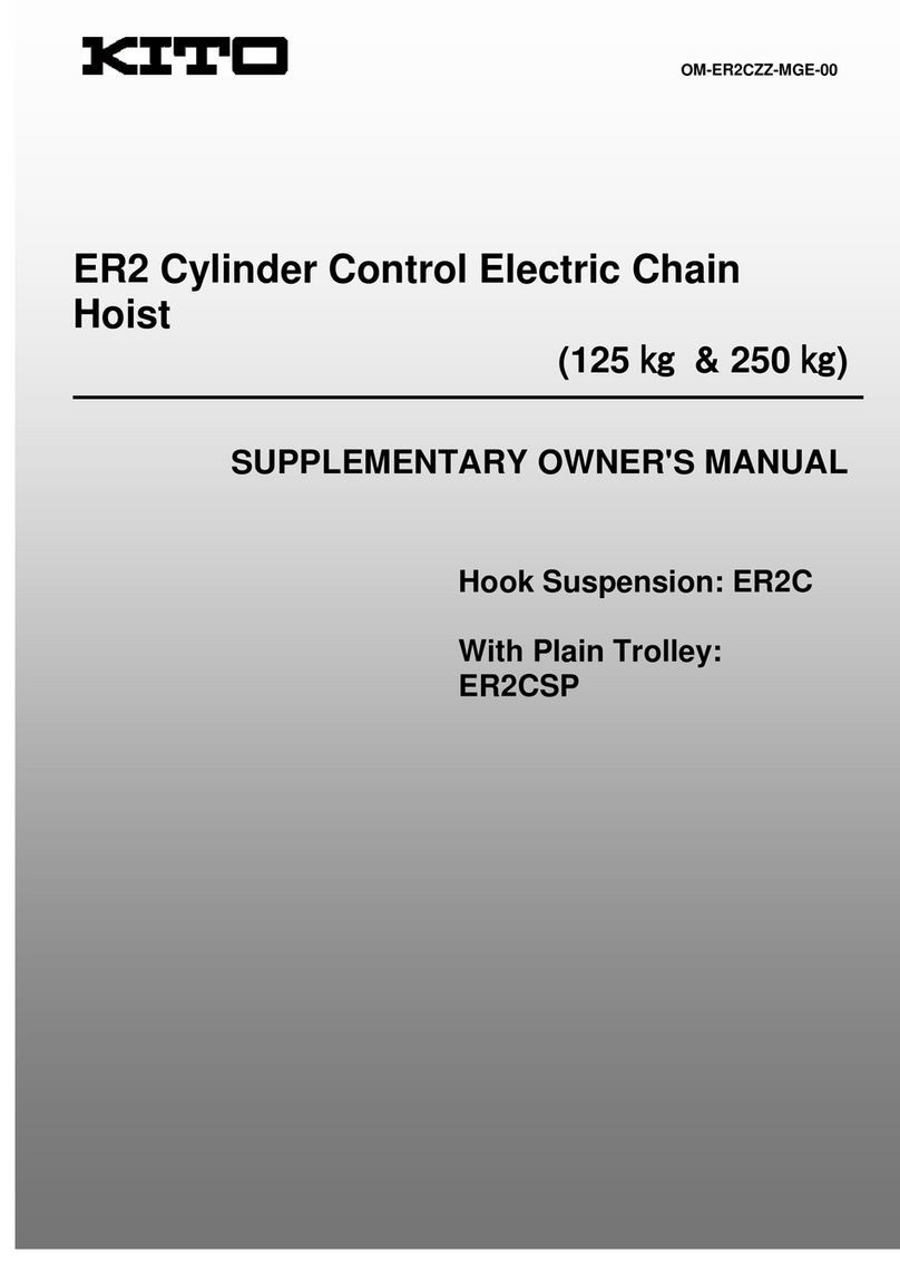
KITO ER2-075S Configuration guide

OM-ER2LZZ-MGE-00
To Customer
This manual contains specific information related to large capacity models. Before use, please read and comply
with all the contents of the "ER2 Series Electric Chain Hoist (125kg to 5t) Owner's Manual" (separate publication) as
well as this manual to ensure proper use of the products.
Suspended with
Hook : ER2
Motorized Trolley : ER2M
Manual Trolley : ER2SP/ER2SG
Supplementary Manual
ER2 Series Electric Chain Hoist (7.5t to 20t)
Owner's Manual

2
Safety Precautions
Table of Contents
CAUTION
This owner’s Manual provides specific information regarding the ER2 electric chain hoist (7.5t to 20t). Before operating the
product, be sure to read and comply with all the contents of both this Manual and the ER2 Series Electric Chain Hoist (125kg
to 5t) Owner’s Manual to operate the product correctly.
Safety Precautions .........................................................................................................2
Product Specication and Operational Environment .................................................3
Standard Specications• .....................................................................................3
Operational Environment• ...................................................................................5
Nameplate and Product Code .......................................................................................6
Nameplate of Electric Chain Hoist• ....................................................................6
Nameplate of Motorized Trolley• .........................................................................7
Nameplate of Manual Trolley• .............................................................................7
Product Code of Large Capacity• .......................................................................7
Checks on Unpacking ...................................................................................................8
Checking Chain Stamps• .....................................................................................8
Recording the Product No• .................................................................................8
Recording the Initial Value• .................................................................................8
Assembling .....................................................................................................................9
Installing a Chain Container• ..............................................................................9
Checking Power and Power Cable• ..................................................................13
Connecting Cables• ...........................................................................................15
Regular inspection .......................................................................................................20
Daily Inspection• ................................................................................................20
Frequent Inspection• .........................................................................................21
Periodic Inspection• ...........................................................................................23
Appendix .......................................................................................................................27
Specication and Dimension of Large Capacity• ............................................27
Wiring Diagram• .................................................................................................30
Mandatory

3
Product Specifications and Operational Environment
Standard Specifications
■
Short-time rating : ER2 (100% of rated load) - 60 minutes,
MR2 (100% of rated load) - 30 minutes
Intermittent rating : ER2 (63% of rated load) - 60% ED, MR2 (63% of rated load) - 40% ED
Hoist classification * : ISO-M4,FEM-2m,ASME-H4
Protection : Hoist IP55,Push Button Switch IP65
Push button control : 3-push button control for hook or manual trolley suspension, / 5 or 7-push button control for
motorized trolley suspension
Lift : 3m (standard)
Power supply method : Cabtyre cable
Color : KITO Yellow (Equivalent to Munsell 7.2YR6.5/14.5)
Braking capacity : 150% or more
Applicable rail type : I beam, H beam
Applicable rail width : 150mm – 308mm
Power supply cable : Standard length - 10m
Voltage & motor :
Voltage category Motor Insulation
Class
Voltage range Control
Voltage
50Hz 60Hz
230V Class B 220V 220V
24V
(24V~27.8V)
230V 230V
400V Class F
380V 380V
400V 440V
415V —
500V Class B 500V 575V
230/460V Class B 208-230V 110V
(110V~121V)
415-460V
* For more information about the operating conditions and environment, refer to the ER2 Series Electric Chain Hoist
(125kg to 5t) Owner’s Manual, and for the standard dimensions refer to the appendixes in this manual.
The operational environment of the electric chain hoist and motorized trolley is as follows:
NOTE
Operate the electric chain hoist at the rated voltage.•
Do not use the electric chain hoist beyond the short time and intermittent ratings.•
* Hoist classification
Capacity (t) Code ISO ASME FEM
7.5 ER2-075S
M4 H4 1Am
10 ER2-100L
ER2-100S
15 ER2-150S
20 ER2-200S
Product Specications and Operational Environment
Standard Specications

4
ISO 4301 specifies the total operating hour (service life) of gears and bearings according to the loading status. For
example, the total operating hour (service life) of the mechanism for M5 constantly subjected to the rated load is
1,600 hours. The total operating hour reaches 6,300 hours under a medium load.
*Rate of loading
Light : A case where the capacity is rarely applied. Usually the hoist is used with a light load.
Medium : A case where the capacity is applied considerably frequently. Usually the hoist is used with a medium
load.
Heavy : A case where the capacity is applied considerably frequently. Usually the hoist is used with a heavy load.
Ultra heavy : A case where the capacity is applied constantly.
Loading status Total operating hour h
800 1600 3200 6300 12500
Light M4 M5
Medium M4 M5
Heavy M4 M5
Ultra heavy M4 M5
ISO
●
Hoist duty class Typical areas of application
Operation time ratings at K=0.65
Unlformly distributed
work periods
Infrequent
work periods
Max. on
time, min / hr
Max. No.
starts / hr
Max. on time from
cold start, min
Max. No.
of starts
H2
Light machine shop fabricating,
service,and maintenance; loads and
utilization randomly distributed; capacitys
infrequently handled.
7.6 (12.5%) 75 15 100
H3
General machine shop fabricating,
assembly, storage, and warehousing;
loads and utilization randomly distributed.
15 (25%) 150 30 200
H4
High volume handing in steel warehouses,
machine shops, fabricationg plants and
mills, and foundries; manual or automatic
cycling operations in heat treating
and plating; loads at or near capacity
frequently handled.
30 (50%) 300 30 300
ASME HST
●
The grade symbols are identical to those of ASME HST-1M. (Performance standard for Electric Chain Hoist)•
Relation between ISO-and FEM-Denominations
1 Dm 1 Cm 1 Bm 1 Am 2 m 3 m 4 m 5 m
M 1 M 2 M 3 M 4 M 5 M 6 M 7 M 8
Load
spectrum
Cubic
mean value
Class of operation time
V0.06 V0.02 V0.25 V0.5 V1 V2 V3 V4 V5
T0 T1 T2 T3 T4 T5 T6 T7 T8
Average operation time per day in hours
0.12 0.25 0.5 1 2 4 8 16 >16
1 L1 K 0.50 – – 1 Dm 1 Cm 1 Bm 1 Am 2 m 3 m 4 m
2 L2 0.50<K 0.63 – 1 Dm 1 Cm 1 Bm 1 Am 2 m 3 m 4 m 5 m
3 L3 0.63<K 0.80 1 Dm 1 Cm 1 Bm 1 Am 2 m 3 m 4 m 5 m –
4 L4 0.80<K 1.00 1 Cm 1 Bm 1 Am 2 m 3 m 4 m 5 m – –
Class of
operating
time
Average
operating
time per day
(in hours)
Calculated
total operating
time
(in hours)
V0.06 T0 0.12 200
V0.12 T1 0.25 400
V0.25 T2 0.5 800
V0.5 T3 1 1,600
V1 T4 2 3,200
V2 T5 4 6,300
V3 T6 8 12,500
V4 T7 16 25,000
V5 T8 >16 50,000
FEM
●
The grade symbols are identical to those of FEM 9.511.•
(Rules for Design of Serial Lifting Equipment: Classification of Mechanisms)
Product Specications and Operational Environment
Standard Specications

5
Operational Environment
■
Ambient temperature : -20°C to +40°C
Slope of rail : No slope of travelling rail (for the hoist with trolley)
Ambient humidity : 85 % or less (no condensation)
Explosion-proof construction : Not applicable to the work environment with explosive gases or explosive vapor
Environment to be avoided : A place with organic solvent or volatile powder, and a place with a plenty of powder
and dust of general substances
: A place with considerable amount of acids and salts
NOTE
When installing the electric chain hoist outdoors or to the place where the hoist is exposed to direct rain, wind and snow,
shelter the hoist under a roof to protect it from rain, wind and snow.
Product Specications and Operational Environment
Operational Environment

6
Nameplate of Electric Chain Hoist
■
CODE: ER2-100S
CHAIN SIZE: T-11.2×31.2mm
LOT No: MFG.YEAR
SERIAL No:
LIFTING SPEED: 0.118 m/s 50Hz
: 0.142 m/s 60Hz
SIZE: ER2-F GRADE: M4
②③
④
⑤⑦
⑥
⑧
⑨
①
1· · · Capacity Ex. 10t
The maximum mass of the load that can be
imposed on the product. The mass of the hook is
excluded.
2SIZE · · · Body size Ex. Body size F, ER2-F
The size of the electric chain hoist body to
support the load. Five models of B, C, D, E and F
are provided.
3GRADE Ex. M4
The grade of an electric chain hoist specified
by Japanese Industrial Standard JIS indicates
degree of durability.
4CODE · · · Product code Ex. ER2-100S
The code is denotations composed of product
model, capacity, lifting speed.
5CHAIN SIZE · · · Load Chain size
Ex. T-11.2×31.2mm
The alphabet and the figures indicate the JIS
grade, wire diameter and chain pitch respectively.
6LOT No.
Manufacture No. to identify the time of manufacture
and a batch of production.
7MFG. YEAR · · · Manufacture year
8SERIAL No.
Serial number to indicate the manufacturing sequence
of the product.
9LIFTING SPEED
Nameplate and Product Code
Nameplate and Product CodeNameplate of Electric Chain Hoist

7
Nameplate of Motorized Trolley
■
LOT No:
SERIAL No:
TRAVELING SPEED:
0.333 m/s 50Hz
0.400 m/s 60Hz
CODE: MR2-100L MFG.YEAR
①②
④
⑤
⑥
③
1· · · Capacity Ex. 10t
The maximum mass of the load that can be
imposed on the product. The mass of the hook is
excluded.
2CODE · · · Product code Ex. MR2-100L
The code is denotations composed of product
model, capacity, lifting speed.
3MFG. YEAR · · · Manufacture year
4LOT No.
Manufacture No. to identify the time of manufacture
and the quantity of a production unit.
Nameplate of Manual Trolley
■
Product code of large capacity
■
1· · · Capacity Ex. 10t
The maximum mass of the load that can be imposed
on the product. The mass of the hook is excluded.
2LOT No.
Manufacture No. to identify the time of manufacture
and the quantity of a production unit.
3SERIAL No.
Serial number to indicate the manufacturing sequence
of the product.
①
②
③
5SERIAL No.
Serial number to indicate the manufacturing
sequence of the product.
6TRAVELING SPEED
Capacity
Code
Electric chain hoist Motorized trolley Manual trolley
(geared trolley)
Body size Standard speed Low speed Low speed
7.5t
ER2-F
ER2-075S -MR2-075L TSG075
10t ER2-100S ER2-100L MR2-100L TSG100
15t ER2-150S -MR2-150L TSG150
20t ER2-200S -MR2-200L TSG200
Nameplate and Product Code Nameplate of Motorized Trolley / Nameplate of Manual Trolley

8
Checks on Unpacking
Capacity Load Chain : diameter
(mm) Stamp interval
7.5t
11.2 12 links
10t
15t
20t
RH-DAT 0000 RH-DAT
Stamp interval
First stampSecond stamp Second stamp
Front side : RH-DAT
or FT-DAT
Back side : H-23
Front side : Lot No. of the Load Chain
(4 digits)
Back side : KITO
After unpacking, confirm chain stamp, and make a record of serial number and an inspection as shown below.
Be sure to check that the Load Chain is for the electric chain hoist ER2. The Load Chain of other models •
(such as model ES or ER) or for different capacity cannot be used.
Failure to use a proper chain may result in death or serious injury due to the drop of the lifted load.
Mandatory
Mandatory
The load chain identification stamp (RH-DAT) is indicated on at intervals of chain links. Make sure that the Load
Chain is of a chain size (wire diameter) appropriate for ER2 referring to the table below.
DANGER
DANGER
Fill in the table in the right with product's Lot
●
No., Serial No. (described in the product
nameplate), date of purchase and the name
of the sales shop where you purchased the
product.
* When requesting repair or ordering a hoist
part, please inform us of these pieces of
information together.
Item
Electric chain hoist
Motorized trolley Manual trolley
Lot No. ER2A– MR2A– TS2–
Serial No.
Date of purchase
Name of the sales shop
Checking Chain Stamps
■
Checks on Unpacking
Checking Chain Stamps / Recording the Product No. / Recording the Initial Value
Recording the Product No.
■
Recording the Initial Value
■
For later maintenance or inspection, at the
●
time of unpacking, fill in the table in the right
with the dimension "a" between embossed
marks on the Bottom Hook, the width of the
hook "b" and the thickness of the hook "c".
(These values are used for checking. Please
also record the value for the top hook of ER2
when your product is suspended with a hook.)
Initial dimensions
b
c
a
Embossed marks
Top Hook
(For ER2 only)
Dimension a mm
Dimension b mm
Dimension c mm
Bottom Hook
Dimension a mm
Dimension b mm
Dimension c mm

9
The each type of Chain Container has the capacity to store the specific amount of the Load Chain. Use the •
Chain Container in correct capacity.
An chain overflow from the overstored container or a drop of container improperly installed on the hoist can cause
quite dangerous situation, resulting in fatal or serious injury.
Failure to have the maintenance personnel install the Chain Container may cause fatal or serious injury.
Before installation of the container, please also check the container capacity of the hoist and lifting height as shown
on the container.
Mandatory
Assembling
Only qualified maintenance personnel or experts are allowed to assemble and disassemble the electric chain •
hoist.
Assembly or disassembly of the hoist by incompetent personnel may result in death or serious injury.
Prohibited
Installing a Chain Container
■
Preparation for Assembling
■
To facilitate mounting the chain container, hang the hoist body.•
Check that the stopper and the cushion rubber are attached to the third link from the end of the no-load side chain•
(the side without the Bottom Hook).
Assembling
■
The two types of the Chain Container are provided: canvas and steel
This manual describes the method to combine the canvas Chain Container with the body of the electric chain hoist.
Refer to the separate “Mounting Manual of the Steel Chain Container" for the steel Chain Container.
When storing the Load Chain into the Chain Container, put the end of no-load side chain first and then store •
the rest of the Load Chain in order.
Failure to comply with these instructions may causes bodily injury or loss of property.
Mandatory
CAUTION
DANGER
DANGER
Chain Container Seal
●
A seal in the right to indicate the hoist capacity and the
maximum lift is attached to the Chain Container. Be sure to
check it before installation.
Assembling Installing a Chain Container

10
7.5t, 10t(L)
●
10t(S), 15t(S), 20t(S)
●
1) Install 2 container chains to the chain
container with socket bolts, plain
washers, and lever nuts.
2) Install the lug of the container on the
chain guide A at the bottom of the hoist
with the bolts and lever nuts.
3) Install 2 container chains to the
container suspender with the socket
bolts, plain washers and lever nuts.
1) Install 2 container chains to the chain
container with socket bolts, plain
washers, and lever nuts.
2) Install the lug of the container on the
chain guide A at the bottom of the hoist
with the bolts and lever nuts.
3) Insert the socket bolt through a plate of
the Connection yoke, both end links of
container chains and the other plate and
fasten them with plain washers and lever
nuts.
Container
suspension wheel
Socket bolt
Plain washer
Container chain
Socket bolt
Plain washer
Chain container
Connection Yoke
Lever nut
Socket bolt
Container chain
Lever nut
Socket bolt
Plain washer
Chain container
Fix with bolt
and lever nut.
Fix with bolt
and lever nut.
Lever nut
Lever nut
AssemblingInstalling a Chain Container

11
Checking rails used for the trolley, and adjusting the collar
■
Although the product is shipped in conjunction as far as the order of the hoist and trolley is made, it is necessary to
adjust the collars to the width of your rail. When a rail width is specified upon order, the collars arrangement is made
at shipment. However, if you change to a different rail width, make correct collar adjustments as explained in this
section.
Rail and wheel profile
●
In the conjunction with the motorized or manual trolley, the profile of
the trolley wheel and the rail should meet. Check the profile of both
the rail and the wheel.
Rail spacer arrangement
■
Improper spacer arrangement could result in missing, irregular running or dropping. Make correct adjustments of the
trolley spacers to the rail width as shown in the following the table.
Motorized Trolley
●
Number of Adjusting Spacers
WLL (t)
Beam
flange
width
Parts
(mm) 149
150 153 155 160 163 170 175 178 180
181
184
185
200 203
215
220 229
232
250 254
257
260
264
267 279
283 286
289
295 298
300
302 305
7.5
to
20
Thin spacer
Inner
1+1 1+2 1+2 2+3 3+3 4+4 1+1 1+2 2+2 2+3 1+1 1+2 3+3 4+4 1+1 1+2 4+4 1+1 1+2 2+2 2+3 3+3 1+1 1+2 2+2 2+3 3+4 4+0 4+0 4+1 5+1
Outer
6553206543652065065432654314432
Thick spacer
Inner
1+1 1+1 1+1 1+1 1+1 1+1 2+2 2+2 2+2 2+2 3+3 3+3 3+3 3+3 1+1 1+1 1+1 2+2 2+2 2+2 2+2 2+2 3+3 3+3 3+3 3+3 3+3 3+4 3+4 3+4 3+4
Outer
4444442222000055533333111110000
Fixing spacer
Inner
- - - - - - - - - - - - - - 2 2 2 2 2 2 2 2 2 2 2 2 2 2 2 2 2
Remarks: (1) Take note the numbers on spacers of inner side as follows.
Example 0+1
0 : Number on side plate S
1 : Number on side plate G
(2) Adjustment of trolley width :
Adjust the dimensions by appropriately increasing or decreasing the number of inner or outer
adjusting spacers, without strictly adhering to the number of adjusting spacers shown in the above
table.
(3) Spacers arrangement example.
Number of Adjusting Spacers
For I beam For H beam
Inner
Side plate S
Suspension shaft
Outer
Suspender T
Fixing spacer
Side plate G
Thin spacer
Thick spacer
edisthgiRedistfeL
Assembling Installing a Chain Container

12
Manual Trolley
●
Same as the Motorized Trolley table.
AssemblingInstalling a Chain Container

13
Hook (ER2) and Manual Trolley (ER2SG) mount
●
Code Cable size
(mm2)
Capacity of fuse and circuit breaker (A)
200V class 400V class 500V class Cable size
(AWG)
230/460V
Single speed Single speed
-ER2SG075S 220 15 10 AWG14 30/10
-ER2SG100L
ER2-100S ER2SG100S
840 30 15 AWG10 50/20ER2-150S ER2SG150S
ER2-200S ER2SG200S
Motorized Trolley (ER2M) mount
●
Code Cable size
(mm2)
Capacity of fuse and circuit breaker (A)
200V class 400V class 500V class Cable size
(AWG)
230/460V
Single speed ER Single MR Single
ER2M075S-L 3.5 30 20 20 AWG12 30/15
ER2M100L- L
ER2M100S-L
860 40 20 AWG10 60/30ER2M150S-L
ER2M200S-L
Checking Power and Power Cable
■
Check that the source voltage meets the rated voltage of the electric chain hoist.•
Check that the rating of the breaker meets the specifications of the electric chain hoist.•

Failure to comply with this instruction may result in death or serious injury.
Mandatory
DANGER
Assembling Checking Power and Power Cable

14
Checking the Power Cable
●
Prohibited
Mandatory
CAUTION
Code
Cable
size
(mm2)
200V class 400V class 500V class 230/460V
Single speed Cable
size
(mm2)
Single speed
50Hz 60Hz 50Hz 60Hz 50Hz 60Hz
220-230V 220-230V 380-415V 380-440V 208-230V 415-460V
-ER2SG075S 2
(3.5)
21
(37)
18
(32)
59
(103)
56
(99)
108
(189)
AWG14
(AWG12)
16
(28)
68
(119)
-ER2SG100L
ER2-100S ER2SG100S 8
(14)
42
(75)
37
(64)
118
(207)
113
(198)
216
(378)
AWG10
(AWG8)
22
(32)
93
(136)
ER2-150S ER2SG150S
ER2-200S ER2SG200S
Code
Cable
size
(mm2)
200V class 400V class 500V class 230/460V
Single speed Cable
size
(mm2)
ER Single-MR Single
50Hz 60Hz 50Hz 60Hz 50Hz 60Hz
220-230V 220-230V 380-415V 380-440V 208-230V 415-460V
ER2M075S-L 3.5
(5.5)
27
(42)
24
(38)
71
(111)
71
(112)
138
(217)
AWG12
(AWG10)
21
(34)
90
(142)
ER2M100L- L
ER2M100S-L 8
(14)
36
(63)
32
(56)
96
(169)
95
(166)
182
(319) AWG10
(AWG8)
19
(28)
80
(117)
ER2M150S-L 31
(54)
28
(49)
81
(142)
82
(143)
158
(276)
17
(25)
71
(103)
ER2M200S-L
NOTE) Figures in parentheses ( ) mean the cable one size larger than the standard size.
Do not use the cable other than the accompanying cable or optional power cable.•
Failure to comply with this instruction causes bodily injury or loss of property.
Do not use the power supply cables beyond their maximum length or cable size.•
Failure to comply with this instruction causes bodily injury or loss of property.
AssemblingChecking Power and Power Cable

15
NOTE
Do not fastening the cable plugs by using a tool and be sure to fasten them by hand.•
Tightening excessively a connector may result in damaging or breaking plastic threads.
To prevent the cable from disconnecting or coming off, secure the strain relief wire of the push button cord to the hoist or •
trolley body.
Connecting Cables
■
Be sure to turn off the power supply before wiring work.•
Failure to comply with this instruction causes fatal or serious injury due to electrical shock.
Mandatory
DANGER
Relay cable
for operation Connection box Cable holder arm
Cable holder
Holder B
Power cable
Holder A
Cable packing
Cord chain stopper
Protection wire
Pan head screw
Electric chain
hoist
Electric chain
hoist
Relay cable
for power
Relay cable for
operation
Socket (8P)
Socket holder
Lock ring
Plug (8P)
Socket (4P)
Plug (4P)
Lock ring
Plug (8P)
Socket (8P)
Relay cable
for power
Hook Suspensions for 10t (S) or more
■
Assembling Connecting Cables

16
2) Insert the plugs (8P) of the relay cable for operation into the sockets (8P) of each of 2
hoists, and securely tighten the lock rings.
1) Insert the plugs (4P) of the relay cable for power into the sockets (4P) of each of 2 hoists,
and securely tighten the lock rings.
Connecting the relay cable
●
2) Insert the cord chain stopper into the end ring of the protection wire, and fix the stopper to
the socket holder with a pan head screw.
1)
Insert the plug (8P) of the push button swtich cord into the socket (8P), and securely tighten the
lock ring.
Connecting the push button switch cord
●
2) Remove the cable packing from the power cable, and pass holder A through the power
cable.
1) Remove holder A installed on the connection box.
Connecting the power cable
●
3) Pass the cable packing through the power cable (see the figure P15), and then insert it
into the connection box.
4) Tighten holder A, and fix the power cable to the connection box.
5) Connect the power cable to the terminal panel in the connection box.
(Refer to the wiring diagram on the connection box to perform wiring correctly.)
6) Fix the cable holder on the power cable to the cable holder arm.
AssemblingConnecting Cables

17
Motorized Trolley
■
Relay cable
for operation Connection box
Holder B
Power cable
Holder A
Cable packing
Cord chain stopper
Protection wire
Pan head screw
Electric chain hoist
Joining plate
Cord-support wire stopper
Protection wire
Pan head screw
Cable holder arm
Chain hanging pin B
Split pin
Slotted nut
Power cable
Cable
holder
Electric chain hoist
Relay cable for power
Relay cable for operation
Socket (8P)
Socket holder
Lock ring
Plug (8P)
Socket (4P)
Joining plate
Pan head screw
Cord-support wire
stopper
Protection wire
Plug (4P)
Lock ring
Plug (8P)
Socket (8P)
Relay cable
for power
<15t-20t Push Button Switch Cord> <Trolley Power Cable Connection>
Holder nut Plate D
Holder B
Holder A
<Direct-mount Push Button Switch Cord Connection>
Assembling Connecting Cables

18
1)
Remove holder A installed on the connection box.
2) Remove the cable packing from the power supply cable, and pass holder A through the power
cable.
3) Pass the cable packing through the power cable (see the figure P17), and then insert it into the
connection box.
4) Tighten holder A, and fix the power cable to the connection box.
Trolley Type
●
1) Mount the cable holder, which the Power Cable is passed, to the cable holder arm using a chain
hanging pin B, a slotted nut and a split pin.
5) Connect the power cable to the terminal panel on the connection box.
(Refer to the wiring diagram on the connection box to perform wiring correctly.)
6) Fix the cable holder on the power cable to the cable holder arm.
Connecting the power cable
●
1)
Insert the plugs (4P) of the relay cable for power into the sockets (4P) of each of 2 hoists, and
securely tighten the lock rings.
2) Insert the plugs (8P) of the relay cable for operation into the sockets (8P) of each of 2 hoists,
and securely tighten the lock rings.
1)
Insert the plug (8P) of the push button swtich cord into the socket (8P), and securely tighten
the lock ring.
2) Insert the cord chain stopper into the end ring of the protection wire, and fix the stopper to the
socket holder with a pan head screw. For 15t and 20t, fix the cord-support wire stopper to the
joining plate with a pan head screw.
Connecting the relay cable
●
Connecting the push button switch cord
●
Direct-mount
●
1) Mount the Holder B, which the Push Button Switch Cord is passed, to the plate D using the
holder nut.
2) Connect the Push Button Switch Cord to the terminal panel of the Connection Box.
AssemblingConnecting Cables

19
Cable holder Cable holder arm
Connector Socket holder
Plug (8P)
Socket (8P)
Cord Support L
Pan head screw
Protection wire
Lock Ring
Plug (4P)
Pan head
screw
Socket (4P)
Cable Support L
Manual Trolley Type (7.5t, 10t(L))
■
2) Fix the power cable to the cable holder with a affordable length.
1) Insert the plugs (4P) of the power cable into the sockets (4P) of each of 2 hoists, and
securely tighten the lock rings.
Connecting the push button switch cord
●
Connecting the power cable
●
1) Insert the plug (8P) of the push button swtich cord into the socket (8P), and securely
tighten the lock ring.
2) Insert the cord support L into the end ring of the protection wire and set the wire to
the notch of the cord support L, and fix the cord support L to the hoist body with a pan
head screw.
Direct connection
■
Cable Packing Connector Socket holder
Holder A
Holder A
Holder C (upper side)
Holder C (lower side)
1
2
2) Connecting the Push Button Cord
Insert the Push Button Cord into the Holder C
(lower side) of the Connector Socket holder.
Turn the Holder A to connect the cord securely.
3) Carry out wiring correctly in accordance with
the wiring diagram inside the Controller Cover.
1) Connecting the Power Cable
Insert the Power Cable into the Holder C (upper
side) of the Connector Socket holder. Turn the
Holder A to connect the cable securely.
* Items other than the above are the same to those
described for Plug Connection.
Assembling Connecting Cables

20
Regular Inspection
Carry out daily inspection before operation.•
(When any abnormality is found during inspection, turn off the power, indicate “FAILURE" and ask the maintenance
engineer for repair.)
Failure to comply with this instruction causes fatal or serious injury.
Mandatory
DANGER
For information about the items not shown in the following table, see the ER2 Series Electric Chain Hoist
(125kg to 5t) Owner’s Manual and perform the inspection.
Load chain
■
Daily Inspection
■
Hook, Idle Sheave
■
Item Check method Criteria When failed
Paint marks
on load chain
(except for
7.5t/10t – (L))
Check visually.•No misalignment in position•
(Misalignment between upper and lower of
paint marks must be within 1m.)
* Some misalignment due to differences in
hoisting/lowering speed and stop distance
between the left and right electric chain blocks
is not a fault.
With no load, lower the
chains until both limit
switches are triggered.
Item Check method Criteria When failed
Tilt of bottom
hook
Tilt of idle
sheave
Check visually and by•
operation.
No tilt•
Smooth rotation of the idle sheave and no tilt in•
bottom hook when hoisting/lowering
Move the load chain
or bottom fixture to
remove accidental
rotation, catching, and
twisting.
Paint marks
Regular InspectionDaily Inspection
This manual suits for next models
4
Table of contents
Other KITO Lifting System manuals