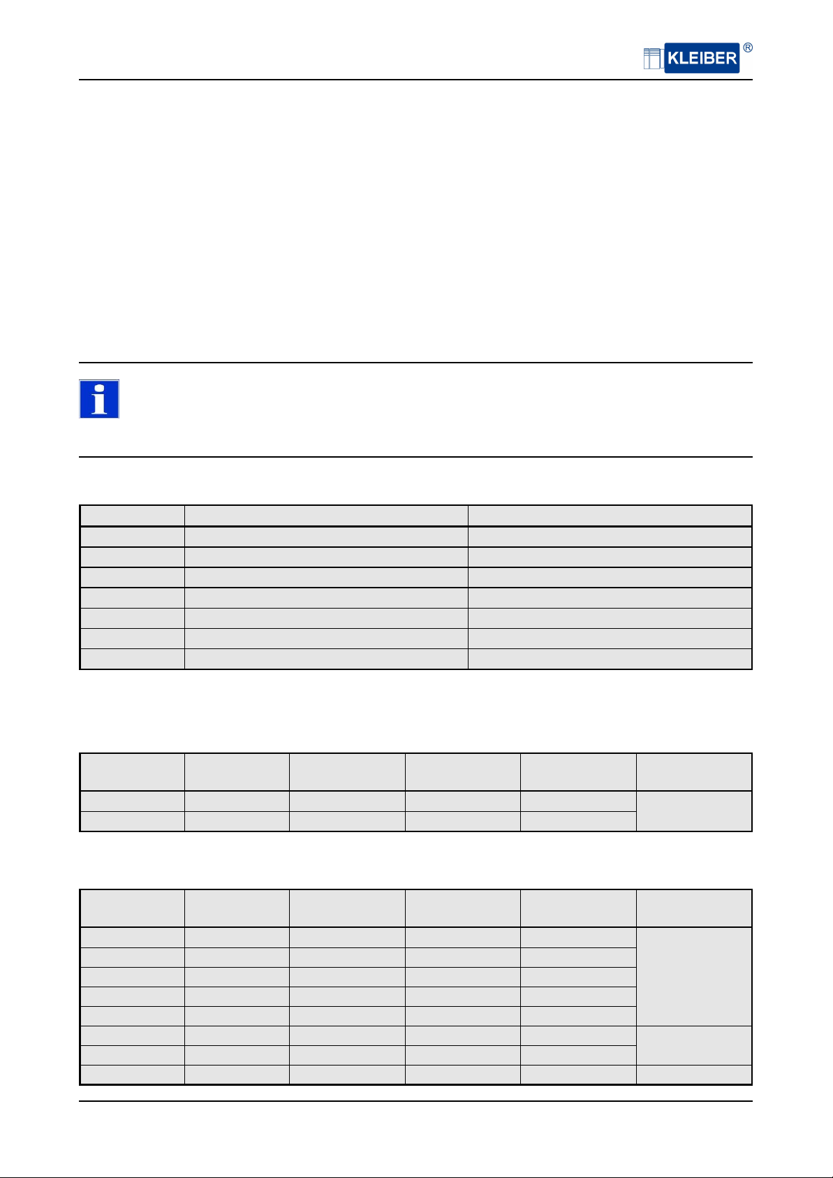
3 Scope of Delivery / Accessories
Fibre optics cable
Art.-No. Description
30005-14015 Fibre optics cable 400 𝜇m, blue, stainless steel, 1.5 m
30005-14020 Fibre optics cable 400 𝜇m, blue, stainless steel, 2.0 m
30005-14025 Fibre optics cable 400 𝜇m, blue, stainless steel, 2.5 m
30005-14050 Fibre optics cable 400 𝜇m, blue, stainless steel, 5.0 m
30005-14075 Fibre optics cable 400 𝜇m, blue, stainless steel, 7.5 m
30005-14100 Fibre optics cable 400 𝜇m, blue, stainless steel, 10.0 m
30005-14150 Fibre optics cable 400 𝜇m, blue, stainless steel, 15.0 m
30005-14900 Extension fibre optics cable 400 𝜇m, blue, stainless steel, per meter
30005-04015 Fibre optics cable 400 𝜇m, blue, PTFE, 1.5 m
30005-04020 Fibre optics cable 400 𝜇m, blue, PTFE, 2.0 m
30005-04025 Fibre optics cable 400 𝜇m, blue, PTFE, 2.5 m
30005-04050 Fibre optics cable 400 𝜇m, blue, PTFE, 5.0 m
30005-04075 Fibre optics cable 400 𝜇m, blue, PTFE, 7.5 m
30005-04100 Fibre optics cable 400 𝜇m, blue, PTFE, 10.0 m
30005-04150 Fibre optics cable 400 𝜇m, blue, PTFE, 15.0 m
30005-04900 Extension fibre optics cable 400 𝜇m, blue, PTFE, per meter
30005-12015 Fibre optics cable 200 𝜇m, red, stainless steel, 1.5 m
30005-12020 Fibre optics cable 200 𝜇m, red, stainless steel, 2.0 m
30005-12025 Fibre optics cable 200 𝜇m, red, stainless steel, 2.5 m
30005-12050 Fibre optics cable 200 𝜇m, red, stainless steel, 5.0 m
30005-12075 Fibre optics cable 200 𝜇m, red, stainless steel, 7.5 m
30005-12100 Fibre optics cable 200 𝜇m, red, stainless steel, 10.0 m
30005-12150 Fibre optics cable 200 𝜇m, red, stainless steel, 15.0 m
30005-12900 Extension fibre optics cable 200 𝜇m, red, stainless steel, per meter
30005-02015 Fibre optics cable 200 𝜇m, red, PTFE, 1.5 m
30005-02020 Fibre optics cable 200 𝜇m, red, PTFE, 2.0 m
30005-02025 Fibre optics cable 200 𝜇m, red, PTFE, 2.5 m
30005-02050 Fibre optics cable 200 𝜇m, red, PTFE, 5.0 m
30005-02075 Fibre optics cable 200 𝜇m, red, PTFE, 7.5 m
30005-02100 Fibre optics cable 200 𝜇m, red, PTFE, 10.0 m
30005-02150 Fibre optics cable 200 𝜇m, red, PTFE, 15.0 m
30005-02900 Extension fibre optics cable 200 𝜇m, red, PTFE, per meter
30005-22020 Fibre optics cable with vacuum lead 200𝜇m, stainless steel, length in vacuum 1 m, outside
1 m
30005-24020 Fibre optics cable with vacuum lead 400𝜇m, stainless steel, length in vacuum 1 m, outside
1 m
On request we manufacture other customers specific optical fibre cables with vacuum lead.
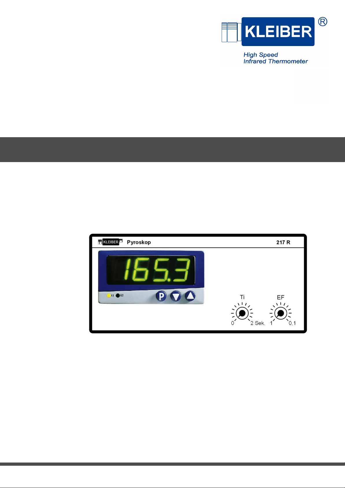
KLEIBER 217 R - LWL 5