7
OPERATING INSTRUCTIONS
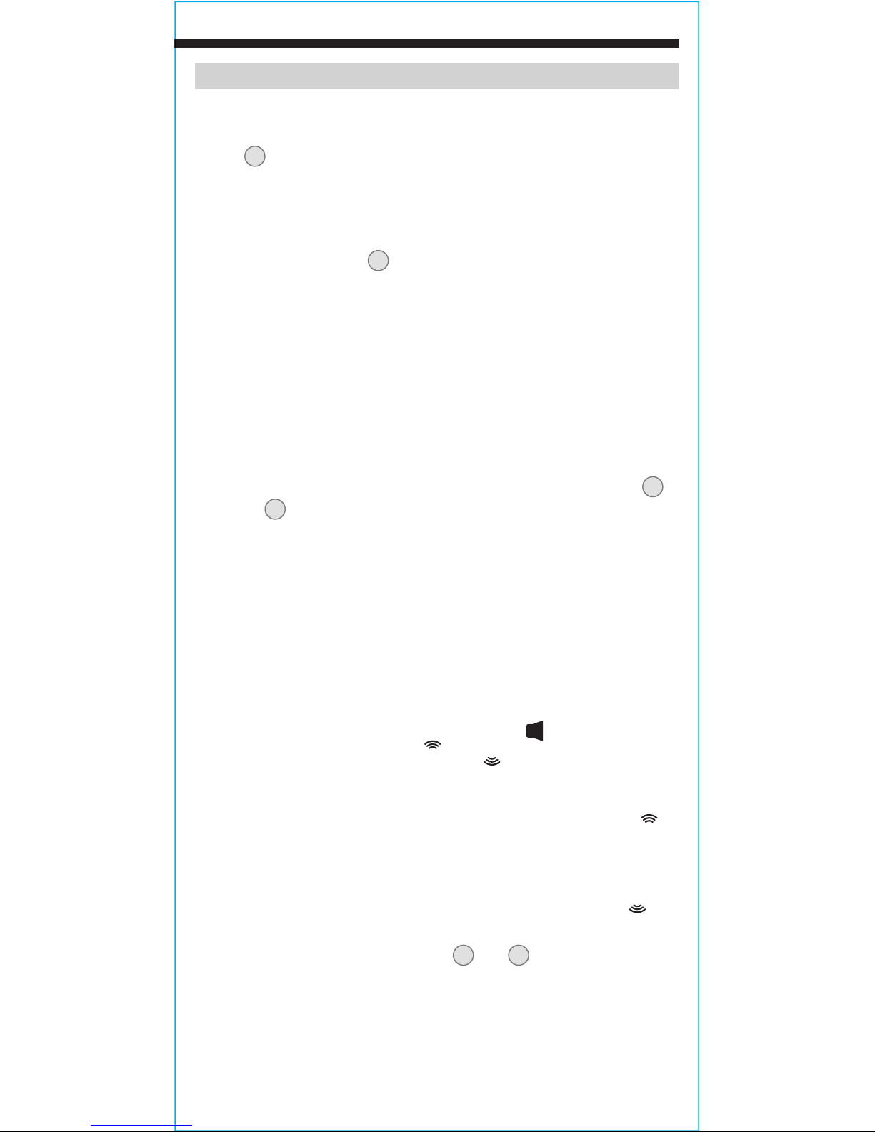
BACKLIGHT
The backlight may be toggled on/off by short presses of control
button
3
. When on, the backlight icon will be visible on the display.
MODE SELECTIONS
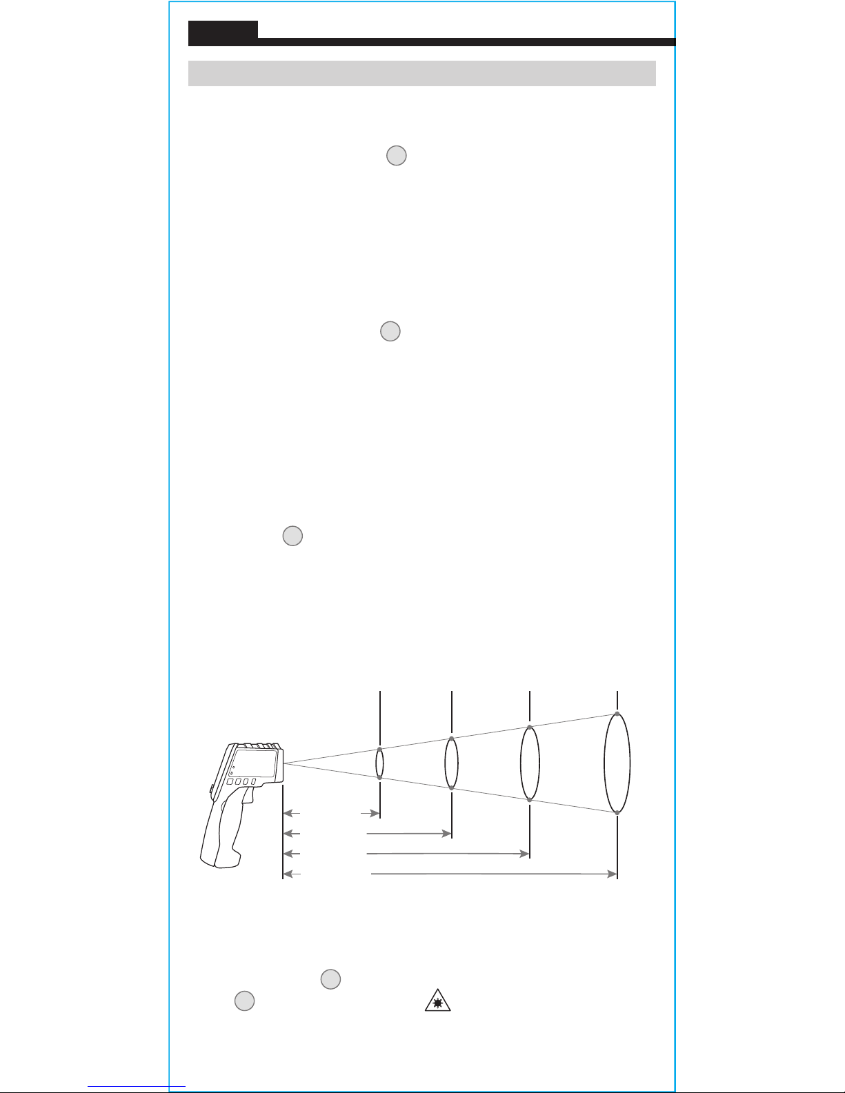
When measuring temperature the meter continuously samples the
object being measured. Following a measurement, repeatedly press
the mode control button
1
to cycle through:
• the maximum temperature value measured ("MAX").
• the average value measured ("AVG").
• the difference between maximum and minimum values
measured ("DIFF").
• the minimum value measured ("MIN").
• press once more to exit the MODE menu.
SETTINGS
User adjustable settings may be defined using the SET control button
2
.
Press SET
2
to enter the settings menu, subsequent presses of SET cycle
through the following list of options:
• emissivity: set the numerical value of the emissivity to match
the surface being measured (see EMISSIVITY section below).
When in this setting the emissivity icon will flash on the display.
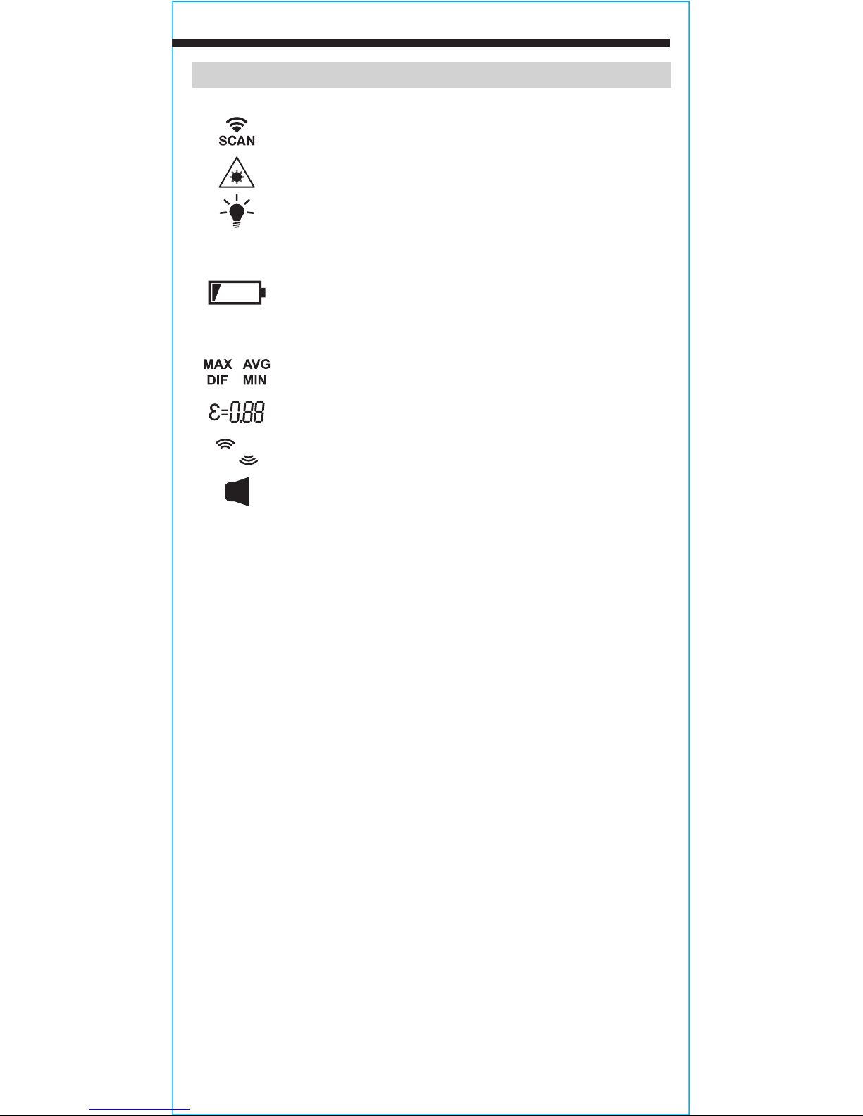
• units: Switch between °F (Fahrenheit) and °C (Celsius). When
in this setting the "°F" or "°C" icon will flash on the display,
indicating the temperature scale that is currently active.
• mute temperature limit alarms: (turn audible limit alarms on/
off). When in this setting the audible icon " "will flash on the
display. When on, the high "
Hi
"/low "
Lo
" icons will be visible and
when off they will not be visible.
• high temperature limit setting: assign a numerical value to the
high temperature limit. When in this setting, the high icon "
Hi
"
will flash on the display.
• low temperature limit setting: assign a numerical value to the
low temperature limit. When in this setting, the low icon "
Lo
"
will flash on the display.
When in any setting, control buttons
1
and
3
function as up/down
to adjust settings and they may be used to select units, turn alarms
on or off, or adjust the numerical values of the respective parameters
up or down.