Kleinwaechter WST 50 User manual

MANUAL
Wrist Strap Tester WST 50
performance test for Electrostatic – Wrist Straps

2 Manual WST 50
Contents
Description ........................................................................................................................................................................... 2
Legende .................................................................................................................................................................................. 3
Spezification ......................................................................................................................................................................... 3
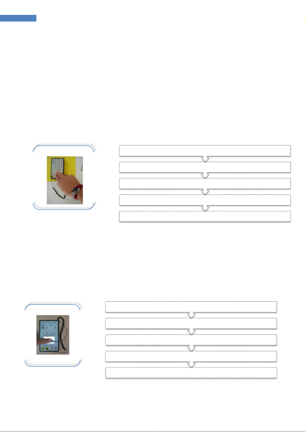
unction ................................................................................................................................................................................. 4
Expiry of wrist strap test........................................................................................................................................... 4
Expiry of cable test ....................................................................................................................................................... 4
Limits .................................................................................................................................................................................. 5
Exchange Batteries ............................................................................................................................................................ 5
Connection ............................................................................................................................................................................ 6
Scope of supply WST 100 SET .................................................................................................................................. 6
Optional accessories ......................................................................................................................................................... 6
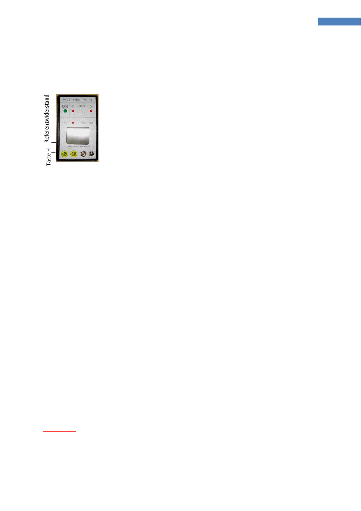
Adjust the limits/calibrate the instrument WST-50 ............................................................................................ 7
Error ........................................................................................................................................................................................ 7
Calibration............................................................................................................................................................................. 8
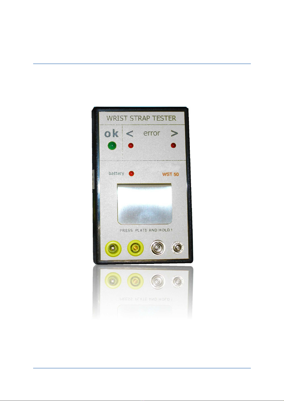
Description
The WST100 serves the function test of electrostatic wrist straps.
The WST-50 is a reliable and advantageous solution for this.
The appliance is portable and because of its battery power employable everywhere.
Specific feature !!
The setting of the limits and the calibration can be done by the customer himself, very simply.
The limits values can be opposed by external resitors.
Doing this with calibrated resitors it is also a calibration of the instrument.
By changing the values you have to do this with resitors of the new limits.
The display includes 4 LEDs a green LED (8mm) for o.k. and 2 red LEDs for error measage plus
1 red LED for low battery.

3 Legende
Legende
1
LED o.k 5
3,5mm handle socket
2
LED Low battery 6
TEST - plate
3
10mm + 4mm Contact 7
2 red LED „Error“
4
ESD-ID/S4 + MC Socket
Spezification
Dimension (L x B x H): 150mm x 88mm x 35mm
Weight: ca. 220 g
Power supp y 4 x Mignon ( AA ) Alkaline Batteries
Alternativ: Plug power supply 7,5V= / 300mA
with 4 x Mignon NiMH Batteries
Disp ay: 1 LED (8mm) green, 3 LEDs (5mm) red,
1 Buzzer
Princip e of Measurement: Current / Voltage Converter
Measuring vo tage: 20V= ±5%
Connection: Power socket and + 3,5mm Socket
Limits: The limits are separate adjustable for the
wrist strap test and the shoe test
Lower Limit: 0....2MOhm
Upper Limit: 5....200Mohm

4 Manual WST 50
Function
The Wrist strap-cables are plugged into the measuring instrument. Then press and hold the Test
-Plate on the appliance with a finger.
When starting the measurement, a short acoustic signal sounds.
It is tested whether the resistance values are within the lower and upper limits.
If the resistance values are between the lower and upper limits, a short acoustic signal sounds
and the green LED lights up.
If the resistance values is outside of the lower or upper limit, no acoustic signal sounds, only the
appropriate red < or > LED lights up.
Expiry of wrist strap test
If the „<“ LED shines the resitor in the cable is defect. Exchange the cable !
If the „>“ LED shines the resitor in the cable ist o high or the wrist strap is defect or dirty. In this
case test the cable separat
Expiry of cable test
If the green LED shines the wrist starp is o.k.
Wait until the result appears
Press and hold the plate with your finger
Connect the wrist strap cable to one of the lower connection sockets
Put on the wrist strap
Shines the > LED again excange the cable
Shines the o.k. LED the cable is ok
Hold it until the result appears
Press the snap faster of the cable on the plate
Disconnect the cable from the wrist strap

5
If the cable is o.k. there is aproblem between the wrist strap and the skin of the arm.
Cause for it may be a very dra skin or to long hairs.
A humidity lotion may solve this problem
If you have always this problem exchange the wrist strap !
Limits
The lower and upper limits are fixed by lower and upper calibrated resistor moduls.
actory default is: wrist strap test lower limit 750kΩ
upper limit 35 MΩ
Other limits are possible without extra charge. The limits can be changed by the customer
anytime see adjustment of the limits.
Eva uation
lower limit Calibrated Value (LCV) LED <
Calibrated Value (LCV) + 10% LED o.k.
upper limit Calibrated Value (UCL) – 10% LED o.k.
Calibrated Value (UCL) + 10% LED >
Exc ange Batteries
The appliance possesses battery supervision. If the battery
voltage is below the limit, the red “low Battery” LED shines.
In this case the batteries must be change.
The battery compartment is on the underside of the appliance.
When installing in new batteries look for the polarity !!
Important ! Use a ka ine batteries on y !

6 Manual WST 50
Connection
The Refernce resitors are in a 3.5mm Plug and will be connected tot he 3.5mm Socket.
Scope of supp y WST 100 SET
•Hand instrument WST 50
•4 x Batteries AA Mignon Alkaline
•Manual
•
Calibration Certification
Optional accessories
WST-50 NT
Power-Set including 4 x NiMH AA Bateries and a Plug power supply
Important ! Before using the power supply replace the alkaline
-batteries with rechargeable NiMH types.
WST-50 RE
Reference – Resitor modul RE-50
Reference – Resitor ypu need one fort he lower and one for the
upper Limit each with Cali ration certification.
The reference- Resitor is mounted in a 3.5mm Plug
The standard values are :
A ower Limit 750kΩ
B upper imit 35MΩ
We can deliver each pair of limits into the limit range without extra charge !
1
Lower limit range 0. . . . 2MΩ ; oberer Grenzwert 5. . . . 200MΩ

7 Adjust the limits/calibrate the instrument WST-50
Adjust t e limits/calibrate t e instrument WST-50
Sequence
•Press and hold button H (hidden), with a small screw driver
•Press the test plate shortly buzzer sounds!
•Release the button H
•Release the test plate
•LED “<” shines
•Connect the resitor modul for the lower limit into the 3.5mm socket
•Press button “H” shortly
•If o.k. the green LED shines and the buzzer appears for 1 second.
•LED “>” shines
•Connect the resitor modul for the upper limit into the 3.5mm socket
•Press button “H” shortly
•If o.k. the green LED shines and the buzzer appears for 1 second.
•The new limit are stored.
By pressingb the plate the instrument will switch off.
Error
If a connected calibration resistor is out of these ranges, all 6 red LEDs flash..
5 x Error Calibration Value
After that the unit switches off.
Important! In this case you must repeat the complete Set – Up !!!
Needed are :
Reference resitors for the ower and
upper imit.
Sma screw driver

8 Manual WST 50
Calibration
Since the values are written directly with the adjustment into the EEPROM, the adjustment of
the limits with calibrated resistors is also simultaneously the calibration of the appliance.
In order to return to the normes, the calibrated resistors can be calibrated by the manufacturer
annually.
With these calibrated resistors, all appliances of the customer can then be calibrated again.
Suggested calibration cycles of the Reference Resitor moduls: annual
©2016 Kleinwächter GmbH
Kleinwächter GmbH
Krummattstraße 9
79688 Hausen
Germany
Tel +49 7622 6863 0
ax +49 7622 6863 40
www.kleinwaechtergmbh.de
Table of contents