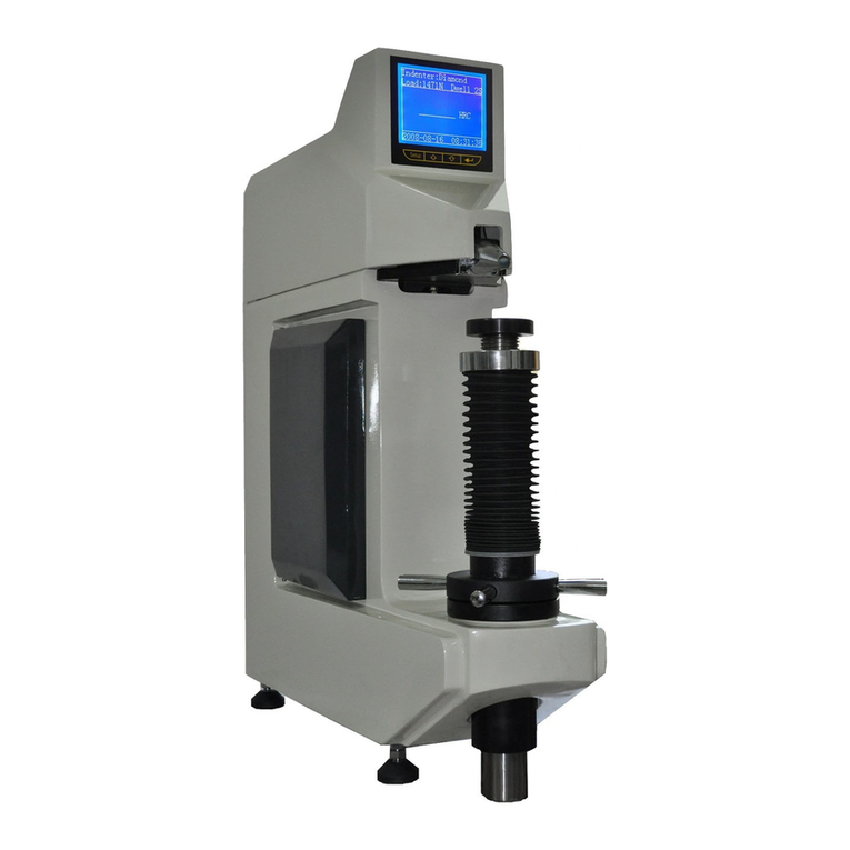
phase II+ 900-365 User manual

900‐365/900‐366
DigitalRockwellHardnessTesters
InstructionManual
21IndustrialAve UpperSaddleRiver,NJ.07458
Tel:(201)962‐7373 Fax:(201)962‐8353
E‐Mail:info@phase2plus.com
WebSite:http://www.phase2plus.com

1
Contents
1 General description…………………………………………………………... 2
2 Key performance parameters………………………………………………. 2
3 Basic configuration and structure…………………………………………. 3
3.1 Standard configuration………………………………………………………. 3
3.2 Structure schematic diagram……………………………………………….. 3
4 Installation and adjustment…………………………………………………. 4
5 Operating methods…………………………………………………………… 4
5.1 Testing preparation…………………………………………………………… 4
5.2 Test parameters setting……………………………………………………… 5
5.2.1 Scale selection………………………………………………………………… 5
5.2.2 Load dwell setting…………………………………………………………….. 6
5.2.3 Auxiliary functions……………………………………………………………. 6
5.2.4 Communication status setting……………………………………………… 9
5.2.5 Buzzer for key…………………………………………………………………. 9
5.2.6 Browse through/print the track record……………………………………. 9
5.2.7 Time setting……………………………………………………………………. 10
5.3 Testing………………………………………………………………………….. 10
5.3.1 The preload loading………………………………………………………….. 10
5.3.2 Automatic testing……………………………………………………………... 10
5.3.3 Unloading………………………………………………………………………. 11
5.4 Shut down………………………………………………………………….…... 11
6 Maintenance and attentions………………………………………………… 11

2
DoNotDiscardShippingCrateasThisMay
beNeededforFutureTransportation.
Use adjustable feet to level the machine. Be sure to lock nuts when completed.

3
The weights must sit flush in the groove of the support saddle
The two pins in the weights should be symmetric.
Don’t turn in any other direction.

4
All weights should unobstructed while taking a test.
The chart above explains which weights get supported when taking a particular Rockwell test.
RockwellBIndentor
1/16” Carbide Ball RockwellCIndentor
Diamond
IncludedIndentors:

5
1Generaldescription
The900‐365&900‐366DigitalRockwellHardnessTesterscanbeuseddirectlytomeasureall
regular Rockwellhardnessscalesanditcanquicklyconvert thathardnessvalueintoHB,HV,
HLD, HK and σbvalue.Loadedwithmanyusefulfeaturessuchasultrapreciseresults, wide
measuringrange,automatictestforcechangeaccordingthescale selection, automatic main
testforceloading/unloading,highresolutiondigitaldisplayandautomaticprinting.The
900‐365/366issuitablefortestinghardnessofcarbonsteel,alloysteel,castiron,nonferrous
metalsandengineeringplastics.
Thetestermeetsthefollowingstandard:ASTME18,ISO6508‐2,andBSENISO6508‐2.
2Keyperformanceparameters
Preload:98.1N(10kgf)
Totaltestforce: 588.4N(60kgf),980.7N(100kgf),1471N(150kgf),
Scales:HRA,HRB,HRC,HRD,HRE,HRF,HRG,HRH,HRK,HRL,HRM,HRP,HRR,HRS,HRV
Loadcycle:3~8s
Loaddwellduration:2~50s
Resolution:0.1HR
Display:HighdefinitionbacklightLCD
Operation:Menuselectable,Membranekeypad
Auxiliaryfunctions:Upper/lowerlimitssetting&alarming,
Datastatistics,Avg.,Max.,Min.,S,R,
Scaleconversion,HV,HB,σb,
CurvedsurfaceAutoCorrection
Dataoutput:Built‐inMiniPrinter
Memory:Max500itemsoftestresultsstoredautomatically
TestingCapacity:900‐365:Vertical:7.87” ThroatDepth:6.50”
TestingCapacity:900‐366:Vertical:16.5” ThroatDepth:7.87”
Dimensions:900‐365:Height: 28.34” Width:7.87” Depth: 21.60”
(550mm×200mm×720mm)
Dimensions900‐366:Height: 39.37” Width:11.02” Depth: 23.60”
(1000mm×280mm×600mm)
Powersupply:singlephase,AC,110V,50~60Hz,4A
Netweight:900‐365:220lbs (100kg) 900‐366:330lbs(150kg)
OptionalCabinet/SupportStand

6
3 Basic configuration and structure
3.1 Standard configuration
BaseMachine 1
Standard hardness block for B scale 1
Standard hardness block for C scale 3
1/16″Carbideball indenter 1
120°cone diamond indenter 1
Mounting screws for indenter 2
Flat anvil 1
“V ”shape anvil 1
Power supply plug 1
Screwdriver 1
Dust cover 1
3.2 Structure schematic diagram
1- screen and keyboard
2- indenter
3- anvil
4- leadscrew and protecting sleeve
5- handwheel
6- weights( in the tester)
7- switch and power panel
8- printer
Figure 3.1
1
6
3
5
2
4
8
7

4
4 Installation and adjustment (900-365 only)
4.1 Remove wood crate top by removing 1each bolt from bottom left and right side of crate and
lifting up crate, then remove the three M10 screws from the underside of the base. Lift the
machine very carefully from the bottom. Remove the tool kit containing the weights and
other accessories.
4.2 The machine should be mounted on a firm bench or table in a clean area, free from vibration
or shock, recommended height is 30”. A hole must be drilled in the top of the work bench to
allow maximum travel of lead screw. Refer to figure 4.1.
4.3 Place the tester on the prepared bench, turn the hand wheel counter-clockwise to lower the
anvil, remove the anti vibration pad; then place a flat anvil in the lead screw and place a
level with the precision of 0.2mm/m on the anvil, adjust the levelling feet of tester to make
the level within +/- 1mm/m, then lock the nuts. Note: This is very important. The
load change will be affected if the machine is not leveled properly
Figure 4.1
4.4 For installation, open the upper cover and back cover of tester, then remove all the packing
materials and suspending weight at the V groove of the lever. Make sure the blade should be
correctly placed in the V groove.
4.5 Reinstall the upper and back cover and connecting the power supply wire.
5 Operating methods
5.1 Testing preparation
Switch on the machine and then the tester will self check. The relative information such as type,
series number, software version will be displayed on screen. Tester will come to main menu after
self-checking; current test parameters will be displayed on screen, and the status at the previous test
will be automatically stored. Figure 5.1.1 is a typical status of Rockwell C testing parameter;
showing the current scale, indenter type should be selected according to the current scale, test force,
load dwell duration, as well as current time.
155
580
Model No. 900-366Model No. 900-365

5
For900‐366Only!

6
Figure 5.1.1
When selecting a particular scale, pay attention to the Indentor that is shown on the display. If the
display shows Diamond as above, then you must install the supplied Diamond Indentor in the
machine. When installing indenter, make sure the surface of the diamond shank is clean. Install
diamond and tighten set screw.
The test force selection is automatically done by the machine once a scale has been chosen.
See details in 5.2.1.
The test can be performed directly according to the procedure 5.3 if all parameters match your
requirements; following procedures should be observed if the modification is necessary.
5.2 Test parameters setting
Press “Setup” key, figure 5.2.1 will be shown on the display, the parameter setting is ready.
5.2.1 Scale selectionPress“”or“ ”key to move cursor to “1” in figure 5.2.1, press “ ”
key and the cursor will begin at“HRC”. Press “”o r“ ”key at this time to scroll through the
optional 15 Rockwell scales HRC、HRA、HRB、HRD、HRE、HRF、HRG、HRH、HRK、HRL、HRM、HRP、
HRR、HRS、HRV will be appear in sequence. When the desired scale appears as figure 5.2.2, press
“”to confirm. At this time test force will be changed automatically according the confirmed
scale.
Press “Setup” key to return to figure 5.1.1;or press “ ”or“ ”key to reset the other parameters.
Figure 5.2.1 Figure 5.2.2

7
5.2.2 Load dwell setting
Load dwell refers to the duration of total test force (i.e. time of primary test force and main test
force). For samples such as steel, cast iron and aluminum, dwell times should be set at 5 seconds
for optimal performance. Changing the dwell time rate will affect the hardness values. An increase
of dwell time will produce lower hardness values caused by creep due to the elasticity of the
material.
Press “Setup” key then Press “”or“ ”key to move cursor to “2” in figure 5.2.1, press
“” key ,then the cursor move to “5S”as figure 5.2.3. Press “”o r“ ”key at this time to
select the dwell time range from 2s~50s,then press “ ”to finish the setting.
Press “Setup” key to return to figure 5.1.1;or press “ ”or“ ”key to reset the other parameters.
Figure5.2.3 Figure5.2.4
5.2.3 Auxiliary functions
The tester has four auxiliary functions, which can be used individually, multi selected or all
selected. Press “Setup” key then Press “”o r“ ”key to move cursor to “3” in figure 5.2.1,
press “ ” key ,then the cursor will move to the position of“ ”and change to“ ” as figure
5.2.4. Press “”or“ ” key at this time to select the desired auxiliary functions, then press
“” to confirm and go into next menu as shown in 5.2.5~5.2.9. There four auxiliary functions
marked as“”, which represent limit setting, data statistics, scale conversion and
curved surface correcting respectively.
5.2.3.1 Limit setting
Press “Setup” key then Press “”o r“ ” key to set the value of upper limit and the value of
lower limit in the figure5.2.5, then press “ ” to confirm.
The upper limit and lower limit will be shown simultaneously with the display of each measuring
result once the function setting has been completed. As figure 5.2.6, the testing result is 59.9HRC,
upper limit is set as 62.0HRC, lower limit is 56.0HRC. If the result is beyond the limitation setting,
a warning on the display and buzzing will occur simultaneously.
?

8
Figure5.2.5 Figure5.2.6
5.2.3.2 Data statistics
The statistics for one group data is available; press “”or“ ”key to determine the value of N (the applicable
scope is 2~99) in figure5.2.7; then press“ ” to confirm.
The values of serial number n and N will be shown simultaneously with the displaying of measuring result each
time after the function setting has been taken into effect. Refer to figure 5.2.6, 5 measurements will be performed
totally, and the current measurement is the 2nd. In case of n=N, that is to say the last measurement had been
completed, the tester will automatically calculate the average
X
, standard deviation S, maximum (Max), minimum
(Min) and the range R as figure 5.2.8 showing after the hand wheel had been unloaded by turning in anti direction.
Of which, the mean value, standard deviation and range can be calculated according to the following equation.
X
=i
X
N
1,
S=2
)(
1
1
i
XX
N
R=Max-Min
Normally, the serial number will plus 1 after each measurement until the n is equal to N (i.e. all of
the N measurements were finished), then begin with statistical calculation. In event one of the
current measurements must be deleted, press “”o r“ ”key in the figure 5.2.6 when the “√”
change to “×”, then unload (i.e. Lowdown the anvil). For this condition, n will not be added by 1,
and the current measurement will not take part in the statistical calculation.
Figure 5.2.7 Figure 5.2.8

9
5.2.3.3 Scale conversion
This function can convert the measured Rockwell hardness value to other scales or strength. Such
as changing the value of HRA scale into HBS, HBW, HV and HK value; changing the value of
HRB scale into HB10, HB30, HV, HLD, σband HK value; changing the value of HRC scale into
HBS, HBW, HV, HLD, σband HK value; changing the value of HRD scale into HV, HK, HB
value; changing the value of HRE scale into HV, HK, HB value; changing the value of HRF scale
into HV, HB value.
For instance, if you intend to convert the HRC value to HV value, press SETUP, then“”or“ ”
key to move the cursor to “3. Function. The press either the UP or DOWN arrow buttons to scroll
through functions until you see “COV”. Then press “ ” to enter the conversion list. Scroll down
to HRC—HV” in figure 5.2.9, and then press “ ” to confirm.
The conversion value will be shown simultaneously with the hardness scale the machine has been
set to take. As figure 5.2.6, the hardness value measured is 59.9HRC, conversion value is 696HV.
Each change is performed within the applicable scope when change is possible; “E” will be shown
on the display if setting is incorrect or not obtainable.
Figure5.2.9 Figure5.2.10
5.2.3.4 Curved surface correcting
The testing results should be corrected if the surface of sample measured is the external surface of cylindrical or
spherical. Press “Setup” key then Press “ ”or“ ” key to select cylindrical surface or spherical surface,
then press “ ” to confirm as figure 5.2.10.
After that, press “ ”or“ ”key to determine curvature radius or the diameter of sphere, and press “ ” to
confirm.
Once this parameter has been set, the measuring result as well as correcting value will be shown on the display. Note:
screen will display respective hardness value (the direct testing result without correction) as well as the corrected
value. As figure 5.2.6, the measuring result is 59.9HRC and the correcting value is “+1.0” HRC.
5.2.3.5 Press “Setup” key to return to figure 5.1.1;or press “ ”or“ ”key to reset the other parameters.

10
5.2.4 Communication status setting
The 900-365 is provided with a digital communication USB port (transmission rate 9600bps), which can be
connected with external computer. After setting, test results of each time will be sent to external computer.
Press “Setup” key then Press“”or“ ” key to move cursor to “4” in figure 5.2.1, press “ ” key then
move the cursor to “Off ”. Press“”or“ ”key at this time, the options “Printer”、“USB”、“Off” will be appear
in sequence. When the desired option appears, press “ ”to complete the selection.
Press “Setup” key to return to figure 5.1.1;or press “ ”or“ ”key to reset the other parameters.
5.2.5 Buzzer for key
Press “Setup” key then Press “ ”or“ ”key to move cursor to “6” in figure 5.2.1, press “ ” key, then the
cursor move to “Off”. Press “ ”or“ ”key to select the “On” or “Off” for the key buzzer, press “ ” key to
confirm finally.
Press “Setup” key to return to figure 5.1.1;or press “ ”or“ ”key to reset the other parameters.
5.2.6 Browse through/print from memory
Press “Setup” key then Press “ ”or“ ” key to move cursor to “7” in figure 5.2.1, then press
“” key. The latest 8 test results will display on the screen as figure 5.2.11. The serial number
and time of the test are displaying simultaneity. There are 500 items of record in maximum. Press
“”or“ ” key to scroll the items. The item of record which the cursor pointed can be printed by
press “ ” key.
Figure5.2.11 Figure5.2.12
Press “Setup” key to return to figure 5.1.1;or press “ ”or“ ”key to reset the other parameters.

11
5.2.7 Time setting
Press “Setup” key then Press “”or“ ” key to move cursor to “8” in figure 5.2.1, press
“” key, figure5.2.12 appears. Press“”or“ ”key to move cursor to “1” in figure 5.2.12, then
press “ ” key, press “”or“ ” to select the year, and press “ ” key to confirm. The
month, also the date, hour, minute and second can be reset in the same way.
Press “Setup” key to return to figure 5.1.1;or press “ ”or“ ”key to reset the other parameters.
5.3 Testing
5.3.1 Preload
Place the sample to be tested on the anvil, and rotate the hand wheel clockwise to raise the anvil
as figure 5.3.1, showing the anvil moving course. Rotate the hand wheel smoothly until the anvil in
figure reaches the end position as figure 5.3.2. the machine will buzz when it reaches its peak. Do
not turn handle any further as an error will occur.
Figure5.3.1 Figure5.3.2

12
5.3.2 Automatic testing
Figure5.3.3 Figure5.3.4
After the preload has been set, the test will be performed automatically as follows: loading main
test force, as figure 5.3.3; holding with dwell time and counting down after loading, refer to figure
5.3.4. Finally, unloading is performed immediately when the dwell time has finished. Test results
will be showed on screen, refer to figure 5.2.6.
5.3.3 Unloading
Once the test has been completed, you should rotate the hand wheel counter-clockwise to lower the
anvil to unload the machine; the screen returns to figure 5.1.1, The machine is now ready to
perform the next test. All parameters are saved and should not need to be modified at this time.
5.4 Shut down
Remove the test force completely, and switch off the power supply. Disconnect power cord if not
being used for an extended period of time.
Warning: Do not test any specimen that cannot be safely and properly positioned
on and supported by the tester anvil.
6 Maintenance and Service
6.1Whenthehardnesstesteristobemovedortransported,theweightsandassemblyMUSTberemovedfromthe
insideofthemachine.Storeinsuppliedtoolkit.
6.2Whenperforminganyadjustments,thepowersupplymustbedisconnected
6.3Paycarefulattentiontoyourindentor.Besuretheshankiscleanandfreeofrust,dirtormetalchipspriorto
installation.
6.4Thesurfaceofanvilandtestblocksshouldbeclean.Nooil,dirt,dust,rustormetalchipsshouldbeonthese
surfacesasitwillcauseerroneousreadings.
6.5Alwayskeepthedustcoveronthemachinewhennotinuse.Neverstoreindamparea.
6.6Theleadscrewoftheanvilshouldbelubricatedperiodically.Applyafewdropsoflightmachineoil,thenrun
theleadscrewupanddownafewtimestodistributetheoil.
6.7Neverdisassembleanyfixedpartsasthiswillautomaticallyvoidanystatedorimpliedwarranties.Ifyouneed
service,pleasecontactPhaseIIdirectlyat(201)962‐7373

13
ApproximateHardnessConversionNumbersforNon‐AusteniticSteels(RockwellCHardnessRange)A
BrinellHardnessNumberC Rockwell SuperficialRockwellNumber
Rockwell
C
150kgf
(HRC)
Vickers
(HV)
10‐mm
Standard
ball
3000kgf
(HBS)
10‐mm
Carbide
ball
3000kgf
(HBW)
Knoop
500‐gf
and
Over
(HK)
A
Scale
60kgf
(HRA)
DScale
100kgf
(HRD)
15‐N
Scale
15‐kgf
(HR15N)
30‐N
Scale
30‐kgf
(HR30N)
45‐N
Scale
45‐kgf
(HR45N)
Scleroscope
HardnessD
68
67
66
65
64
63
62
61
60
59
58
57
56
55
54
53
52
51
50
49
48
47
46
45
44
43
42
41
40
39
38
37
36
35
34
33
32
31
30
29
28
27
26
25
940
900
865
832
800
772
746
720
697
674
653
633
613
595
577
560
544
528
513
498
484
471
458
446
434
423
412
402
392
382
372
363
354
345
336
327
318
310
302
294
286
279
272
266
…
…
…
…
…
…
…
…
…
…
…
…
…
…
…
…
(500)
(487)
(475)
(464)
451
442
432
421
409
400
390
381
371
362
353
344
336
327
319
311
301
294
286
279
271
264
258
253
…
…
…
(739)
(722)
(705)
(688)
(670)
(654)
634
615
595
577
560
543
525
512
496
481
469
455
443
432
421
409
400
390
381
371
362
353
344
336
327
319
311
301
294
286
279
271
264
258
253
920
895
870
846
822
799
776
754
732
710
690
670
650
630
612
594
576
558
542
526
510
495
480
466
452
438
426
414
402
391
380
370
360
351
342
334
326
318
311
304
297
290
284
278
85.6
85.0
84.5
83.9
83.4
82.8
82.3
81.8
81.2
80.7
80.1
79.6
79.0
78.5
78.0
77.4
76.8
76.3
75.9
75.2
74.7
74.1
73.6
73.1
72.5
72.0
71.5
70.9
70.4
69.9
69.4
68.9
68.4
67.9
67.4
66.8
66.3
65.8
65.3
64.8
64.3
63.8
63.3
62.8
76.9
76.1
75.4
74.5
73.8
73.0
72.2
71.5
70.7
69.9
69.2
68.5
67.7
66.9
66.1
65.4
64.6
63.8
63.1
62.1
61.4
60.8
60.0
59.2
58.5
57.7
56.9
56.2
55.4
54.6
53.8
53.1
52.3
51.5
50.8
50.0
49.2
48.4
47.7
47.0
46.1
45.2
44.6
43.8
93.2
92.9
92.5
92.2
91.8
91.4
91.1
90.7
90.2
89.8
89.3
88.9
88.3
87.9
87.4
86.9
86.4
85.9
85.5
85.0
84.5
83.9
83.5
83.0
82.5
82.0
81.5
80.9
80.4
79.9
79.4
78.8
78.3
77.7
77.2
76.6
76.1
75.6
75.0
74.5
73.9
73.3
72.8
72.2
84.4
83.6
82.8
81.9
81.1
80.1
79.3
78.4
77.5
76.6
75.7
74.8
73.9
73.0
72.0
71.2
70.2
69.4
68.5
67.6
66.7
65.8
64.8
64.0
63.1
62.2
61.3
60.4
59.5
58.6
57.7
56.8
55.9
55.0
54.2
53.3
52.1
51.3
50.4
49.5
48.6
47.7
46.8
45.9
75.4
74.2
73.3
72.0
71.0
69.9
68.8
67.7
66.6
65.5
64.3
63.2
62.0
60.9
59.8
58.6
57.4
56.1
55.0
53.8
52.5
51.4
50.3
49.0
47.8
46.7
45.5
44.3
43.1
41.9
40.8
39.6
38.4
37.2
36.1
34.9
33.7
32.5
31.3
30.1
28.9
27.8
26.7
25.5
97.3
95.0
92.7
90.6
88.5
86.5
84.5
82.6
80.8
79.0
77.3
75.6
74.0
72.4
70.9
69.4
67.9
66.5
65.1
63.7
62.4
61.1
59.8
58.5
57.3
56.1
54.9
53.7
52.6
51.5
50.4
49.3
48.2
47.1
46.1
45.1
44.1
43.1
42.2
41.3
40.4
39.5
38.7
37.8

14
ApproximateHardnessConversionNumbersforNon‐AusteniticSteels(RockwellBHardnessRange)A
RockwellSuperficialRockwellNumber
RockwellB
100kgf
(HRB)
Vickers
(HV)
10‐mm
Standard
ball
3000kgf
(HBS)
Knoop
500‐gf
and
Over
(HK)
A
Scale
60kgf
(HRA)
FScale
60kgf
(HRF)
15‐T Scale
15‐kgf
(HR15T)
30‐T Scale
30‐kgf
(HR30T)
45‐TScale
45‐kgf
(HR45T)
100
99
98
97
96
95
94
93
92
91
90
89
88
87
86
85
84
83
82
81
80
79
78
77
76
75
74
73
72
71
70
69
68
67
66
65
64
63
240
234
228
222
216
210
205
200
195
190
185
180
176
172
169
165
162
159
156
153
150
147
144
141
139
137
135
132
130
127
125
123
121
119
117
116
114
112
240
234
228
222
216
210
205
200
195
190
185
180
176
172
169
165
162
159
156
153
150
147
144
141
139
137
135
132
130
127
125
123
121
119
117
116
114
112
251
246
241
236
231
226
221
216
211
206
201
196
192
188
184
180
176
173
170
167
164
161
158
155
152
150
147
145
143
141
139
137
135
131
129
127
125
124
61.5
60.9
60.2
59.5
58.9
58.3
57.6
57.0
56.4
55.8
55.2
54.6
54.0
53.4
52.8
52.3
51.7
51.1
50.6
50.0
49.5
48.9
48.4
47.9
47.3
46.8
46.3
45.8
45.3
44.8
44.3
43.8
43.3
42.8
42.3
41.8
40.9
40.4
…
…
…
…
…
…
…
…
…
…
…
…
…
…
…
…
…
…
…
…
…
…
…
…
…
99.6
99.1
98.5
98.0
97.4
96.8
96.2
95.6
95.1
94.5
93.9
93.4
92.8
93.1
92.8
92.5
92.1
91.8
91.5
91.2
90.8
90.5
90.2
89.9
89.5
89.2
88.9
88.6
88.2
87.9
87.6
87.3
86.9
86.6
86.3
86.0
85.6
85.3
85.0
84.7
84.3
84.0
83.7
83.4
83.0
82.7
82.4
82.1
81.8
81.4
81.1
83.1
82.5
81.8
81.1
80.4
79.8
79.1
78.4
77.8
77.1
76.4
75.8
75.1
74.4
73.8
73.1
72.4
71.8
71.1
70.4
69.7
69.1
68.4
67.7
67.1
66.4
65.7
65.1
64.4
63.7
63.1
62.4
61.7
61.0
60.4
59.7
59.0
58.4
72.9
71.9
70.9
69.9
68.9
67.9
66.9
65.9
64.8
63.8
62.8
61.8
60.8
59.8
58.8
57.8
56.8
55.8
54.8
53.8
52.8
51.8
50.8
49.8
48.8
47.8
46.8
45.8
44.8
43.8
42.8
41.8
40.8
39.8
38.7
37.7
36.7
35.7

15
ApproximateLeeb(TypeD)HardnessConversionforNon‐AusteniticSteels(RockwellCHardnessRange)A
LeebHardness,TypeD
ImpactDevice(HLD)
RockwellCHardness
150kgf(HRC)
VickersHardness
(HV10)
BrinellHardness
10mmSteelBall
3000kgf(HBS)
828
819
809
800
791
782
773
764
755
746
737
729
720
712
703
695
687
679
671
663
655
647
640
632
625
618
611
603
596
590
583
576
570
563
557
551
545
539
533
527
521
516
510
62
61
60
59
58
57
56
55
54
53
52
51
50
49
48
47
46
45
44
43
42
41
40
39
38
37
36
35
34
33
32
31
30
29
28
27
26
25
24
23
22
21
20
762
737
711
688
667
645
625
605
586
568
550
534
517
503
487
473
460
447
434
422
410
398
388
377
368
358
349
339
330
323
314
306
299
291
284
277
271
264
258
251
245
240
234
(721)
(699)
(675)
(654)
634
614
595
577
559
542
526
511
496
482
467
455
442
430
418
407
395
385
375
365
356
347
338
328
320
313
305
297
291
283
276
270
264
258
252
246
240
235
229

16
Weight‐ Load‐ IndentorChart
Scale
Symbol
IndentorTypePreliminary
Force
N(kgf)
Total
Force
N(kgf)
TypicalApplications
A Spheroconical
Diamond
98.07(10)588.4(60)Cementedcarbides,thinsteel,and
shallowcasehardenedsteel
B 1/16”CarbideBall 98.07(10) 980.7(100) Copperalloys,softsteels,aluminum
alloys,malleableiron,etc.
C Spheroconical
Diamond
98.07(10) 1471(150) Steel,hardcastirons,pearlitic
malleableiron,titanium,de epcase
hardenedsteel,otherharderthan
HRB100
D Spheroconical
Diamond
98.07(10)980.7(100)Thinsteelandmediumcase
hardenedsteel,andpearlitic
malleableiron
E 1/8”CarbideBall 98.07(10)980.7(100)CastIron,Aluminumand
magnesiumalloys,andbearing
metals
F 1/16”CarbideBall 98.07(10)588.4(60)
A
nnealedcopperalloysandthinsoft
sheetmetals
G 1/16”CarbideBall 98.07(10)1471(150)Malleableirons,copper‐nickel‐zinc
andcupro‐nickelalloys
H 1/8”CarbideBall 98.07(10)588.4 (60) Aluminum, zinc and lead
K 1/8”CarbideBall 98.07(10)1471 (150)
L ¼”CarbideBall 98.07(10)588.4 (60)
M ¼”CarbideBall 98.07(10)980.7 (100)
P ¼”CarbideBall 98.07(10)1471 (150)
R ½”CarbideBall 98.07(10)588.4 (60)
S ½”Carbideball 98.07(10) 980.7 (100)
V ½”Carbideball 98.07(10) 1471 (150)
15N Spheroconical
Diamond
29.42(3) 147.1 (15)
30N Spheroconical
Diamond
29.42(3)294.2 (30)
45N Spheroconical
Diamond
29.42(3)441.3 (45)
15T 1/16”CarbideBall 29.42(3) 147.1(15)
30T 1/16”CarbideBall 29.42(3)294.2(30)
45T 1/16”CarbideBall 29.42(3)441.3(45)
15W 1/8”CarbideBall 29.42(3)147.1(15)
30W 1/8”CarbideBall 29.42(3)294.2(30)
45W 1/8”CarbideBall 29.42(3)441.3(45)
15X ¼”CarbideBall 29.42(3)147.1(15)
30X ¼”CarbideBall 29.42(3) 294.2(30)
45X ¼”CarbideBall 29.42(3) 441.3(45)
15
Y
½”CarbideBall 29.42(3) 147.1(15)
30Y ½”CarbideBall 29.42(3)294.2(30)
45Y ½”CarbideBall 29.42(3)441.3(45)
BearingMetalsandothervery
softorthinmaterials.Use
smallestballandheaviestlo a d
thatdoe s n’ t
g
iveanvileffect.
SimilartoA,CandDscalesbut
forthinnergagematerial.
SimilartoB,FandGscalesbut
forthinner
g
a
g
ematerial.
VerySoftMaterial
This manual suits for next models
1
Table of contents
Other phase II+ Test Equipment manuals
phase II+
phase II+ SRG-4000 User manual

phase II+
phase II+ 900-345 User manual

phase II+
phase II+ DVM-1000 User manual

phase II+
phase II+ 900-385 User manual

phase II+
phase II+ 900-356 User manual

phase II+
phase II+ PHT-3300 User manual

phase II+
phase II+ PHT-1800 User manual

phase II+
phase II+ PHT-5000 User manual

phase II+
phase II+ SRG-2000 User manual
phase II+
phase II+ SRG 2200 User manual