Metrix MX2040 User manual
MX2040, DYNAMIC SIGNAL CHECKER
Instrucon Manual
Doc# 100911 • REV B (May 2016)
CONTENTS
1 Warnings
2 Scope of Delivery (ordering code KS04)
3 Technical Data
3.1 Handheld Control Unit
3.2 Vibraon Simulator
4 Descripon of Test Procedure
4.1 General
4.2 Vibraon Amplitudes
4.3 Test Setup
4.4 Test Procedure
4.5 Vibraon Indicaon
5 Rechargeable Baery
6 Environmental Informaon
1. Warnings
The instrucon manual is an integral part of the product. Please read the instrucon manual carefully
before using the product, and keep it available for future reference. The measuring system should
only be operated by qualied personnel who have read this instrucon manual. In case of doubt, the
prevailing condions of the area of applicaon and the resulng requirements have to be examined
by an expert before operaon can be commenced.
Correct transportaon, appropriate storage and professional assembly, operaon and maintenance
must be provided in order to ensure proper funconing. Safety instrucons concerning the baery
can be found under secon 5 on page 5 of this manual.
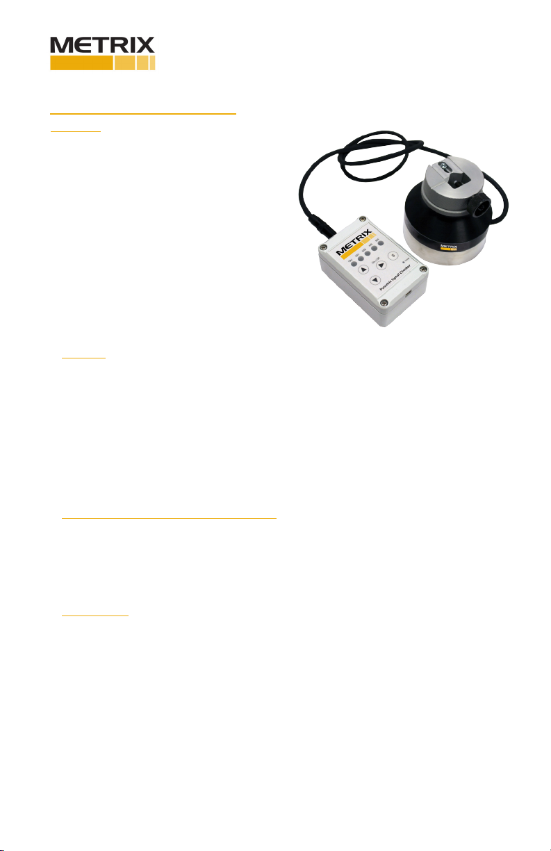
2. Scope of Delivery (ordering code MX2040-001)
• Handheld control unit with baery
• Vibraon simulator
• Baery charger with charging cable
• Instrucon manual
3. Technical Data
3.1 Handheld Control Unit
The device has to be fully charged before the rst operaon. In order to do this, connect the power
adapter to the control unit with the aid of the charging cable. When the device is fully charged, the
charge indicator lamp goes o.
The baery should always be charged when storing the device over longer periods of me. When the
baery is discharged, the simulaon unit can be operated via the provided USB power adapter.
Doc# 100911 • REV B (May 2016) Page 2 of 8
Dimensions: 98 x 64 x 40 mm
Weight: 150 g (5.2 oz) w/o baery
Protecve class: IP 54
Baery: 3.7 volt 1000 mAh LiPoly baery
Charging socket: USB Mini-B
3.2 Vibraon Simulaon
Material: stainless steel / aluminum
Weight: approx 2 kg (4.4 lbs)
Cable: Coaxial cab, PVC coang
Dimensions: 94 mm x Ø 90 mm
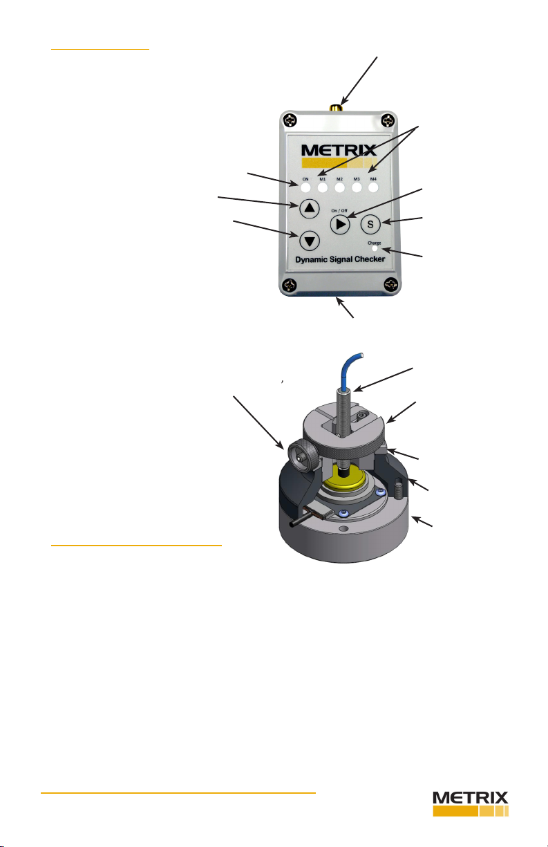
Probe mounng: Prism holder for D = 8 … 22 mm,
M6 locang screw
Probe clamped
in prism holder
GAP adjusng ring
M36 x 1
Lock ring
M36 x 1
Housing
upper part
Housing
lower part
3. Technical Data (cont.)
Stored sengs of
vibraon amplitudes
NEXT
STORE
Charge indicator
USB charging socket
Socket for
connecon to
vibraon simulator
STATUS
UP
DOWN
4. DESCRIPTION OF TEST PROCEDURE
4.1 General
Rotor or sha vibraons are usually measured by means of non-contact eddy-current displacement
probes. You measure the relave moon between rotor and the installed probe. With the Dynamic
Signal Checker the funconality of such systems can be tested on the basis of realisc simulaons of
vibraons.
The Dynamic Signal Checker consists of a compact housing which contains an electrically driven
vibrator. Aer the probe to be tested is clamped in the prism holder, use the GAP adjustment ring
to obtain the necessary voltage (typically 8 to 10 VDC). In combinaon with the compact, baery
driven, handheld control unit the checker can be set into dened oscillaons with 112 Hz and dierent
amplitudes.
With this, the Dynamic Signal Checker enables a funcon test of the enre loop (that is the probe,
driver/transmier funcon, wiring, indicaons and alarms) in one step.
The baery-powered handheld control unit can be aached comfortably by means of the magnet on the
back of the device. The rechargeable baeries enable operaon up to several hours.
Doc# 100911 • REV B (May 2016) Page 3 of 8
4.2 Vibraon Amplitudes
Aer having determined the loop sensivity (probe, cable, driver/transmier) by means of a suitable
stac calibraon unit (e.g. the 9060-001) and a calibrated voltmeter, the Dynamic Signal Checker
vibraon amplitudes can be simulated precisely. The accuracy of the simulaon goes hand-in-hand with
the accuracy of the used voltmeter. With this, the complete system (probe, driver/transmier funcon,
wiring, indicaons, alarms) gets tested.
Basic descripon of the measuring principle:
The Dynamic Signal Checker creates a clean sinusoidal signal with constant frequency (112 Hz) and
variable amplitude, which is picked up by the proximity probe. At the buered-out of the driver/
transmier or monitor this vibraon can be measured as RMS value by means of a common voltmeter
set to “AC”.
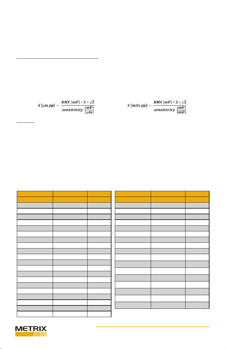
This RMS value can be converted accurately into a peak to peak value, using following formula:
Example:
Reading buered-out: 0.2263 VAC = 226.3 mV AC
Typical sensivity: 7.87 mV/µm (200mV/mil)
Vibraon amplitude [µpp]: 226.3 * 2 * 1.414 / 7.87 = 81.3µm pp,
226.3 * 2 * 1.454/200 = 3.2 mils pp
Simplied formula for the typical measuring loop sensivity of 7.87 mV/µm (200mV/mil):
Spp [µm] = 0.359 * RMS [mV]
Spp [mils] = 0.0141 * RMS [mV]
Conversion Table
Valid for 7.87 mV/µm (200 mV/mil)
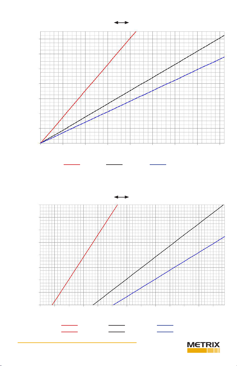
As alternave to this calculang procedure, correspondingly calculated values can be taken from the
following table or diagram
Vibraon Vibraon Vibraon
mV RMS µ - pp mils -pp
0 0 0.0
20 7 0.3
40 14 0.6
60 22 0.8
80 29 1.1
100 36 1.4
120 43 1.7
140 50 2.0
160 57 2.3
180 65 2.5
200 72 2.8
220 79 3.1
240 86 3.4
260 93 3.7
280 101 3.9
300 108 4.2
320 115 4.5
340 122 4.8
360 129 5.1
380 137 5.4
Vibraon Vibraon Vibraon
mV RMS µ - pp mils -pp
400 144 5.6
420 151 5.9
440 158 6.2
460 165 6.5
480 172 6.8
500 180 7.1
520 187 7.3
540 194 7.6
560 201 7.9
580 208 8.2
600 216 8.5
620 223 8.7
640 230 9.0
660 237 9.3
680 244 9.6
700 252 9.9
720 259 10.2
Doc# 100911 • REV B (May 2016) Page 4 of 8
0 50 100 150 200 250 300 350 400
vibraon [mV AC]
4 mV/µ 8 mV/ u10 mV/µ
Conversion “mV AC” “peak to peak [µm or mils]
140
120
100
80
60
40
20
0
vibraon (µm-pp)
5.6
4.8
4.0
3.2
2.4
1.6
0.8
0
vibraon (mils-pp)
Conversion “mV AC” “peak to peak [µm or mils]
vibraon [mV AC]
4 mV/µ 8 mV/u 10 mV/µ
-100mV/mil 200 mV/mil 250 mV/mil
240
220
200
180
160
140
120
100
vibraon (µm-pp)
9.6
8.8
8.0
7.2
6.4
5.6
4.8
4.0
vibraon (mils-pp)
100
150
200
250
300
350
400
450
500
550
600
650
700
26010.4
Doc# 100911 • REV B (May 2016) Page 5 of 8
mils, pp µ-pp mV AC
0.8 20 57
1.6 40 114
- - -
- - -
10.2 260 742
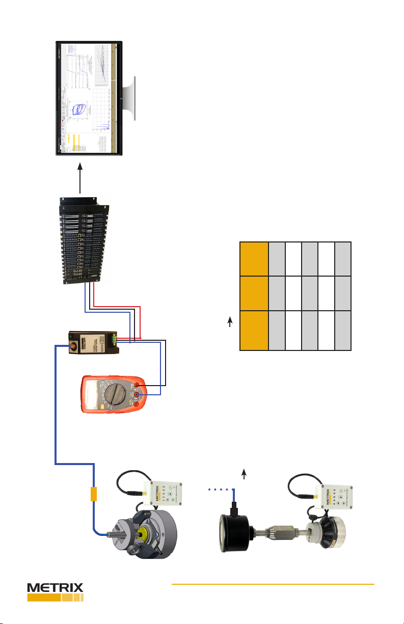
conversion table
mV µm-pp or mils pp
indicaon of measuring values
in the control room
vibraon monitor or
PLC for threshold monitoring
LoopChecker
µm-pp or mils pp
~ mV AC

Doc# 100911 • REV B (May 2016) Page 6 of 8
4.4 Test Procedure
1. Before the dynamic test with the Dynamic Signal Checker the measuring loop sensivity has to be
determined, since deviaons from the specied sensivity inuence the accuracy and indicaon. Using
a stac calibrang unit like the METRIX 9600-001 and a calibrated voltmeter you can verify that probe,
cable and driver match the specicaon
(typically: 7.87 V/mm, 200mV/mil).
2. Place the Dynamic Signal Checker on a solid surface.
3. Screw the GAP adjusng ring + lock ring up to about 1 mm into the upper part of the housing.
4. Connect probe including extension cable with driver/transmier.
5. Connect the voltmeter with the driver/transmier. Set the voltmeter on “DC” in order to read out
the GAP voltage.
6. Carefully insert the probe or the probe holder with reverse-mount probe, into the GAP adjustment
ring and clamp it in the prism holder at a gap signal of about 10 VDC. Avoid contact with the vibrator in
order to not damage vibrator or probe p. Fine adjustment can be achieved by turning of the adjusng
ring; then x it with the lock ring.
The prism holder is suitable for probe diameters of 8 … 22 mm.
7. Connect the simulaon unit to the handheld control unit.
8. Aer pressing the ON/OFF (“ ”) buon once, the device performs a self-test (ashing of all 5 LEDs).
As soon as the “ON” status indicator lights up, the device is ready for operaon.
9. By further pressing of the “ ” buon one by one up to 4 stored default amplitude values (see 11.
for adjustment) can be selected. The amplitude can be read from the voltmeter as RMS voltage signal
[mV] and converted to [µm pp, mils pp] via calculaon formula (p. 4), conversion table (p. 5) or diagram
(p. 6).
10. If the vibraon indicated in the control room doesn’t correspond with the mV signal of the
voltmeter, this may be due to one of the following causes:
• The wiring of the measuring loop is not correct or even broken.
• The vibraon driver/transmier is defecve or calibrated with a wrong measuring range.
• The limit monitoring in the PLC downstream of the transmier is calibrated with
a wrong measuring range.
• The input card of the vibraon monitor is defecve or falsely adjusted, thus a wrong value
is transferred to the monitor.
• The measuring range of the vibraon indicaon is falsely adjusted.
11. In order to adjust individual default values (possible within the range of 0 … 250 µm, 0 to 10 mils)
following steps are necessary:
• Connect a calibrated voltmeter to the buered-out of the exisng driver/transmier or
monitor and set it to “VAC”.
• Read the corresponding mV value of the desired vibraon amplitude from the table (p. 4)
or diagram (p. 5).
• Adjust the vibraon amplitude according to the mV value by means of pushing the buons
“ ” resp. “ ”. You can choose between holding the buons (fast change of values) or
just tapping the buons (slow change of values for rather sensive adjustment).
• The adjusted value is to be compared with the operaon indicaons.
4.4 Test Procedure
• In order to save the individually adjusted value, as shortcut level for future adjustments,
select one of the 4 storage posions (green LEDs) with the buon “ ”. By pressing of
the buon “S” the stored value will be replaced by the new selected value. Note
that, depending on the baery status (14.) and the posion (2.) of the Dynamic
Signal Checker the actual amplitude corresponding to the stored values may slightly dier
over me. The correct seng can be updated anyme.
12. In order to switch the device o manually, the ON/OFF (“ ”) buon has to be pressed for > 2
seconds. If no operaon is performed over a period > 30 minutes, the device switches o automacally.
13. If the “ON” indicator blinks, the device has to be charged. Before damaging exhausve discharge
starts, the device is automacally switched o; 5 seconds ahead all LEDs start blinking.
14. In case of low baery the device can be powered using the USB charging cable.

Doc# 100911 • REV B (May 2016) Page 7 of 8
5. RECHARGEABLE BATTERY
In order to charge the device, connect the charging socket with the provided USB power adapter. As
soon as the baery has reached its full capacity, the charge indicator lamp goes o. The baery should
always be charged when storing the device for longer periods of me.
SAFETY INSTRUCTIONS FOR LITHIUM ION POLYMER BATTERIES (LiPoly baeries)
LiPoly baeries are rechargeable accumulators that feature an extremely high level of energy density.
This type of baery has to be handled with parcular care when in use and when charging/discharging.
Mishandling can lead to a premature wear out or defect, or permanent damage.
Self-Discharge:
LiPoly cells have an extremely low self-discharge rate (approx. 0.2% per day), which is why they can be
stored over longer periods of me without any problems. If the voltage drops below 2.5 volt/cell, it is
imperave that the cell is recharged.
An exhausve discharge is to be avoided, otherwise the cell can suer permanent damage in the form
of capacity loss.
Durability:
The theorecal durability or lifespan of a cell with low levels of discharge currents lies at around approx.
500 charging/discharging cycles. A used baery has to be disposed of correctly!
Baery Disposal:
Never throw used baeries in the regular garbage. In order to help protect the environment, defecve
and used baeries have to be handed in at the appropriate collecon points and in a discharged
condion. Collecon points can be found at the sales outlets for baeries or at municipal collecon
points for hazardous waste. Please mask the bare contacts with adhesive tape in order to avoid short
circuing.
SAFETY INSTRUCTIONS FOR LITHIUM ION POLYMER BATTERIES (LiPoly baeries) (cont.)
DISCLAIMER
Due to the fact that Metrix cannot monitor the handling of the baeries, any liability and warranty is
expressly disclaimed with regard to incorrect charging / discharging or handling.

Doc# 100911 • REV B (May 2016) Page 8 of 8
This electronic equipment was manufactured according to high quality standards to
ensure safe and reliable operaon when used as intended. Due to its nature, this equip-
ment may contain small quanes of substances known to be hazardous to the environ-
ment or to human health if released into the environment. For this reason, Waste Electri-
cal and Electronic Equipment (commonly known as WEEE) should never be disposed of
in the public waste stream. The “Crossed-Out Waste Bin” label axed to this product is
a reminder to dispose of this product in accordance with local WEEE regulaons. If you
have quesons about the disposal process, please contact Metrix Customer Services.
6. ENVIRONMENTAL INFORMATION
info@metrixvibraon.com
www.metrixvibraon.com
8824 Fallbrook Dr. Houston, TX 77064, USA
Tel: 1.281.940.1802 • Fax: 1.713.559.9421
Aer Hours (CST) Technical Assistance: 1.713.452.9703
Table of contents
Other Metrix Test Equipment manuals

Metrix
Metrix MX 535 User manual

Metrix
Metrix MTX 3252e-C User manual

Metrix
Metrix DOX3104 User manual

Metrix
Metrix ScopiX IV Series User manual

Metrix
Metrix TCX01 User manual

Metrix
Metrix MX 67 User manual

Metrix
Metrix HandScope OX5022B User manual

Metrix
Metrix GX-1030 User manual

Metrix
Metrix OX 6062-II User manual

Metrix
Metrix HX0074 User manual

Metrix
Metrix DOX 2 Series User manual

Metrix
Metrix HI-903 User manual

Metrix
Metrix HI 803 Specification sheet

Metrix
Metrix MX 535 User manual

Metrix
Metrix MX 604 User manual

Metrix
Metrix OX 530 User manual

Metrix
Metrix MX 435D User manual

Metrix
Metrix MX 407 User manual

Metrix
Metrix MX 59HD User manual

Metrix
Metrix PX 110 User manual


