Kleton ML994 User manual

Instruction Manual
ML994
Super Heavy-Duty Hydraulic
Hand Pallet Truck
9008-08/29/079257-07/18/16

WARNING!
• Readandunderstandtheentireoperator’smanualbeforeusingthepallettruck.
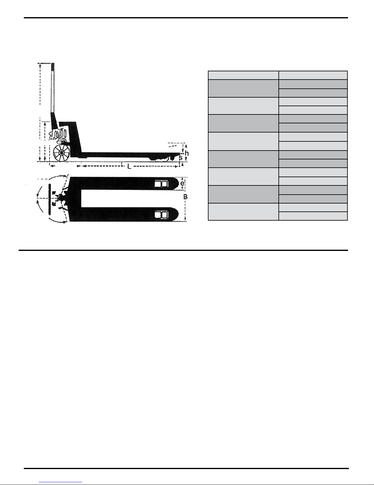
• Don’tloadpallettruckbeyondratedcapacityof11,000lbs.
• Secureloadbeforetransporting.
• Keeptheloadcenteredonthepallet.
• Don’toperateloadedpallettruckonrampsorinclines.
• Alwayswearappropriatesafetyshoes.
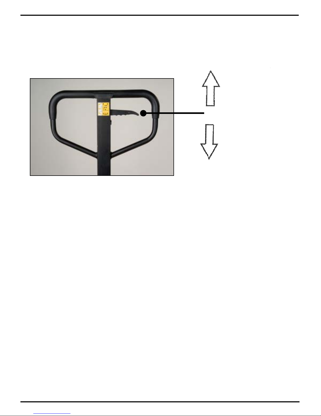
• Neverleavealoadedpallettruckunattendedintheraisedposition;
alwayslowerloadtotheoor.
PALLET TRUCK ASSEMBLY
Note:Individual trucks are assembled and ready to use. Pallet trucks purchased in
crate quantities (6 units to a crate) require some assembly.
Toolsneededforassembly:hammer, flat screwdriver, 14mm wrench, 3/16" pin punch
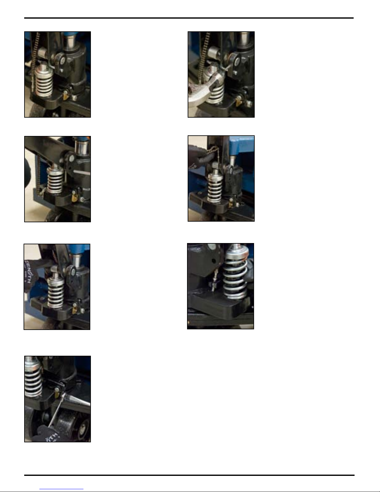
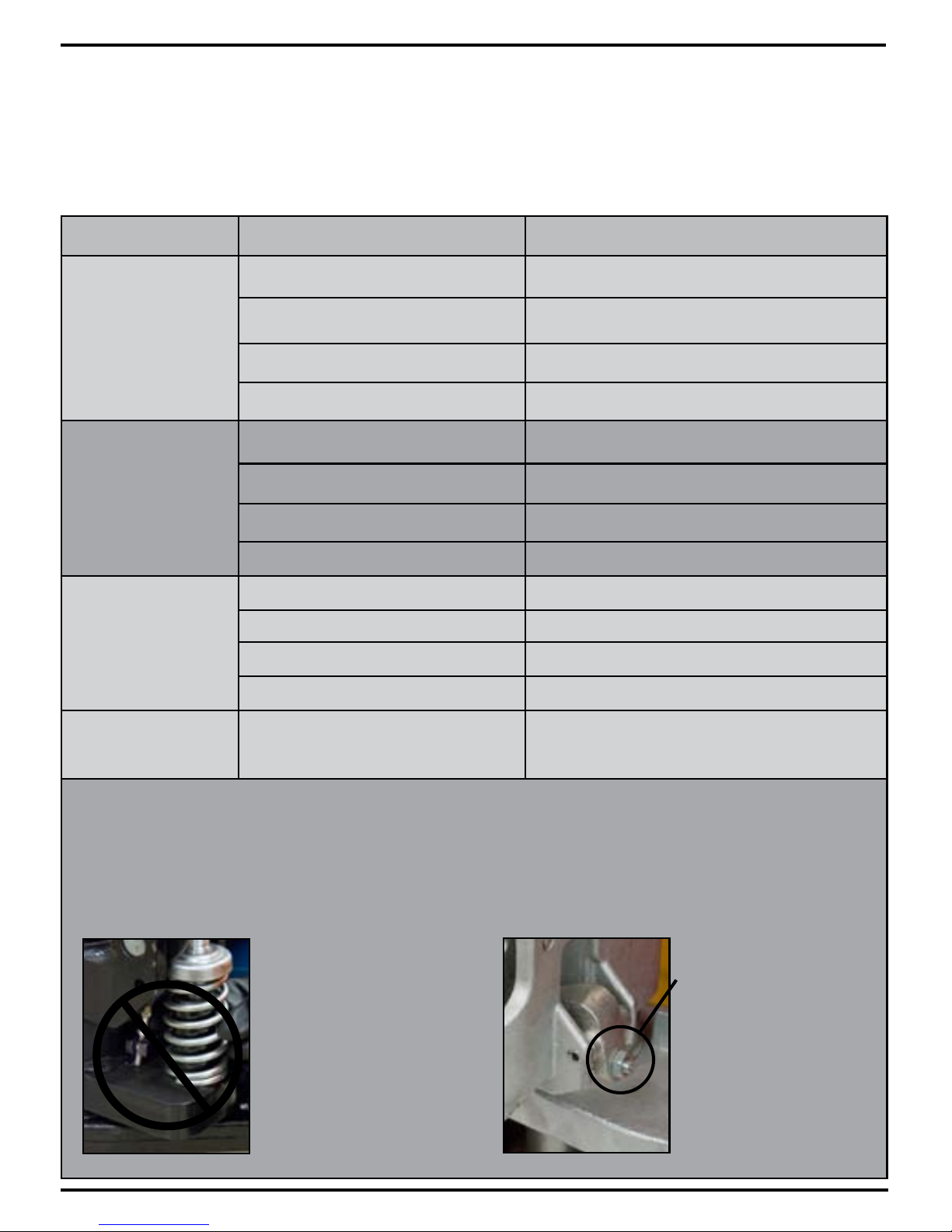
*** IMPORTANT - SAFETY ***
Verify that spring safety pin is in place.
The pin should be well rested in the
holes situated on each side of the pump
housing. If the safety pin is not rested
properly in one of the holes, put pres-
sure on the spring using a “C" clamp
pushing down on the pump stem. Once
pressure is relieved on the pin, reinsert
properly and remove clamp slowly,
To attach handle assembly to the frame:
*** IMPORTANT - CHAIN****
Before this step, make sure to
feed the chain on the outside
of the piston stem roller (see
yellow arrow). If left in its proper
position, it will not be possible to
insert the handle pin and chain,
breakage may occur.
Align handle holes with pump
housing holes and push through
handle pin (see red arrow)
1.
Remove the handle pin as
shown.
3. 4.
Using a hammer and punch,
remove the spring pin.
2.

Make sure that handle pin is
completely through the handle
and resting on the other side.
Drive in the spring pin using a
hammer.
Pull down on the handle to
release the tension on the safety
pin. CAREFULLY remove the
safety pin.
Feed the chain and nut first back
inside the handle THROUGH the
handle pin’s center hole.
***IMPORTANT - TIP ***
Release the up/down lever to
its lowest position to make the
process easier.
Once the chain is in the proper
position, check to see that it
moves freely and that it is not
obstructed.
Feed the end of
the chain into the
cam.
Pump the lever a few times to
raise the forks. Put the up/down
lever to its NEUTRAL position.
Using a 14mm wrench and a
flat screwdriver, adjust the valve
cam so that the forks don’t lower
or rise (if handle is pumped) at
this position.
*** IMPORTANT - FINAL CHECK ***
The handle should be pumped with full strokes to
prime and eliminate air in the system. The up/down
lever should be checked at the handle’s lowest
position as this puts the most tension on the chain.
5. 6.
7. 8.
9. 10.
11. 12.

OPERATING PALLET TRUCK
To raise the forks, place handle lever in UP position (bottom part of the handle slot).
See Figure 2.
Figure 2
To lower forks, pull lever to DOWN position (upper part of the slot).
To freely move the handle, set the lever in NEUTRAL (center notch of the slot).
To lift a load:
1. Lower forks to lowest position.
2. Insert forks under load or into pallet.
3. Place lever in UP position (bottom part of the slot).
4. Move handles up and down until forks reach desired height.
To move a load:
1. Place lever in NEUTRAL position (center notch of the slot).
2. Pull or push to desired location.
To lower a load:
1. Pull lever to the DOWN position (upper part of the slot).
2. Pull forks away from load.
DOWN
NEUTRAL
UP

TECHNICAL PARAMETERS
MAINTENANCE
Model No. ML994
Capacity 11000 lbs.
5000 kg
H - Maximum Raised Height 7 3/8"
187 mm
S - Lowered Height
3"
75 mm
L - Fork Length
48"
1220 mm
E - Fork Width 6 1/4"
160 mm
B - Fork Outside Distance
27"
685 mm
Diameter of the steer wheel 7" x 2"
180 mm x 50 mm
Dimensions of the load wheel 3" x 3"
76 mm x 76 mm
99
99
1226
394 mm
445 mm
1245 mm
Lubrication
Your KLETON pallet truck is equipped with grease fittings in order to facilitate greasing its bearings.
It is recommended to apply grease every 6 months.
AddingOil(ifrequired)
1. Lower the pallet truck forks to their lowest point using the up/down lever on the handle. You will notice that
the piston is now completely inside the pump assembly.
2. Remove the oil reservoir plug (part #328).
3. Using an oil can, add the hydraulic oil. The oil level should be up to the bottom of the hydraulic oil
reservoir’s fill hole.
4. Re-insert the oil reservoir plug (part #328).
5. Pull the lever on the handle upwards to put it in the DOWN position (see page 3 for details).
Then, pump the handle up and down a minimum of 10 times in order to remove any air bubbles in the system.
Note: Unless the pump is leaking, you should not have to add any additional oil.
Please contact your KLETON distributor if your pallet truck is leaking.

TROUBLESHOOTING
Possible problems could arise in the operation of your hydraulic pallet truck. Their probable cause(s) and
corrective action(s) follow:
Condition Probable Causes Corrective Action
Hydraulic unit does
not lift
Oil low in tank Make sure there is no till leakage from valve and add oil.
Relief valve not seated properly or air in the
system See “Cleaning Relief Valve" in this manual.
Defective pressure seal in main cylinder Consult authorized service centre.
Relief valve not adjusted properly Adjust valve by pressure adjustment screw
Once lifted truck
lowers by itself
Relief valve not seated properly See “Cleaning Relief Valve" in this manual.
Defective pressure seal in main cylinder Consult authorized service centre
Relief valve not adjusted properly Adjust valve by pressure adjustment screw
Oil leakage Consult authorized service centre
Fork does not lower
Cam chain broken Replace cam chain.
UP-DOWN cam nut out of adjustment Refer to “Adjusting UP-DOWN Cam" in this manual.
Broken fork rods and linkage Consult authorized service centre
Cam chain lock-nut fallen off Replace cam chain lock-nut
Lever does not set at
NEUTRAL position Relief valve not adjusted properly Adjust valve by pressure adjustment screw
Cleaning Relief Valve
Over time, relief valve may become clogged with debris and will not work properly.
To clean relief valve, flush the hydraulic system as follows:
Hold the UP/DOWN lever to the DOWN position and move the handles up and down several times.
Adjusting UP-DOWN Cam
DO NOT adjust the up/down
lever control using the lock
nut at the end of the handle
chain. If nylon locking threads
are removed from the screw
threads, rolling vibration will
cause the nut to unscrew and
fall off, leaving the up/down
lever unusable.
Use proper set screw
and lock nut adjustment
located on the side of the
pump. This feature was
designed to ease the pallet
truck adjustment.
Tools required are:
flat screwdriver and a
14mm wrench.

Hydraulic Hand Pallet truck assembly and Parts lists
Handle Assembly
A
General Assembly
No. Order No. Description Qty No. Order No. Description Qty
201 BODY WELDMENT 1 101 MN369 PULLING ROD 1
202 ADJUSTMENT SCREW 1 102 CHAIN 04B-1-121 1
203 CONNECTING FORK EAR 2 103 DROP BOLT M5X30 1
204 CIRCLIP FOR SHAFT 2 104 HEXAGONAL NUT M5 1
205 CONNECTING SHAFT 2 105 LOCK NUT M5 1
206 CIRCLIP FOR HOLE 2 106 ELASTIC CYLINDRICAL PIN 5x35 1
207
CONNECTING SHAFT FOR BACKING PLATE
2 107 HANDLE LOCATING SHAFT 1
208 LEVER BRACKET 1 108 SPACER BUSH 2023165 2
209 LEVER BRACKET SHAFT 1 109 ELASTIC CYLINDRICAL PIN 4X20 1
210 ADJUSTING NUT 2 110 ROLLER SHAFT 1
211 PUSH ROD (1220/1150MM) 2 111 ROLLER 1
212 FLAT WASHER 4 112 ROLLER BUSH 1
213 PUSH ROD CONNECTING SHAFT 2 113 HANDLE WELDMENT 1
214 SPLIT PIN 4 114 ELASTIC CYLINDRICAL PIN 6X30 1
215 LOAD WHEEL FRAME 2 115 LOCATING SPRING STRIP 1
216
LOCATING SHAFT OF LOAD WHEEL FRAME
2 116 HANDLE SPRING 1
217 ELASTIC CYLINDRICAL PIN 2 117 ELASTIC CYLINDRICAL PIN 4X30 1
218 ELASTIC CYLINDRICAL PIN 8 118 ELASTIC CYLINDRICAL PIN 4x10 1
219 SIDE PLATE(DOUBLE WHEEL) 4 119 CONTROL HANDLE 1
220 FLAT WASHER 8 120 ROLLER HANDLE 1
221 LOAD WHEEL SHAFT 4 121 ELASTIC CYLINDRICAL PIN 4X16 1
222 BEARING 8 A MN525 HANDLE ASSEMBLY
223 MN240 LOAD WHEEL 4
General Assembly

PumP assembly and Parts lists
C
General Assembly:
B
No. Order No. Description Qty No. Order No. Description Qty
301 SPRING GLAND 1 326 SEALING RING 1
302 PUMP PLUNGER 1 327 PUMP WELDMENT 1
303 SPRING 1 328 OIL FIL PLUG 1
304 ANTI-DUST RING 1 329 BONDED SEAL 1
305 SEALING RING 1 330 O RING 1
306 GAG LEVER POST 1 331 COPPER NUT 1
307 MN527 HALF RING 2 332 O RING 1
308 MN528 BEARING 6205 4 333 O RING 1
309 MN523 STEER WHEEL 2 334 ROD 1
310 ELASTIC PIN 8*50 1 335 SPRING 1
311 ELASTIC PIN 5*30 2 336 STEEL BALL 1
312 RETAINING PLATE 1 337 HIGH PRESSURE VALVE CORE 1
313 CIRCLIP FOR SHAFT 55 1 338 CONNECTING SHAFT 1
314 BEARING 51111 1 339 NOTCHED RING 1
315 WASHER 1 340 O-RING 1
316 STEER WHEEL SHAFT 1 341 HIGH PRESSURE VALVE BODY 1
317 HOLDING SCREW 1 342 NOTCHED RING 1
318 HEX NUT 1 343 O-RING 1
319 SHAFT PIN 1 344 ELASTIC CYLINDRICAL PIN 1
320 SPLIT PIN 1 345 LEAF SPRING 1
321 FOOT CONTROL ARM 1 346 CROSS RECESS HEAD SCREW 1
322 PISTON ROD 1 347 HIGH PRESSURE VALVE CORE SPRING 1
323 STEEL BALL 1 348 SPRING GLAND 1
324 DUST RING 1 B MN524 PUMP ASSEMBLY 1
325 O RING 1 C MN652 CONTROL VALVE ASSEMBLY 1
Table of contents
Other Kleton Truck manuals
Popular Truck manuals by other brands

freightliner
freightliner PX113064S T 2016 manual

SANY
SANY SRT45 Safety, operation and maintenance manual

Powertow
Powertow 65 EZ VIPER owner's manual

URAL Motorcycles
URAL Motorcycles 4320M Operation manual

chevrolet truck
chevrolet truck Light Duty Truck 1994 Series Repair manual

U-Line
U-Line H-3405 operating instructions