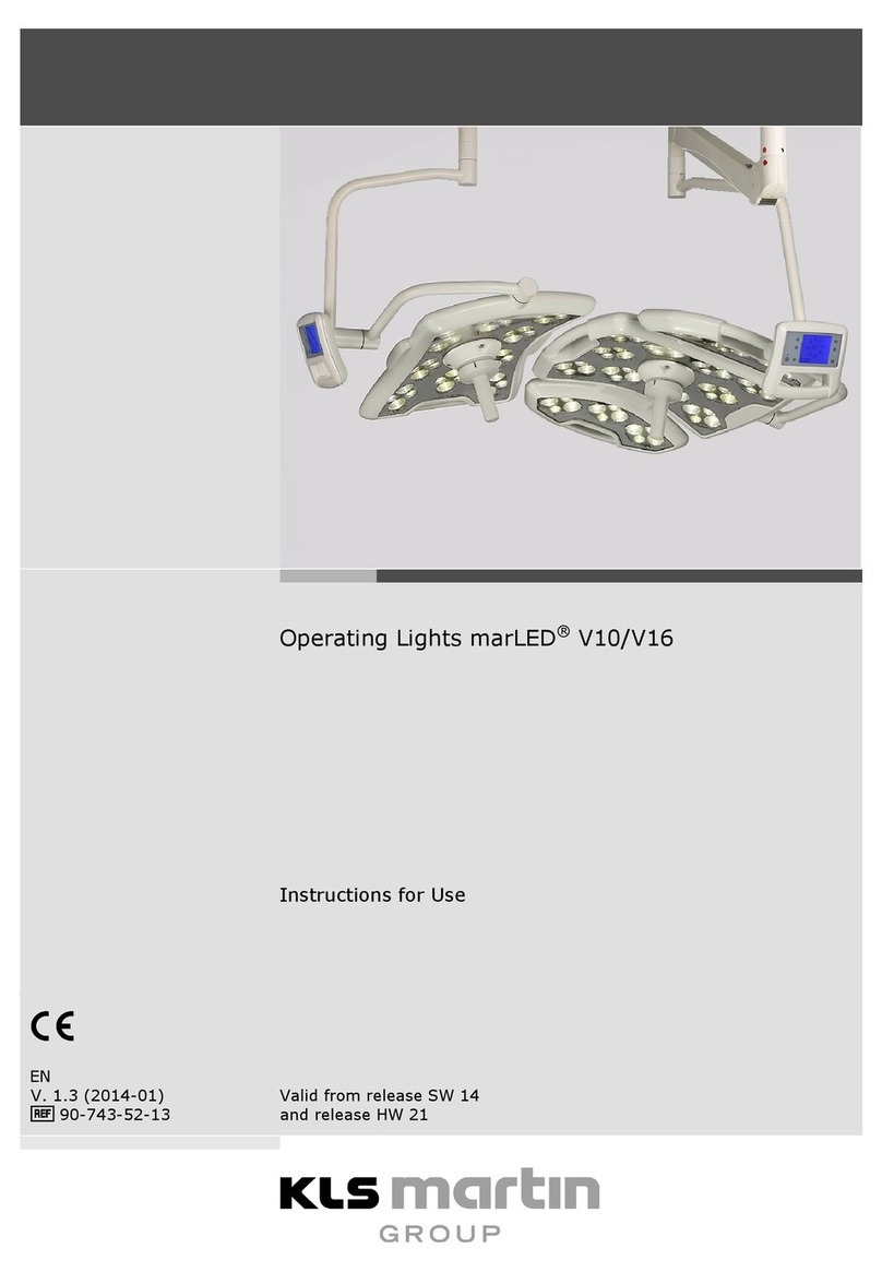
KLS Martin group marLED E3 User manual

Front Cover
English
Operating Lights marLED
® E3, E9, E9i, E15, battery and
marLED®
E3 on ceiling tube Ø 110 mm
Service Manual
90-610-62-11
Revision 2
Date of Release: 2018-07
Valid from hardware release HW
00 and software release SW 00

2Revision 2
Symbol Explanation
Safety alert symbol
CAUTION Indicates a situation which, if not avoided, could result in minor or
moderate injury.
WARNING Indicates a situation which, if not avoided, could result in death or
serious injury.
DANGER Indicates a situation which, if not avoided, will result in death or
serious injury.
Consult Instructions for Use
Follow Instructions for Use
Catalogue number
Serial number
Keep dry
Information on minimum and maximum temperature for storage and
transportation.
See section 17 “Technical Data”, page 183 for valid values.
Information on minimum and maximum atmospheric pressure for storage and
transportation.
See section 17 “Technical Data”, page 183 for valid values.
Information on minimum and maximum atmospheric humidity for storage and
transportation.
See section 17 “Technical Data”, page 183 for valid values.
Fragile, avoid pressure and shock
Stacking height max. 2 layers, max. load 250 kg per item

Revision 2 3
Hazard Class 9 material (label on package)
Manufacturer
CE marking of conformity
NRTL certification mark from TÜV Rheinland
Warning: Dangerous high voltage!
Apply screw lock to the screw, see section 4.3 “Screw Lock”, page 18.
Tighten screw/nut with specified torque, see section 4.4 “Screw Torques”, page 19.
Grease at this location, see section 4.5 “Greasing”, page 19.
This product may not be disposed of as normal household garbage, see
section 16.2 “Disposal of the Device”, page 182..

Service Manual
Operating Lights marLED® E3, E9, E9i, E15, battery and
marLED® E3 on ceiling tube Ø 110 mm
4Revision 2
Contents
1Notices Concerning this Document..........................................................................9
1.1 Safety...................................................................................................................................9
1.2 Notices for Service Technicians .......................................................................................... 9
1.3 Terms & Acronyms.............................................................................................................. 9
1.4 Validity of this Document..................................................................................................10
1.5 Other Applicable Documents............................................................................................ 10
1.6 Symbols Used in this Document ....................................................................................... 10
1.7 Cable Colors ...................................................................................................................... 11
2Product Liability and Warranty...............................................................................11
2.1 General Information ......................................................................................................... 11
2.2 Hotline............................................................................................................................... 12
2.3 User’s Inspection...............................................................................................................12
2.4 Warranty ........................................................................................................................... 12
3Intended Use ..........................................................................................................13
3.1 Intended Purpose.............................................................................................................. 13
4Safety Notices .........................................................................................................15
4.1 General Information ......................................................................................................... 15
4.2 Personal Protection........................................................................................................... 16
4.3 Screw Lock......................................................................................................................... 18
4.4 Screw Torques................................................................................................................... 19
4.5 Greasing ............................................................................................................................ 19
5Power Supply ..........................................................................................................20
5.1 Power Modules of Lights/Ceiling Tube Structure.............................................................20
5.2 Current SMPS Modules from HW 18 ................................................................................ 21
5.2.1 Available Power Module Versions .................................................................................................21
5.2.2 Circuit Diagram without ASPS Assembly........................................................................................22
5.2.3 Circuit Diagram with integrated ASPS Assembly ...........................................................................23
5.2.4 Integrated ASPS Changeover Function (Optional).........................................................................24
5.2.5 Adjusting the Voltage.....................................................................................................................24
5.3 Power Supply marLED® E3 on Ceiling Tube Ø 110 mm .................................................... 25
6CAN Bus System/RS232 ..........................................................................................27
6.1 CAT Wiring from HW 30.................................................................................................... 27
6.1.1 Cable Specifications .......................................................................................................................29
6.1.2 Pin assignment according to TIA-568 B..........................................................................................29
6.1.3 Circuit Diagram, Video Cabling, CAN Bus Wiring ...........................................................................30
6.1.4 Light System with CAN Bus and 1 Ceiling Tube, no Galvanic Isolation ..........................................31
6.1.5 Standard CAN Board, no Galvanic Isolation...................................................................................32

Service Manual
Operating Lights marLED® E3, E9, E9i, E15, battery and
marLED® E3 on ceiling tube Ø 110 mm
Revision 2 5
6.1.6 Terminating Resistor S1 without Coupler......................................................................................32
6.1.7 Pin Assignment of Cable Connection Terminal Block X3 ...............................................................33
6.1.8 CAN Board with Galvanic Isolation ................................................................................................34
6.1.9 Terminating Resistor S1 with Coupler............................................................................................34
6.1.10 Light System with CAN Bus and 1 Ceiling Tube, with Galvanic Isolation .......................................36
6.1.11 Connecting the Bus Couplers to the CAN Board............................................................................37
6.1.12 Connecting the Bus Couplers to the Power Supply .......................................................................37
6.1.13 Bus Coupler Connection Board Pin Assignment ............................................................................38
6.1.14 Troubleshooting on Bus Coupler ...................................................................................................39
6.1.15 Coupler Block Diagram...................................................................................................................40
6.1.16 Wall Box Connections (Rear)..........................................................................................................40
6.1.17 Connecting the Wall Box to the Predecessor Wall Cable ..............................................................41
6.1.18 marTouch® Wall Box Connections (Front).....................................................................................41
6.1.19 marTouch® Wall Box Pin Assignment ............................................................................................42
6.2 COM Interface (RS232) ..................................................................................................... 43
6.2.1 Connecting the COM Interfaces.....................................................................................................43
6.2.2 COM Interfaces marLED® and surgiCam on Ceiling Tube from HW 37 .........................................44
6.2.3 COM Interfaces for Separate Installation HW 30 – HW 36............................................................45
6.2.4 COM Interfaces for Separate Installation up to HW 09 .................................................................46
6.2.5 Pin Assignment X2 (CAN, RS232) ...................................................................................................47
6.3 CAN Bus Cabling up to HW 09........................................................................................... 47
6.3.1 Overview of Camera System surgiCam HD, Cable and Connection Options .................................48
6.4 Addressing......................................................................................................................... 49
6.4.1 DIP Switches for CAN Addresses and Terminating Resistors.........................................................49
6.4.2 DIP Switches SW6 for CAN Addresses and Configuration..............................................................49
6.4.3 DIP switch SW1 marLED® for Terminating Resistor.......................................................................50
6.4.4 DIP switch SW1 surgiCam ..............................................................................................................51
6.4.5 CAN Address Setting from HW 30..................................................................................................51
6.4.6 Setting of the CAN Addresses up to HW 09 ...................................................................................52
7Central Bearing Shaft/Tracking Arm/Spring Arm Wiring .......................................53
7.1 Central Bearing Shaft (Slip Rings)......................................................................................53
7.1.1 Replacing the Contact Block ..........................................................................................................53
7.1.2 Checking the Voltage on Tracking Arm..........................................................................................54
7.2 Tracking Arm/Spring Arm from HW 30.............................................................................57
7.2.1 Tracking arm/ceiling tube ..............................................................................................................57
7.2.2 Circuit Diagram for 3-Pole Tracking Arm marLED® E9, E9i, E15 (battery) .....................................58
7.2.3 Circuit Diagram for 3-Pole Tracking Arm marLED® E3 ...................................................................58
7.2.4 Circuit Diagram for 5-Pole Tracking Arm with Wall Control Panel ................................................58
7.2.5 Circuit Diagram for 9-Pole Tracking Arm with Wall Control Panel and surgiCam HD/SD..............59
7.3 Tracking Arm/Spring Arm up to HW 09 ............................................................................ 62
7.3.1 Circuit Diagram for 5-Pole Tracking Arm with Wall Control Panel ................................................62

Service Manual
Operating Lights marLED® E3, E9, E9i, E15, battery and
marLED® E3 on ceiling tube Ø 110 mm
6Revision 2
8Video Cabling..........................................................................................................63
8.1 CAT from HW 30................................................................................................................ 63
8.1.1 Video Cabling to Monitor...............................................................................................................64
8.1.2 Video Cabling to Wall Box..............................................................................................................65
8.1.3 Cabling of the Wall Box surgiCam..................................................................................................66
8.1.4 Cabling of the NDS ScaleOR with the Wall Boxes ..........................................................................67
8.1.5 Video Cabling to Monitor and then to Wall Box............................................................................68
9Working on Light Head ...........................................................................................70
9.1 Dismounting the Light Head .............................................................................................70
9.1.1 Adjusting the Height Stop on AC2000............................................................................................71
9.1.2 Removing the Light Head from the Spring Arm .............................................................................72
9.1.3 Reinstalling the Light Head on the Spring Arm ..............................................................................73
9.2 Light Head Overview......................................................................................................... 74
9.3 Service Plug ....................................................................................................................... 75
9.4 Preparatory Work on Light Head ......................................................................................76
9.5 Disconnecting the Battery Cable (marLED® E battery)..................................................... 77
9.6 Connecting the Battery Cable (marLED® E battery) ......................................................... 77
9.7 Removing the Light Engine ...............................................................................................78
9.8 Opening the Light Housing................................................................................................ 79
9.9 Replacing the Gasket......................................................................................................... 81
9.10 Replacing the Battery Packs.............................................................................................. 81
9.11 Replacing the Control Panel Foil ....................................................................................... 84
9.12 Mounting and Connecting the surgiCam Daughterboard ................................................ 86
9.13 Replacing the Control Electronics..................................................................................... 87
9.13.1 Connectors for Light Engines .........................................................................................................88
9.13.2 Connection terminal for Supply Voltage/CAN Bus ........................................................................89
9.13.3 Connection for D-Sub Plug of sensoGrip........................................................................................90
9.14 Replacing the Cardanic suspension...................................................................................91
9.15 Closing the Light Housing..................................................................................................94
9.16 Installing the Light Engines ...............................................................................................96
9.16.1 Light Engine Variants......................................................................................................................96
9.16.2 Installing the Light Engines ............................................................................................................98
10 Wall Control Panel..................................................................................................99
10.1 Connecting a Wall Control Panel from HW 37..................................................................99
10.2 Connecting a Wall Control Panel HW 30 – HW 36.......................................................... 100
10.3 Connecting a Wall Control Panel up to HW 35...............................................................101
10.4 Parameter Menu for Switching between Modbus and Serial Control ...........................102
10.4.1 Adjusting Parameter 0001 ...........................................................................................................102
10.4.2 Activating and Verifying the Adjusted Parameter .......................................................................103
10.5 Wall Control Panel Error Messages ................................................................................ 104
10.6 Wall Control Panel and surgiCam Wiring up to HW 09 ..................................................106

Service Manual
Operating Lights marLED® E3, E9, E9i, E15, battery and
marLED® E3 on ceiling tube Ø 110 mm
Revision 2 7
11 Description of Assemblies ....................................................................................107
11.1 Control Electronics Board ...............................................................................................107
11.1.1 Design including Miniature Fuses from HW 40............................................................................108
11.1.2 Design including Miniature Fuses HW 32 – HW 39......................................................................109
11.1.3 Design including Miniature Fuses up to HW 31...........................................................................110
11.2 Light Engines ...................................................................................................................111
11.2.1 Light Engine Pin Assignment from HW 40 ...................................................................................111
11.2.2 Light Engine Circuit Diagram from HW 40 ...................................................................................111
11.2.3 Light Engine Pin Assignment up to HW 39...................................................................................112
11.2.4 Light Engine Circuit Diagram up to HW 39...................................................................................112
11.2.5 Cable Harness from Control Electronics Board to Light Engine of marLED® E9(i).......................113
11.2.6 Cable Harness from Control Electronics Board to Light Engine of marLED® E15 ........................113
11.3 Control Panel Foil............................................................................................................114
11.3.1 Description of the Control Panel Foil from HW 32 ......................................................................114
11.3.2 Additional Function marLED® E battery.......................................................................................116
11.3.3 Description of the Control Panel Foil up to HW 31......................................................................118
11.3.4 Circuit Diagram of the Control Panel Foil from HW 32................................................................118
11.3.4.1 Control Panel Foil Circuit Diagram for marLED® E battery 120
11.3.5 Control Panel Foil Circuit Diagram up to HW 31..........................................................................122
12 Programming ........................................................................................................123
12.1 marLED® E Interface Adapter..........................................................................................123
12.1.1 Scope of Delivery .........................................................................................................................123
12.2 USB Serial Adapter ..........................................................................................................124
12.3 Software Update.............................................................................................................125
12.3.1 Installing the C2Prog Programming Software on Your PC ...........................................................125
12.3.2 Connecting the Interface Adapter ...............................................................................................126
12.3.3 Programming Master ...................................................................................................................128
12.3.4 Programming Slave ......................................................................................................................129
12.3.5 Programming the Camera Daughterboard ..................................................................................131
12.3.6 Configuring the Light....................................................................................................................132
13 Maintenance.........................................................................................................133
13.1 Troubleshooting..............................................................................................................133
13.1.1 Error Messages, Parameters........................................................................................................133
13.1.2 Error Patterns, Possible Causes and Corrective Actions ..............................................................133
13.2 Identifying Master and Slave Channel ............................................................................134
13.3 Inspection and Maintenance ..........................................................................................135
13.3.1 Notices Concerning the Inspection..............................................................................................135
13.3.2 Notices Concerning the Inspection Plan ......................................................................................136
Inspection plan .....................................................................................................................137
13.3.3 Test Instructions...........................................................................................................................141

Service Manual
Operating Lights marLED® E3, E9, E9i, E15, battery and
marLED® E3 on ceiling tube Ø 110 mm
8Revision 2
13.4 Rating Plate and Serial Number...................................................................................... 164
13.4.1 Serial Number Structure ..............................................................................................................165
13.4.2 surgiCam Serial Number ..............................................................................................................170
13.5 Spare Parts ...................................................................................................................... 171
14 Change History......................................................................................................171
14.1 Overview of Software Changes.......................................................................................171
14.2 Overview of Hardware Changes .....................................................................................177
15 Transport ..............................................................................................................182
15.1 Transport Regulations..................................................................................................... 182
16 Disposal.................................................................................................................182
16.1 Packaging ........................................................................................................................182
16.2 Disposal of the Device..................................................................................................... 182
16.3 National Regulations.......................................................................................................182
17 Technical Data ......................................................................................................183
17.1 Technical Data for marLED® E9/E9i ................................................................................ 183
17.2 Technical Data for marLED® E9/E9i battery....................................................................185
17.3 Technical Data for marLED® E15..................................................................................... 187
17.4 Technical Data for marLED® E15 battery........................................................................189
17.5 Technical Data for marLED® E3....................................................................................... 191

Service Manual
Operating Lights marLED® E3, E9, E9i, E15, battery and
marLED® E3 on ceiling tube Ø 110 mm
Revision 2 9
1Notices Concerning this Document
1.1 Safety
Failure to observe this document can lead to serious or even lethal
injury to the patient or the user!
•
Please observe all instructions, in particular cautionary notes, warnings and danger information!
1.2 Notices for Service Technicians
•To keep the lights as well as their mounting/suspension systems in a perfect technical condition, it is
essential for you as a service technician to perform your work with utmost precision and expertise. This
service document is intended to support you in performing your highly responsible work.
•While participation in a service training course authorizes technicians to perform mounting and service
work, it does not confer any authorization for providing user advice! Regarding the latter,
Gebrüder Martin offers special product training.
•As regards screw torques and thread-locking fluid to be applied in the performance of the service work,
refer to the marLED® Mounting Instructions.
1.3 Terms & Acronyms
Designation Description
ASPS Additional safety power supply (battery)
backLite Brightness regulation 5% for endoscopic background illumination
boost Large light field with maximum illuminance
Cardanic system Light head suspension up to spring arm, with one or more cardan joints
Fully cardanic Cardanic system with 2 cardan joints, rotatable in 3 axes
LC cardanic Low-ceiling cardanic suspension: simplified cardanic system with one cardan joint,
rotatable in 2 axes, for use in low rooms
COM COM interface RS232 for marLED® or surgiCam
DSP Digital signal processors
HW Hardware
HW 00 Hardware release HW 00, see section 14.2 “Overview of Hardware Changes”, page 177
Light Engine LED illumination
Power module Switching power supply located on an external mounting plate
sensoGrip Multifunction handle unit for sterilizable handles or sterile disposable covers
SMPS Switched-mode power supply
SPS Safety power supply (mains)
surgiCam Camera system as surgiCam SD or surgiCam HD variant
SW Software

Service Manual
Operating Lights marLED® E3, E9, E9i, E15, battery and
marLED® E3 on ceiling tube Ø 110 mm
10 Revision 2
Designation Description
SW1 Switch 1, e.g. DIP switch on a circuit board
SW 00 Software release SW 00, see section 14.1 “Overview of Software Changes”, page 171
1.4 Validity of this Document
This document is valid from software release SW 00 and hardware release HW 00.
1.5 Other Applicable Documents
Information on operating the lights can be found in the respective Instructions for Use.
For many types of service work it is required to be familiar with the marLED® Mounting Instructions in
addition to the information provided in this document. If a setting or installation step is already described
e.g. in the marLED® Mounting Instructions, it will not be explained again in the present document.
1.6 Symbols Used in this Document
Words marked with ® are trademarks owned by the respective proprietors.
Throughout this document, important information (such as general or safety-related notices) is marked
with the following symbols and signal words:
Life hazard or serious injury!
Indicates a situation which, if not avoided,
could result in death or serious injury!
Risk of material damage!
Indicates a
situation which, if not avoided, could lead to material damage (loss of time, data loss,
device/machine failure, etc.)!

Service Manual
Operating Lights marLED® E3, E9, E9i, E15, battery and
marLED® E3 on ceiling tube Ø 110 mm
Revision 2 11
1.7 Cable Colors
Depiction Color Depiction Color
BU Blue RD Red
OG Orange SR Silver
GN Green TQ Turquoise
BN Brown VT Violet
WH White YE Yellow
BK Black OGWH* Orange-White
GD Gold GNWH* Green-White
GY Grey BUWH* Blue-White
PK Pink BNWH* Brown-White
* In case of multi-color cables, the corresponding acronyms are simply combined.
2Product Liability and Warranty
2.1 General Information
We thank you for having decided to buy one of our products. This product bears the CE-marking, which
means that it satisfies the essential requirements laid down in the EC Directive concerning medical devices.
We are the manufacturer of this product:
Gebrüder Martin GmbH & Co. KG
A company of the KLS Martin Group
KLS Martin Platz 1 · 78532 Tuttlingen · Germany
Postfach 60 · 78501 Tuttlingen · Germany
Tel. +49 7461 706-0 · Fax +49 7461 706-193
info@klsmartin.com · www.klsmartin.com

Service Manual
Operating Lights marLED® E3, E9, E9i, E15, battery and
marLED® E3 on ceiling tube Ø 110 mm
12 Revision 2
2.2 Hotline
•Should you have any questions on how to handle the product or use it for clinical applications, please
do not hesitate to contact the Product Management:
Tel: +49 7461 706-345
Fax: +49 7461 706-190
•Should you have any technical questions or questions concerning maintenance contracts or training
courses, please contact our Martin Service Center:
Tel: +49 7461 706-343
Fax: +49 7461 706-408
E-mail: [email protected]
•
To answer your technical questions as efficiently as possible, our service technicians require the serial
number of the product. Therefore, please have this number at hand when contacting our hotline. It is
part of the information provided on the rating plate; see section 13.4 “Rating Plate and Serial
Number”, page 164.
2.3 User’s Inspection
•Immediately upon receipt, the goods must be checked for completeness and potential damage in
transit.
•Notice of any such damage must be given immediately.
2.4 Warranty
Our Standard Terms and Conditions of Sale effective at the time shall apply. Agreements diverging from
these Standard Terms and Conditions do not restrict the legal rights of the buyer.
Any warranty exceeding the above provisions shall require a contractual form and shall exclude
component-related vandalism, software updates and consumables.
Maintenance information
The product may only be repaired by Gebrüder Martin or a qualified person or firm expressly authorized by
Gebrüder Martin to perform such work.
If the repair is carried out by a person or firm specially authorized by Gebrüder Martin, the operator of the
product is required to obtain from the repairer a certificate with details about the nature and scope of the
repair work done. This certificate must show the date of the repair and the details of the person or firm
carrying out the work and must be signed.
In all cases where a party other than the product manufacturer performed the work, repaired products
must be additionally marked with the repairer’s ID label.
Improper interventions or alterations performed by third parties during the period of limitation shall void
any and all warranty claims. Performing unauthorized actions on the product is strictly prohibited at any
time. Non-compliance will void any liability claim against Gebrüder Martin.

Service Manual
Operating Lights marLED® E3, E9, E9i, E15, battery and
marLED® E3 on ceiling tube Ø 110 mm
Revision 2 13
3Intended Use
3.1 Intended Purpose
The lights may be used only for illumination of an operation or examination field.
Danger of
serious injury from electric shock!
To prevent any risk of electric shock, be sure to connect the lights only to power supply systems providing
protective grounding.
Danger
of serious injury due to unauthorized modification of the product!
Altering the product in any way can pose a life hazard due to electric shock caused by a defect in the light.
Moreover, it can result in the light crashing down or the spring arm snapping up violently in response to
high spring forces! Therefore, unauthorized modifications are strictly forbidden under any circumstances.
Danger of infection by contaminated system components!
Make sure
that all system components have been properly cleaned and disinfected before starting any
servicing work on the light system.
Risk of interference and malfunction
As a me
dical electrical device, the operating light is subject to special precautions regarding
electromagnetic compatibility (EMC). It is mandatory to install and operate the device in accordance with
the EMC Guidelines.
Operating RF devices near the operating l
ight may degrade the performance of the operating light.
•
Observe separation distances.
Using the operating light in conjunction with accessories other than those approved by the manufacturer
may lead to increased interference emission and reduce the immuni
ty of the operating light.
•
The operating light should not be placed next to or onto other devices. If close proximity to other
devices cannot be avoided, be sure to verify the functional reliability of the operating light before
using the operating light in such setup.

Service Manual
Operating Lights marLED® E3, E9, E9i, E15, battery and
marLED® E3 on ceiling tube Ø 110 mm
14 Revision 2
The operator may operate the device only if an on-site functional test has previously been performed by
Gebrüder Martin or a person authorized by Gebrüder Martin. In addition, a responsible person designated
by the operator must have been instructed in the proper handling, application and operation of the device,
as well as in its permissible combination with other medical devices, objects and accessories. This duly
instructed officer shall subsequently be responsible for familiarizing the operator’s staff with the device as
the need arises.
We recommend documenting all user instructions in a medical device logbook. A copy of the logbook is
available from Gebrüder Martin.
The operational safety of the device must be verified at regular intervals, see section 13.3 “Inspection and
Maintenance”, page 135.
If the device is not functionally reliable or safe to operate, it must be marked as such and withdrawn from
service. A technical check is mandatory in any such case.

Service Manual
Operating Lights marLED® E3, E9, E9i, E15, battery and
marLED® E3 on ceiling tube Ø 110 mm
Revision 2 15
4Safety Notices
4.1 General Information
Gebrüder Martin operating lights are quality products designed and manufactured in accordance with the
recognized technical rules. The products leave the factory in a perfectly safe working condition.
To maintain this status, you – as the user – are required to abstain from or prevent any action that might
have an adverse effect on the lights’ safety characteristics.
•Carefully read the safety instructions relating to servicing work!
•Be sure to follow the instructions provided in this document!
Should the light or any of its components become damaged or defective
•Disconnect the light from the power supply!
•Safeguard the light and its components against dangerous contact! Place warning signs where
appropriate!
•Contact the manufacturer or service technician at once!
Service work
•Any service work must be performed:
–by qualified persons specially authorized by Gebrüder Martin to perform such tasks
–in accordance with the instructions provided in this manual
–competently and with utmost precision
–in compliance with relevant technical, safety and accident-prevention regulations
•The parts to be mounted must be checked for defects and potential damage in transit immediately
upon receipt of the goods.
Inspection
•Check all safety-related parts according to the inspection plan.
•The results must be documented in the inspection plan.
The test instructions for inspection and the inspection plan can be found in see section 13.3 “Inspection
and Maintenance”, page 135.
We recommend checking all functions of the light, the spring/tracking arms, the ceiling tube and the power
supply for proper working order at regular intervals.
Every 24 months, an inspection must be carried out by an authorized person. The description and
corresponding inspection plan can be found in see section 13.3 “Inspection and Maintenance”, page 135.
Upon completion of any repair or service work, it is mandatory for the service technician to check all
functions of the light, the tracking and spring arms and the power supplies, thus ensuring their proper
working order and operational safety!

Service Manual
Operating Lights marLED® E3, E9, E9i, E15, battery and
marLED® E3 on ceiling tube Ø 110 mm
16 Revision 2
Only components or systems approved as accessories by Gebrüder
Martin may be attached, installed or
fixed to the lighting systems.
4.2 Personal Protection
Danger of serious injury from electric shock!
•
Before starting any servicing work, verify that all power supply lines are off-circuit and cannot be
energized while working on the light!
•
The building installation must include a disconnector (e.g. circuit breaker) allowing all-pole and
simultaneous disconnection of all electric circuits of the light (100–240 V mains supply, 24–36 V direct
voltage supply) from the power source to which the light is connected. The switch or circuit breaker
used must comply with IEC 61058-1 requirements regarding creepage distances and clearances or
must be UL-listed.
•
To prevent any risk of electric shock, be sure to connect the lights only to power supply systems
providing protective grounding.
•
For mobile lights with detachable mains plug (power supply cable), free access to the socket-outlet
must be possible at any time to ensure that the light can be easily disconnected from the power
supply.
•
The light’s direct voltage supply must meet the requirements for safety extra-low voltages (SELV) acc.
to IEC 60601-1 (VDE 0750).
•
Be sure to switch off the building-side circuit breaker before performing any servicing work on the
light system!
•
The mains connecting wires must be protected against accidental loosening or fracture at the
terminal.
Danger of serious injury from
defective lights!
Defective operat
ing lights can damage the health or even threaten the lives of users and/or patients!
•Therefore, never operate defective lights!
Danger of explosion!
The operating light m
ay be used only at a safe distance from openings or surfaces emitting or releasing
anesthetic gases, oxygen or other flammable or oxidizing gases.

Service Manual
Operating Lights marLED® E3, E9, E9i, E15, battery and
marLED® E3 on ceiling tube Ø 110 mm
Revision 2 17
Danger of injury due to
high weight!
Some components of the lighting system are heavy!
Falling system components can lead to personal injury and property damage.
•
Never attempt alone to replace heavy system components to be disassembled, but do this always
together with an assistant and, if required, support such components with a lifting device.
Danger of injury due to
high spring forces!
Spring arms from which the load (light head or light
-head components) has been removed may snap
upwards with great force and high speed, thereby causing severe injuries!
•Before removing a load from a spring arm, always block the spring arm vertically or tie it down first!
Danger of injury due to defective service aids
!
•
Verify that the mounting and service aids used – such as ladders, mounting scaffolds and lift frames –
comply with valid safety standards!
Respect your national safety regulations!
The Medical Devices Act (MPG) and accident prevention rules (BGV) are essential parts of the
legal
framework in force in Germany. Be sure to observe your re
levant national/local regulations (laws,
directives, rules, etc.) as well!

Service Manual
Operating Lights marLED® E3, E9, E9i, E15, battery and
marLED® E3 on ceiling tube Ø 110 mm
18 Revision 2
4.3 Screw Lock
All screws replaced during initial installation or inspection and modification measures must be original
spare screws with screw lock.
Spare screws supplied by Gebrüder Martin use a PA coating (blue plastic coating) as screw lock.
Risk of loosening of unsecured screw connections!
If a screw without a screw lock is inserted, the screw con
nection can loosen during operation of the light
over time.
Screws affected by this are highlighted with the following symbol in this document.
•
Observe the “Use screw lock” symbol.
•
If removed screws are reinserted, a liquid screw lock must be used.
Using the screw lock
Apply screw lock (medium strength) to screw in case of each reuse (e.g. DELO-ML® 5249).
As an alternative, insert a spare screw with PA coating.

Service Manual
Operating Lights marLED® E3, E9, E9i, E15, battery and
marLED® E3 on ceiling tube Ø 110 mm
Revision 2 19
4.4 Screw Torques
Danger of injury from falling parts!
Parts of the system may fall down if safety
-relevant screws are not tightened with the correct tightening
torque.
•
Always tighten screws with the specified tightening torque!
•Components affected by this are highlighted with the following symbol in this document.
Tighten screws with correct torque!
Dimension Torque in Nm
M4 3.5
M5 6.5
M6 11.5
M7 19
M8 27
M10 54
M12 93
Screws of strength class 8.8 with friction factor µk = µG = 0.14
4.5 Greasing
Potential premature wear of safety
-relevant components!
Locking segments and other components are subject to increased wear if they are not greased regularly.
Components affected by this are highlighted with the following symbol in this document.
Grease with RENOLIT AS at this location!
•Order RENOLIT AS grease tube under REF 08-699-04-04.

Service Manual
Operating Lights marLED® E3, E9, E9i, E15, battery and
marLED® E3 on ceiling tube Ø 110 mm
20 Revision 2
5Power Supply
5.1 Power Modules of Lights/Ceiling Tube Structure
Systematics from HW 14
There is a total of 6 mounting positions (MP1–MP6)
available on the ceiling tube.
Rules
•MP6 always contains the central potential
equalization (PE/grounding) terminal.
•The numbering of the mounting positions takes
place clockwise, starting right next to the central
potential equalization terminal with MP1.
•MP1 contains the power supply unit of the
consumer on the lowest tracking arm. In the
example on the left this is a surgiCam HD (with
through-cabling, which is only possible on the
topmost or bottommost tracking arm).
•If further tracking arms are included in the
configuration, the respective power supplies are
mounted at the corresponding mounting position
(MP2–MP4).
The connections from the ceiling tube to the lights
are numbered and color-coded in the same way as
the mounting positions:
MP1: RD, MP2: YE, MP3: BU, MP4: GN
•If TFT Duo monitors are included in the configuration (through-cabling, which is only possible on the
topmost or bottommost tracking arm), 2 mounting positions are used for their power supply units.
•If a COM interface is configured, it always sits on MP5.
The connectio
n to the local power system is done via separately fused leads for each mounting position.
Further details can be found in the marLED® Mou
nting Instructions, section “Mounting Positions on
Ceiling Tube: A Systematic Overview
”.
This manual suits for next models
3
Table of contents
Other KLS Martin group Medical Equipment manuals
Popular Medical Equipment manuals by other brands

Dentsply Sirona
Dentsply Sirona Intego Ambidextrous Care and maintenance

Drager
Drager Isolette C2000 Technical & service manual

Gima
Gima 28220 manual

Valleylab
Valleylab SurgiStat II-20 user guide

Sonoscape
Sonoscape S2 Operation manual

Fresenius Medical Care
Fresenius Medical Care 2008T BlueStar quick start guide