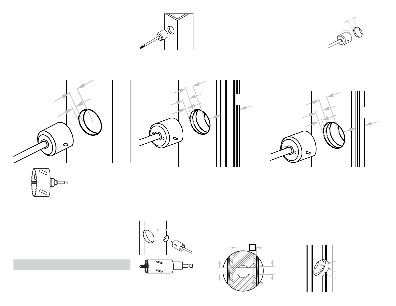
KNC C-54BL User manual

PATENT PENDING
KNCROWDER.COM 1—866—999—1562
PAGE 1 OF 6
Installation is based on barn door application where doors are hung on the outside of the room.
• Install lock inside the jamb wall behind the barn door
• Install trim plate on the jamb wall facing the opening
• Install strike with an emergency release on the barn door
• Adjustable strike for door thickness from 1 3/8 in [34.9 mm] to 2 1/4 in [57.1 mm]
Parts’ List
with Face Fixing Trim Plate
C-54BL Round Barn Door Lock
Barrier-Free (ADA Compliant)
Installation Instructions
Items No. Parts Description
Trim Parts 1Face Fixing Trim with
Spindle
1 each
2M4 x 50 Slotted Head
Screws
2 each
Lock 3Barn Door Lock 1 each
4M4 x 40 Wood
Screws
2 each
5Lock Bracket 1 each
Strike 6Dust Proof Strike 1 each
7Washer 2 each
8Sleeve 1 each
9Hollow Screw 1 each
Others 10 Decorative Cap 1 each
11 Emergency Key 1 each
-Door Prep Template 1 each
-Installation Instruction 1 each
11
10
9
8
7
6
3 5
4
1
2
Wall Conditions and Tools Suggestion
Most of the drywall will have corner bead in steel or vinyl; it’s strongly recommended to use a Hole Saw to cut the holes for
installing locks and trim plates. Hole Saw for steel will also help cut through any screws inside drywall or wood stud to make
the installation job run faster.
Tools required (not supplied)
Stud Finder
Level
T-Square
2 1/8 in Hole Saw
1 1/4 in Hole Saw
1 in Hole Saw
1/8 in Drill Bit
1/4 in Drill Bit
Wall Thickness
Lock Bolt No. Backset
Wall
Thickness
Typical
Wall Studs
C-54BL 2.25 in
[57.1 mm]
4.5 in
[114 . 3 mm]
2 x 4

DETAIL C200 NEW
SCALE 1 / 3
DETAIL C-913 GUIDE
SCALE 1 / 3
DETAIL C-913D-134 GUIDE
SCALE 1 / 3
DETAIL C-200 GUIDE NEW
SCALE 1 / 3
DETAIL C-1203 1.75"
SCALE 1 / 3
DETAIL C-1203 1.375"
SCALE 1 / 3
DETAIL C-1204 1.75"
SCALE 1 / 3
DETAIL C-913D-138 GUIDE
SCALE 1 / 3
DETAIL C-200D-134 GUIDE
SCALE 1 / 3
DETAIL C-200D-138 GUIDE
SCALE 1 / 3
DETAIL C-1204 1.375"
SCALE 1 / 3
DETAIL C-1205
SCALE 1 / 3
DETAIL CGGS-GUIDE
SCALE 1 / 3 DETAIL C-913-2NRW GUIDE
SCALE 1 / 3
DETAIL C-913-2 GUIDE
SCALE 1 / 3
DETAIL C-913-4 GUIDE
SCALE 1 / 3
POCKETOPENING
RECOMMENDED MINIMUM OVERLAP
IN POCKET: 2 in [50.8 mm]
POCKETOPENING
OPENED POSITION
WALL WHERE DOOR OPENS TOOPENING
RECOMMENDED MINIMUM OVERLAP
OF DOOR ON WALL: 2 in [50.8 mm]
RECOMMENDED OVERLAP
ON STRIKE SIDE: 2 in [50.8 mm]
OPENED POSITION
CLOSED POSITION
CLOSED POSITION
BY-PASS OPENING WIDTH
RECOMMENDED MINIMUM OVERLAP
OF BY-PASSING DOORS: 2 in [50.8 mm]
CENTER TO CENTER OF TRACK
BASED ON DOOR THICKNESS
RECOMMENDED MINIMUM OVERLAP
OF BY-PASSING DOORS: 2 in [50.8 mm]
CENTER TO CENTER OF TRACK
BASED ON DOOR THICKNESS
BY-PASS OPENING WIDTH
CLOSED POSITION
CLOSED POSITION
RECOMMENDED STRIKE
DEPTH: 1/2 in [12.7 mm]
POCKETOPENING
RECOMMENDED MINIMUM OVERLAP
IN POCKET: 2 in [50.8 mm]
POCKETOPENING
OPENED POSITION
CLOSED POSITION
RECOMMENDED STRIKE
DEPTH: 1/2 in [12.7 mm]
WALL WHERE DOOR OPENS TOOPENING
RECOMMENDED MINIMUM OVERLAP
OF DOOR ON WALL: 2 in [50.8 mm]
RECOMMENDED OVERLAP
ON STRIKE SIDE: 2 in [50.8 mm]
OPENED POSITION
CLOSED POSITION
KNCROWDER.COM 1—866—999—1562
PAGE 2 OF 6
Note: While door is fully closed, measure overlap on side
where lock is to be installed. For casing less than 1 5/8 in
[41.2 mm], door overlap must be at least 3 in [76.2 mm].
Align strike with lock.
Note: If lock bore center location is 2.125 in [53.9 mm] or
more from edge of opening, use stud finder to ensure there
are at least two studs stacked behind lock bore center.
Extended spindle and fixing screws may be required.
Contact KN Crowder to order an extension kit.
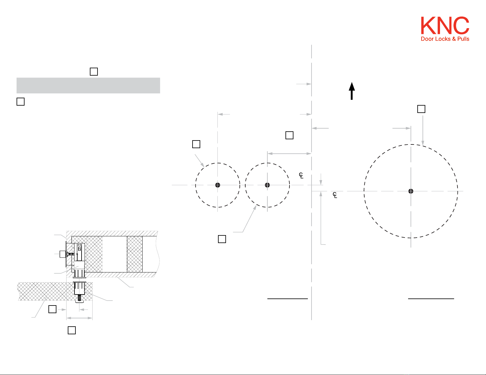
Step #2:
Verify wall thickness is
minimum 4.5 in [114.3 mm]
thick for KNC’s C-54BL
ADA barn door lock. There
is no maximum thickness
minimum stud size: 2x4,
backset: 2.25 in [57.1 mm]
Drywall Opening Opening with casing greater than 1 5/8 in [41.2 mm] Opening with casing less than 1 5/8 in [41.2 mm]
Installation Steps
For drywall opening with 0.5 in [12.7 mm] drywall (gypsum
board), minimum 2 in [50.8 mm] door overlap is needed to
install C-54BL. The lock bore center must be at least 1 in
[25.4 mm] from wall edge; align strike with lock.
Choose center hole location based on aesthetic
preference; must be at least 1 in [25.4 mm] from the edge.
Choose center hole
location based on your
aesthetic preference, must
be at least 1 in [25.4 mm]
from the edge.
Do not install lock on casing that is less than 1 5/8 in
[41.2 mm] wide. Drill lock bore at least 2.25 in [57.1 mm]
from edge. For this type of installation, door overlap must
be at least 3 in [76.2 mm]. Align strike with lock.
0.5 in
casing
0.5 in drywall 1.5 in
wood x 2
Door Door Door
min. 1 in
[25.4 mm]
min. 1 in
[25.4 mm]
≥1 5/8 in
[41.2 mm]
2.25 in
[57.1 mm]
to 2.5 in
[63.5 mm]
<1 5/8 in
[41.2 mm]
42 in [1066 mm]
42 in [1066 mm]
42 in [1066 mm]
42 in
[1066 mm]
lock
trim
0.141 in [3.5 mm]
centers offset
Step #3:
Remove barn door. Use the
template to mark pilot hole.
Note: The bore hole on the
jamb side is offset 3.5 mm
(approximately 0.125 in)
lower than wall-side bore.
4.5 in [114.3 mm]
6.5 in [165.1 mm]
2.25 in
[57.1 mm]
Jamb
Trim Face Bore
Step #1:

KNCROWDER.COM 1—866—999—1562
PAGE 3 OF 6
Step #4:
Before drilling, cover area around the bore hole with
masking tape to prevent the drywall from chipping or
cracking. With a Ø2 1/8 in hole saw, drill on jamb side in
accordance with following steps.
Without casing:
A. Drill through drywall approximately 0.5 in [12.7 mm] to
locate first wood stud.
B. Continue drilling 1 in [25.4 mm] into the stud.
Note: Do not exceed depth of wood stud when drilling. Minimum 0.25 in [6.3 mm] or thicker wood backing is required to support the lock.
For drywall openings protected with steel corner beads, use metal hole saw for cleaner and faster installation.
With casing 1 5/8 in [41.2 mm] or wider:
A. Drill through casing and drywall approximately 1 in
[25.4 mm] to locate the first wood stud.
B. Continue drilling 1 in [25.4 mm] deep into stud.
With casing less than 1 5/8 in [41.2 mm]:
A. Drill through casing and drywall approximately 1 in
[25.4 mm] deep to locate the first wood stud.
B. Continue drilling 1.75 in [44.5 mm] deep into the stud.
This will give you a 2.25 in [57.1 mm] deep bore to
accommodate the lock installed next to casing.
Step #5:
Double check lock bore distance from Step 1. Refer to template markings to ensure both lock and strike pilot holes are within door overlap requirements. Keep 0.375 in [9.5 mm] safety
margin to edges.
Moulded casing with uneven surface:
At pilot center mark, use Ø1 1/4 in hole saw to drill to a depth of 0.375 in [9.5 mm]. Use
Ø1 in hole saw at same center mark to drill hole to correct bore hole depth.
Note: Do not drill too deep, you may damage the wall on the other side.
Lock Part No. Backset Bore Hole Depth
C-54RBL 2.25 in [57.1 mm] 3.25 in [82.5 mm]
Drywall or flat casing openings:
Use a 1 in [25.4 mm] hole saw to cut lock bore hole to
depth as shown in chart.
Note: Hole saw for metal should be used for drywall with
steel corner bead.
Note: If there is a gap between the drywall and the stud,
measure the distance and add to the bore hole depth. Hole
depth must accommodate lock barrel preparation in step 6.
You can deepen trim bore as needed after that step.
0.375 in
[9.5 mm]
Depth
1 in
[25.4 mm] 3/8 in [9.5 mm]
Ø1 1/4 in Ø1 1/4 in
Ø1 in
0.375 in [9.5 mm]
A
1 in [25.4 mm]
1 in [25.4 mm]
1 in [25.4 mm]
1 in [25.4 mm]
1.75 in [44.4 mm]
1.5 in
[38.1 mm]
Gap
0.5 in [12.7 mm] 0.5 in [12.7 mm]
0.5 in [12.7 mm]
≥1 5/8 in
[41.2 mm]
<1 5/8 in
[41.2 mm]

KNCROWDER.COM 1—866—999—1562
PAGE 4 OF 6
Step #6:
For drywall and casing less than 1 5/8 in [41.2 mm]:
A. Insert bracket into trim bore
B. Insert lock bolt into lock bore and fit into bracket slot.
For moulded casing with uneven surface:
A. Insert 0.25 in [6.3 mm] spacer provided with lock into
the 1.25 in [31.7 mm] recess first.
B. Insert bracket into trim bore.
C. Insert lock bolt and spacer into lock bore and fit
into bracket slot.
Step #7:
Ensure spindle hub is at center of trim bore. Use spindle or screwdriver to test bolt
retraction; if not smooth, troubleshoot as follows:
1. Check 2 1/8 in [53.9 mm] trim bore dimensions.
2. Ensure hole is free of debris.
3. Make sure 1 in [25.4 mm] lock bore is perpendicular to trim bore.
4. Check lock by removing it from bore and throwing the bolt. Adjust wall prep as needed.
Step #8:
Fasten the two wood screws inside the trim bore hole through lock body and into wood
stud.
Arrow should point up
2.25 in [57.1 mm]
3.5 in [88.9 mm]

PATENT PENDING
KNCROWDER.COM 1—866—999—1562
PAGE 5 OF 6
Step #14:
With the pilot hole as a guide, use a Ø1/4 in bit to drill a
hole from the outside to connect with the strike bore hole.
Note: Standard barn door to wall clearance is approximately 0.375 in [9.5 mm] to 0.5 in
[12.7 mm]. Install additional spacer as needed behind the strike faceplate if the door to wall
clearance is over 0.5 in [12.7 mm]. Additional spacers can support maximum clearance of
0.75 in [19 mm] between door and wall.
Step #13:
Using the strike center position as a guide, drill a pilot hole
through the door with a Ø1/8 in drill bit from strike side.
With the pilot hole as guide, use a Ø1 in hole saw to drill a
1.25 in [31.7 mm] deep hole.
Note: do not drill through the door!
Step #9:
Cut spindle and screw to accommodate wall side backset.
Edge to Lock Center Spindle Length Screw Length
1 in [25.4 mm] 1.25 in [31.7 mm] 0.813 in [20.6 mm]
1.25 in [31.7 mm] 1.5 in [3 8 .1 mm] 1.063 in [26.9 mm]
1.5 in [3 8 .1 mm] 1.75 in [44.4 mm] 1.313 in [33.3 mm]
1.75 in [44.4 mm] 2 in [50.8 mm] 1.563 in [39.6 mm]
2 in [50.8 mm] 2.25 in [57.1 mm] 1.813 in [46 mm]
2.25 in [57.1 mm] 2.5 in [63.5 mm] 2.063 in [52.3 mm]
2.5 in [63.5 mm] 2.75 in [69.8 mm] 2.313 in [58.7 mm]
H
H
L
L
B
B
Step #10:
Insert trim into spindle
hole. Use thumb turn to
test lock bolt movement.
Step #11:
Fasten trim screws until
trim is tight to jamb
surface.
Note: do not over tighten.
Step #12:
Move door to closed
position and throw the
lock bolt to mark the exact
strike center position.
This location must be a
minimum of 1 in [25.4 mm]
to the edge of the door.
Marking
Minimum 0.5 in [12.7 mm]
Maximum 0.75 in [19 mm]
Ø1 in
Ø1/4 in
Ø1/4 in
Ø1 in
Ø1 in
Ø1/8 in
1.25 in
[31.7 mm]
Door
outside
face

1220 Burloak Drive, Burlington, Ontario, Canada, L7L 6B3
© 2020-2022 K.N. Crowder Mfg. Inc. All Rights Reserved.
PAGE 6 OF 6
Step #18:
Use release key, provided with lockset, to push through
center hole on release to push lock bolt back and unlock
door.
Step #17:
Install break-away screw and tighten with Allen wrench.
Screw on decorative cap by hand.
Note: do not over tighten.
DoorDoor
Step #16:
Cut break-away screw to appropriate door thickness.
Note: do not over tighten.
Door thickness
Length without
spacer
Length with
spacer
1 3/8 in
[34.9 mm]
11/16 in
[17. 4 mm]
15/16 in
[23.8 mm]
1 3/4 in
[44.4 mm]
1 3/32 in
[27.7 mm]
1 5/16 in
[33.3 mm]
C
11/16 in [17.4 mm]
15/16 in [23.8 mm]
1 3/32 in [27.7 mm]
1 5/16 in [33.3 mm]
Open
Step #15:
Install the 1 in [25.4 mm] dust-proof strike with the 0.25 in
[6.3 mm] release screws on the outside.

KNCROWDER.COM 1—866—999—1562
PAGE 1 OF 2
C-54RBL Round ADA Barn Door Lock
Left Handing
Door and Wall Prep Template
Part No. Backset
Min. Wall
Thickness
C-54RBL 2.25 in
[57 mm]
3.5 in
[89 mm]
4.5 in
[114 mm]
Wall Jamb
Up
Outward crease line
Maximum 2.125 in [54 mm]
2.25 in [57 mm] backset
Ø2 1/8 in
Depth = + 0.5 in [12.7 mm]
Ø1 in
Depth =
See table above
Ø1 in
Depth =
See table above
of trim
0.141 in [3.5 mm]
centers offset
of lock
Minimum 1 in
[25 mm]
B
B
B
A
A
represents the distance from the edge of wall to center
of lock bore
Prep LOCK bore on wall side Prep TRIM bore on jamb side
For opposite hand, please see reverse side.
Template dimensions do not provide allowances for gaps between wall studs and drywall.
Refer to installation instructions for more details.
A
Wall
Strike
Min. 2 in [50.8 mm]
Overlap = + 1 in [25.4 mm]
Door
Lock
Trim
Jamb
B
B

1220 Burloak Drive, Burlington, Ontario, Canada, L7L 6B3
© 2020-2022 K.N. Crowder Mfg. Inc. All Rights Reserved.
PAGE 2 OF 2
C-54RBL Round ADA Barn Door Lock
Right Handing
Door and Wall Prep Template
Part No. Backset
Min. Wall
Thickness
C-54RBL 2.25 in
[57 mm]
3.5 in
[89 mm]
4.5 in
[114 mm]
Brepresents the distance from the edge of wall to center
of lock bore
WallJamb
Up
Outward crease line
Maximum 2.125 in [54 mm]
2.25 in [57 mm] backset
Ø2 1/8 in
Depth = + 0.5 in [12.7 mm]
Ø1 in
Depth =
See table above
Ø1 in
Depth =
See table above
of trim
0.141 in [3.5 mm]
centers offset
of lock
Wall
Strike
Min. 2 in [50.8 mm]
Overlap = + 1 in [25.4 mm]
Door
Lock
Trim
Jamb
Minimum 1 in
[25 mm]
B
B
B
B
A
A
Prep LOCK bore on wall sidePrep TRIM bore on jamb side
For opposite hand, please see reverse side.
Template dimensions do not provide allowances for gaps between wall studs and drywall.
Refer to installation instructions for more details.
A
Popular Door Lock manuals by other brands

Extel
Extel WECA 109057 Installation and operation manual

Saflok
Saflok Quantum ädesē RFID installation instructions

Lockly
Lockly DEADBOLT EDITION 7S installation guide

Schlage
Schlage XE360-M Series installation instructions

Samsung
Samsung Smart Door Lock SHS-3320 user guide

Assa Abloy
Assa Abloy effeff ANYKEY Programming and operation instructions