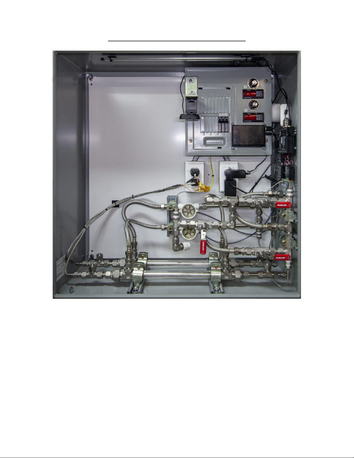
Sentinel Initial Installation
In order to prepare your Sentinel for operation the following steps must be taken:
1) Connect adequate power to the unit. Sentinel Model B-2 requires 120vac, 20 amps power. A 30amp inlet plug is
provided and must be wired prior to installation.
2) Connect Cooling Water inlet to adequate sample line. Approximately 6 gpm.
3) Connect Cooling Water outlet to return cooling water to outlet or drain.
4) Connect Process Fill Column & Process Vent tubing to the exterior of unit.
5) Place or mount the unit to a stable location.
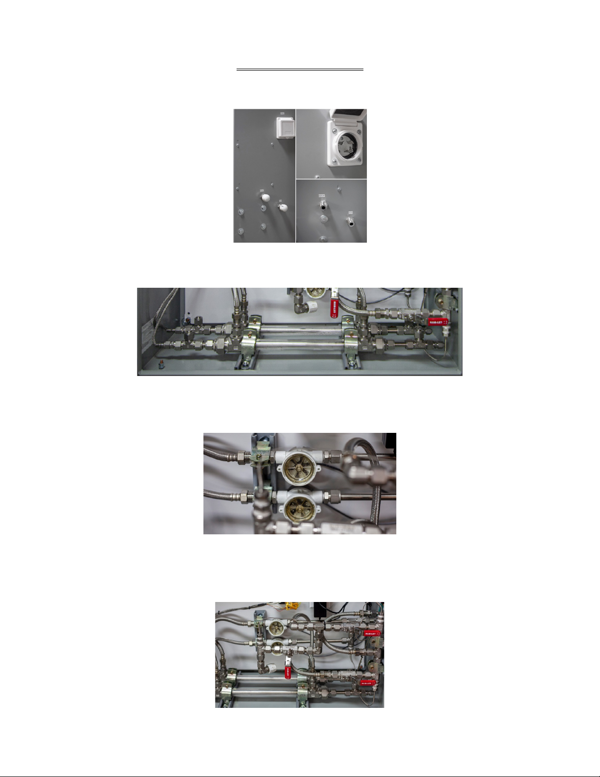
Power Inlet Plug Wiring Instructions:
Warning: To prevent electrocution make sure the cable is not connected to a power source before installing the plug or
connector.
Failure to comply with the following instructions could cause an electrical failure or fire.
1) Check to see the rating on the plug or connector is correct for the installation.
2) Select a cable of suitable amp capacity, service, and temperature rating. The plugs and connectors are designed for
use with round jacketed, hard usage cable (S-type, 8-3AWG.)
3) Remove the housing by loosening the three screws on the face of the device and slide it over the cable. If a
weather resistant boot is used, slide this over the cable before the housing. Strip the outer jacket of the cord 1.25”
and 5/8” of the inner insulation to expose the copper wire. Make sure the wire is clean and a bright copper color.
If necessary, cut back the wire until clean wire is uncovered. Do not solder the ends of the wires.
4) Insert all the wires into the proper color coded terminal pockets.
5) Tighten the terminal screws to 20 in-lbs torque. Make certain there is no wire insulation clamped inside any
terminal and there are no stray wire strands outside the terminals.
6) By alternating between the two screws, tighten the strain relief screws to 14 in-lbs torque so the strain relief is
even and securely grips the cable jacket.
7) Slide the housing over the plug or connector body and tighten the two assembly screws.
8) If a weather resistant boot is used, slide that over the complete assembly.
Prior to connecting the plug to the unit, ensure that all the breakers are in the off position and cooling water is blocked off
from the supply stream.
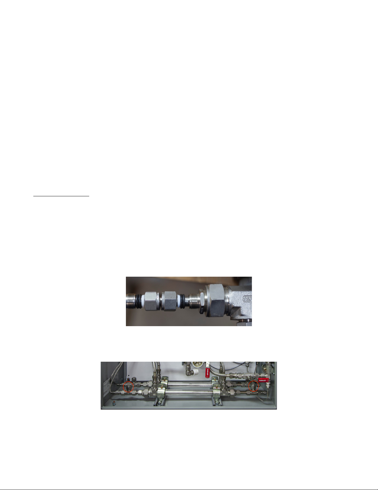
Cooling Water Inlet & Outlet Instructions:
Sentinel requires a cooling water sample line and drain. Optimal cooling water supply from the cooling tower is 6-10gpm.
Please contact us if you have a supply line that is below 6gpm. A return sample sent to the skid will assist achieving desired
higher skin temperatures due to the elevated heat. The sample should be as representative as possible, so the actual
performance of the cooling water can be monitored. The connection to the bulkhead for the cooling water inlet and outlet
is ½” Male NPT.
Additional cooling water items to consider:
- Ensure the sample line is not too long so the chlorine residual is not depleted by the time it reaches the Sentinel.
- Make sure that the pressure is not too low due to line loss. Low pressure can often be resolved with a common
hardware store booster pump, though normally only required in unusual circumstances.
- If the cooling water has debris in it, you likely will need a strainer. We have successfully utilized ¾” poly strainers
(80 mesh - 150psi) with the operation of the Sentinel.
The cooling water drain from the Sentinel can be routed back to the cooling tower or any other drain. Care should be
taken to provide an unobstructed flow from the unit to ensure adequate cooling water flow and associated velocity in the
exchangers.