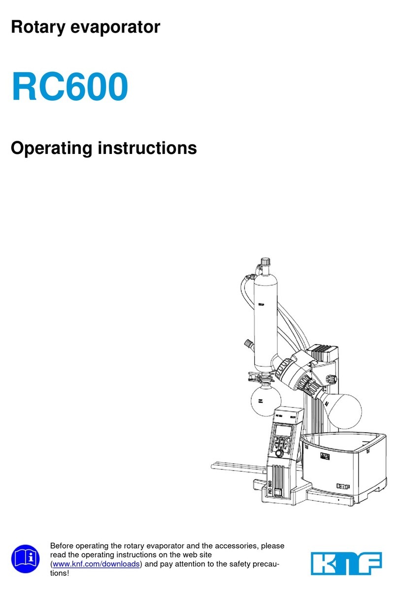
KNF Yamato RE212-G User manual

Rotary Evaporator
RE212-G
Instruction Manual
First Edition
Printed on recycled paper
Thank you for choosing RE series Rotary
Evaporators from KNF NEUBERGER GmbH /
Yamato Scientific Co., Ltd.
For equipment operation, please read and
become thoroughly familiar with this
instruction manual before use. Always keep
equipment documentation safe and close at
hand for convenient future reference.
Warning: Read instruction manual
warnings and cautions carefully
and completely before
proceeding.


TABLE OF CONTENTS
1. SAFETY PRECAUTIONS ........................................................................................................... 1
Explanation of Symbols ............................................................................................................ 1
Symbol Glossary ...................................................................................................................... 2
Warnings and Cautions ............................................................................................................ 3
Residual Risk Map ................................................................................................................... 5
List of Residual Risks ............................................................................................................... 6
Accessories .............................................................................................................................. 9
Peripheral equipment (sold separately) .................................................................................... 9
Control Unit ............................................................................................................................ 10
Display Characters ................................................................................................................. 10
3. PRE-OPERATION PROCEDURES .......................................................................................... 11
Installation Precautions .......................................................................................................... 11
Installation Procedure ............................................................................................................ 13
4. OPERATION PROCEDURES ................................................................................................... 21
Operation Procedure .............................................................................................................. 21
User Setting ........................................................................................................................... 22
Rotation Modes ...................................................................................................................... 23
Auto Inversion Time Setting ................................................................................................... 24
Auto-resume Function ............................................................................................................ 25
LED Brightness Setting .......................................................................................................... 26
Operation Start ....................................................................................................................... 27
Operation Stop ....................................................................................................................... 28
5. HANDLING PRECAUTIONS ..................................................................................................... 29
Warnings and Cautions .......................................................................................................... 29
6. MAINTENANCE PROCEDURES .............................................................................................. 30
Precautions before Inspection ................................................................................................ 30
Precautions in Daily Maintenance .......................................................................................... 30
Maintenance and Inspection .................................................................................................. 30
7. EXTENDED STORAGE AND DISPOSAL ................................................................................. 31
Extended Storage .................................................................................................................. 31
Disposal Considerations......................................................................................................... 31
8. TROUBLESHOOTING .............................................................................................................. 32
Reading Error Codes ............................................................................................................. 32
Troubleshooting Guide ........................................................................................................... 33
9. SPECIFICATIONS .................................................................................................................... 35
10. Consumables/Replacement Parts ....................................... Fehler! Textmarke nicht definiert.
11. BC102-G Instruction manual ................................................................................................... 37
Appearance ............................................................................................................................ 37
Accessories ............................................................................................................................ 38
WARNING.............................................................................................................................. 38
CAUTION ............................................................................................................................... 38
Installation Procedure ............................................................................................................ 39
Operation Procedure .............................................................................................................. 42
12. REFERENCE DATA ............................................................................................................... 43
Solvent Boiling Point .............................................................................................................. 43
13. LIST OF HAZARDOUS SUBSTANCES .................................................................................. 44
14. STANDARD INSTALLATION MANUAL .................................................................................. 45

1
1. SAFETY PRECAUTIONS
Explanation of Symbols

2
1. SAFETY PRECAUTIONS
Symbol Glossary
WARNING / CAUTION
General Danger!
Blast Hazard
Caution: Indoor
Use Only
RESTRICTION
General
Restriction
Do Not
Disassemble
ACTION
General Action
Required
Connect Ground
Wire Level Installation Disconnect Power Inspect
Regularly

3
1. SAFETY PRECAUTIONS
Warnings and Cautions
WARNING
Install in a location free of flammables and explosives.
Never install or operate unit in a flammable or explosive gas atmosphere.
See "LIST OF HAZARDOUS SUBSTANCES" (P.44 ) for information on flammable and
explosive gases.
Ground wire MUST be connected properly
・Connect power cable to a grounded outlet in order to avoid electric shock.
・Never connect ground wire to gas lines or water pipes. ・ Fire, accident or equipment
malfunction may result.
・Never connect ground wire to telephone grounding lines or to lightning conductor rods.
Fire or electric shock may result.
・ Never insert multiple plugs into a single outlet. Doing so may result in power cable
overheating, fire or drop in voltage.
Connect power cable properly
Insert power cable firmly into the AC adapter inlet. Failure to do so may result in
overheating, fire, and/or electric shock.

4
1. SAFETY PRECAUTIONS
Warnings and Cautions
Turn OFF (○) power immediately when an abnormality occurs.
If unit begins emitting smoke or abnormal odours for reasons unknown, turn OFF (○)
power immediately, disconnect power cable from power supply, and contact original
dealer of purchase for assistance.
Continuing to operate without addressing abnormalities may cause fire or electric shock,
resulting in serious injury or death. Never attempt to disassemble or repair unit. Repairs
should always be performed by a certified technician.
Handle power cable with care.
・Do not operate unit with power cable bundled or tangled. Operating unit with the power
cable bundled or otherwise tangled, may cause power cable to overheat and/or catch
fire.
・Do not modify, bend, forcibly twist or pull on power cable. Fire or electric shock may
result.
・Do not risk damage to power cable by positioning it under desks or chairs, or by allowing
it to be pinched in between objects. Fire or electric shock may result.
・Do not place power cable near kerosene/electric heaters or other heat-generating
devices. Doing so may cause power cable insulation to overheat, melt and/or catch fire,
which may result in electric shock.
・Turn OFF (○) power immediately and disconnect from facility terminal or outlet, if power
cable becomes partially severed or damaged in any way. Contact original dealer of
purchase for information about replacing power cable.
Failure to do so may result in fire or electric shock.
・Always connect power cable to appropriate facility outlet or terminal.
DO NOT disassemble or modify equipment
Never attempt to disassemble or modify unit. Doing so may cause malfunction, fire,
electric shock, or personal injury. Note that any malfunction resulting from unauthorized
modifications or customizations to unit will void the warranty.
Exercise caution when handling flammable chemicals.
Unit is NOT fire or blast resistant. When processing flammable samples, be sure to
provide adequate ventilation and not to allow anything that may be a source of fire or
ignition (static electricity, etc.) approached. Do not use this unit in an atmosphere of
substances shown in LIST OF HAZARDOUS SUBSTANCES (P.44). Never vaporize
explosive substances. Fire or explosion causing serious injury or death may result.
CAUTION
DO NOT operate equipment during thunderstorms
In the event of a thunderstorm, turn OFF (○) power and disconnect power cable
immediately. A direct lightning strike may cause equipment damage, fire or electric shock,
resulting in serious
injury or death.

5
1. SAFETY PRECAUTIONS
Residual Risk Map
These figures indicate positions of caution labels.
The numbers shown in the figure indicate the numbers listed in the "List of Residual Risks" in
this manual.
For details of individual residual risks, see the List of Residual Risks.
[]
* Contact us if the caution signs are no longer visible because the nameplate has
is peeled off or the text is no longer legible. We will send you a new nameplate.
(Chargeable)
Model/Rating label
10

6
1. SAFETY PRECAUTIONS
List of Residual Risks
List of residual risks (instructions for risk avoidance)
This list summarizes residual risks to avoid personal injuries or damages to properties during or related
to the use of equipment.
Be sure to fully understand or receive instructions on how to use, maintain and
inspect equipment before starting operation.
Loading/Installation
No.
Degree of
risks
Risk
description Protective measures taken by the user Relevant
page
1 WARNING Fire/
Electric shock
Install in a location free of flammables and
explosives.
P.3
2 CAUTION Fire/
Electric shock
Ground wire MUST be connected properly P.3
3 CAUTION Fire/
Electric shock
Connect power cable properly. P.3
4 WARNING Fire/
Electric shock
Turn OFF (○) power immediately when an
abnormality occurs.
P.4
5 WARNING Fire/
Electric shock
Handle power cable with care. P.4
6 WARNING Fire/
Electric shock
DO NOT disassemble or modify equipment. P.4
7 WARNING Fire Exercise caution when handling flammable
chemicals.
P.4
8 WARNING Fire Choose an appropriate installation site. P.11
9 WARNING Injury Install unit on a level surface. P.11
10 WARNING Fire/
Electric shock
Always connect power cable to appropriate
facility outlet or terminal.
P.12
11 WARNING Fire/
Electric shock
Install in a dry location. P.12
12 WARNING Injury Pay attention to the surroundings whenever
operating jack.
P.12
13 WARNING Injury Be aware that slide panel may spring up P.13
14 WARNING Injury Install glassware and piping with slide panel lifted
up.
P.13
15 CAUTION Injury Use caution when handling glassware P.15
Use
No.
Degree of
risks
Risk
description Protective measures taken by the user Relevant
page
16 WARNING Explosion/
F
ire
Exercise caution when handling flammable
chemicals.
P.29
17 WARNING Fire/
Electric shock
Turn OFF (○) power immediately when an
abnormality occurs.
P.29
18 WARNING Fire/
Electric shock
DO NOT operate equipment during
thunderstorms
P.4
19 CAUTION Injury Select appropriate gasket for organic solvents P.29

7
1. SAFETY PRECAUTIONS
List of Residual Risks
Daily inspection/maintenance
No.
Degree of
risks
Risk
description Protective measures taken by the user Relevant
page
20 WARNING Fire/
Electric shock
Remove power cable for inspection and
maintenance.
P.30
21 WARNING Fire/
Electric shock
NEVER disassemble or modify unit P.30
Extended storage/disposal
No.
Degree of
risks
Risk
description Protective measures taken by the user Relevant
page
22 WARNING Fire/
Electric shock
Turn OFF (○) power and disconnect power
cable.
P.31
23 CAUTION Injury Do not leave unit in a location where children
may have access
P.31

8
2. COMPONENT NAMES AND FUNCTIONS
Main Unit
Tilt adjustment screw
Jack handle
Bath guide
Receiving flask
Power cable
Level adjuster
Cooling nozzle (IN)
(black cap)
Cooling nozzle (OUT)
(black cap)
Cooling condenser
(type F)
Evaporation flask
Slide panel
Control panel
Stand base
Ball joint clamp
Condenser insulation
Sample inlet
Refill Valve
Flask clip
AC adapter
DC jack
VR connection terminal (mini-DIN 8P)
Vacuum nozzle (grey cap)
Motor box
Condenser bracket
Mini DIN connector
* Used for connecting Protection Cover (BC102-
G)

9
2. COMPONENT NAMES AND FUNCTIONS
Accessories
Check before operation that all the accessories are complete.
Contact original dealer of purchase if anything is missing.
① Power cable (approx.
0.7 m)
② AC adapter
③ Bath guide
④ Rear cover
⑤ Tape fastener
Used for binding
condensor
and hoses
⑥ Joint nut
⑦Condenser bracket
⑧Handle extension
adapter
⑨ Instruction manual
* Check the accessories for each condenser unit on the list of condenser unit accessory included with
condenser unit.
Peripheral equipment (sold separately)
Protection Cover
(BC102-G/255698)
It covers the water chamber of BM312-G /
BO312-G and suppresses splashing due to
the rotation of the flask.
Refer “11. BC102-G instruction manual
(P.41)”

10
2. COMPONENT NAMES AND FUNCTIONS
Control Unit
No.
Panel item
Description
① RPM display Shows rotation speed reading and setting, and each
parameter.
② Power key Press to turn ON (|) or OFF (○) power.
③ Run/Stop key Press to start or stop rotation.
④ Run/Stop lamp Illuminates during operation.
⑤ Control knob Turn to increase or decrease set value, scroll items in user
setting, and press to switch or finalize settings.
⑥ Fwd lamp Forward lamp; illuminates in forward rotation mode
⑦ Rev lamp Reverse lamp; illuminates in reverse rotation mode
⑧ AutoR lamp Auto Rotation lamp; illuminates in auto inversion mode
⑨ Sync lamp Synchro lamp; not used for this unit.
Display Characters
All characters displayed when making settings are defined as follows
Character
Letters
Description
rot Indicates rotation mode setting.
See “Rotation Modes” (P. 23)
SEC Indicates time setting for automatic inversion.
See “Timed Auto Inversion Mode” (P. 24)
Pon
Indicates setting of the behavior of unit at power loss restoration.
See "Auto-resume Function" (P.25)
dSP
Indicates LED brightness setting.
See "LED Brightness Setting" (P.26)
Fwd Rev AutoR Sync
①
②
③
⑤
⑥
⑦ ⑧
⑨
④

11
3. PRE-OPERATION PROCEDURES
Installation Precautions
Choose an appropriate installation site.
DO NOT install unit:
・ where installation surface is not completely level, not even or not clean.
・ where flammable or corrosive gases/fumes may be present
・ where external temperature will exceed 35°C, will fall below 5°C or will fluctuate largely.
・ where liquid is assumed to splash on unit
・ in excessively humid or dusty locations.
・ in direct sunlight or outdoors.
・ where there is constant vibration.
・ in direct contact with the outside air
・ where power supply is erratic.
・ where there is combustible material nearby.
・ in the proximity of, particularly directly below a fire alarm.
・ where there is a risk of freezing or condensation.
Install unit, including glass set, in a location with sufficient space as specified below.
Install unit on a level surface.
Install unit on a level and even surface. Failure to do so may cause abnormal vibrations or
noise, possibly resulting in complications and/or malfunction.
Use level adjuster on the back of unit
when unit still wobbles despite level
installation.
Turn the wheel left to raise, turn it
right to lower.
RE unit
5 cm or more
5 cm
or more
5 cm
or more
5 cm or more
Level adjuster
Move upward
30 cm or more
Ceiling
Floor
RE unit

12
3. PRE-OPERATION PROCEDURES
Installation Precautions
Connect the power supply of this unit to BM312-G (BO312-G).
The power cable attached to this unit is exclusively for BM312-G (BO312-G) connection.
When using it, connect it to BM312-G (BO312-G) and do not use any cable other than the
dedicated cable.
Install in a dry location.
Install unit where it will be free from
liquid spray and other moisture.
Failure to do so may result in control
mechanisms becoming wet, causing
malfunction, electric shock and/or fire.
Pay attention to the surroundings whenever operating jack.
Do not place any objects under the slide
panel. Such objects may cause damage
to unit or personal injury when using the
jack handle.
Always lower the slide panel slowly to
prevent damage to glassware on contact
with the bath

13
3. PRE-OPERATION PROCEDURES
Installation Procedure
Be aware that slide panel may spring up
Slide panel on this unit employs a spring-loaded jack to lift it up.
The spring tension is adjusted to achieve balance when all the connection with glassware
and piping are made.
The panel jumps up when releasing the lock of the jack without glassware mounted.
Be sure to hold
the
t
op of the slide panel by hand whenever re
leasing the lock.
Always install glassware and piping with the slide panel lifted up.
If the lock of the jack is unintentionally released while setting up glassware and piping,
there is a risk of damage to glassware, and/or personal injury.
1. Jacking up
(1) Release the lock by turning jack handle
counterclockwise while holding the slide panel
top.
Hold the slide panel tightly or it may jump up.
(2) Lift up the slide panel to top, turn the handle
clockwise to lock.
2. Motor box tilt adjustment
(1) Hold motor box by hand and turn tilt
adjustment screw counterclockwise to
release the lock.
(2) Motor box can now rotate. Rotate the box to
the position for use and turn tilt adjustment
screw clockwise to lock the driving unit.
(3) Adjust the control panel angle for better
visibility
Tilt the driving unit at about 30° before
installation.
Hold here by hand
FREE
LOCK
FREE
LOCK
Jack handle
Slide panel
FREE
LOCK
Tilt adjustment screw
Motor box
Control panel
30°

14
3. PRE-OPERATION PROCEDURES
Installation Procedure
3. Installing Vapor Tube
(1) Remove joint nut
Press in the lock pin with the thumb to lock
the rotary part. Take off joint nut by turning it
counterclockwise with the other hand.
(2) Install Vapor Tube
Insert Vapor Tube into the Vapor Tube
opening until it clicks, while holding motor
box tightly with the other hand.
(3) Replace joint nut
As with step (1), press in the lock pin to lock
the rotary part. Screw in joint nut clockwise
with the other hand.
(4) Attach flask removal tool
(included with glass set)
① Fit flask removal tool over Vapor Tube.
② Pinch flask removal tool and slip it in joint
nut.
* There is a direction for flask removal tool.
Pawl should come to the joint nut side.
Flask removal tool facilitates removing flask
and Vapor Tube. See “Operation Stop”
(P.28)
Lock pin
Lock pin Joint nut
Joint nut
Flask removal tool
Threaded Vapor
Tube opening
Vapor Tube
Joint nut
Pawl
Flask removal tool
①

15
3. PRE-OPERATION PROCEDURES
Installation Procedure
Use caution when handling glassware
Any damage on glassware may lead to serious accidents. Check glassware for damage
before operation.
4. Attaching condenser nut
Attach condenser nut for mounting condenser
on main unit
① Pass condenser nut on condenser flange.
② Put coil ring over condenser flange.
③ Lightly pull on condenser nut to ensure it
does not come off condenser flange.
Cooling condenser
Condenser flange
Condenser nut Coil ring
①
②

16
3. PRE-OPERATION PROCEDURES
Installation Procedure
5. Installing vacuum seal
Pay attention to the direction of vacuum seal.
Installing vacuum seal in the opposite direction may lead to poor vacuum, or may wear the
seal, resulting in damage to
driving unit.
Install vacuum seal.
Fit vacuum seal into the housing by
passing it on Vapor Tube with the side
where the spring is visible facing motor
box.
Be sure to install vacuum seal after Vapor
Tube is set, to prevent damage to vacuum
seal.
Make pipe connection properly
Be sure to install all tubing in right positions. Improper connection and looseness of nozzle
caps may cause leakage or damage to
peripherals.
6. Installing nozzle unit
Nozzle unit has two types, with gre
y cap and
black cap.
Grey: for vacuum line
Black: for cooling water line
Three parts of “Nozzle”, ”Nozzle cap”,
and ”Nozzle gasket” comprise the nozzle
unit.
Ensure that nozzle gasket is placed in
nozzle cap.
① Screw down nozzle cap against nozzle
receptacle on cooling condenser.
② Turn nozzle cap clockwise to fasten.
Nozzle unit sectional diagram
Cooling
condenser
Vacuum seal
Vapor Tube
Vacuum seal
Housing
Nozzle receptacle
(GL14)
Nozzle cap
Nozzle
Nozzle gasket
Vacuum line
Cooling water line

17
3. PRE-OPERATION PROCEDURES
Installation Procedure
7. Installing bath guide
Attach supplied bath guide to main unit stand
base.
(1) Insert bath guide into the slot on bottom of
stand base.
The bath guide slots are positioned on
both right and left. Choose the side on
which an evaporation flask is to be
attached.
8. Installing condenser bracket
(1) Remove two cap bolts (black) on motor
box with supplied hex wrench.
(2) Attach condenser bracket with the cap
bolts removed.
Bath guide
Bath guide slot
Cap bolt (black)
Hex wrench (included)
Condenser bracket
Motor box
This manual suits for next models
1
Table of contents
Other KNF Laboratory Equipment manuals
Popular Laboratory Equipment manuals by other brands

Speakman
Speakman SE-4300 GRAVITYFLO instructions

THORLABS
THORLABS Vytran FFS2000 Series user guide

Metkon
Metkon FORCIPOL Series Operation & instruction manual

Thermo Electron
Thermo Electron FL40 Service manual

Phcbi
Phcbi MDF-C8V1 operating instructions

Monmouth Scientific
Monmouth Scientific PCR650 Operating and maintenance manual