Metkon FORCIPOL Series Administrator Guide
1
metkon.com
OPERATION & INSTRUCTION MANUAL
MODULAR GRINDING AND POLISHING SYSTEM

2
EC Declaration of Conformity
Manufacturer : Metkon Instruments Inc.
Address : Demirtas Dumlupinar Organize Sanayi Bolgesi
Ali Osman Sonmez Cd. No: 14 Bursa / TURKEY
Model No : FORCIPOL 102/202
Herewith declares that;
Metallographic Grinding & Polishing Machine
is in conformity with the provisions of the Machinery Directive (directive 2006/42/EEC), as amended, and with national
implementing legislation;
is in conformity with the provisions of the Low Voltage Directive (directive 2014/35/EU), as amended, and with national
implementing legislation;
is in conformity with the provisions of the EMC Directive (directive 2014/30/EU), as amended, and with national
implementing legislation;
And furthermore declares that
the following (parts/clauses of) standards have been applied
EN ISO 12100:2010, TS EN 60204-1, TS EN IEC 61000-6-2, TS EN 61000-6-4
Authorized Person: ERCIN SENAY
Position: Manager of Research and Development Department
Year: 2019
Bursa / Turkey

3
Index
DESCRIPTION ............................................................................................................................ 6
Design .....................................................................................................................................................................................6
Technical Data ........................................................................................................................................................................7
Warranty .................................................................................................................................................................................8
Safety Precautions ..................................................................................................................................................................8
INSTALLATION & SET UP........................................................................................................... 9
Unpacking & Checking Contents of Package ...........................................................................................................................9
Step by Step Unpacking...........................................................................................................................................................9
Installation and Set-Up ...........................................................................................................................................................9
Electrical Installation ........................................................................................................................................................................ 10
Water & Cable Connections................................................................................................................................................................ 11
Assembling FORCIMAT 52/102 Automatic Head.................................................................................................................................12
Air Connection...................................................................................................................................................................................13
Assembling Sample Holders.............................................................................................................................................................. 14
Adjusting the Height of FORCIMAT 52/102 Head............................................................................................................................... 14
Fixing and Releasing the Automatic Head ..........................................................................................................................................15
LEVOMAT Specimen Loading Fixture................................................................................................................................................ 16
DOSIMAT Peristaltic Fluid Dispenser..................................................................................................................................................17
Installation of DOSIMAT 12/52/102 ....................................................................................................................................................17
To Make DOSIMAT Ready for Operation............................................................................................................................................ 18
Cleaning DOSIMAT Hoses...................................................................................................................................................................19
Platen Installation..............................................................................................................................................................................19
Using Different Diameter Discs ..........................................................................................................................................................19
Optional Recirculating Cooling System (ENVIRO) ...............................................................................................................................19
Noise Level ........................................................................................................................................................................................19
CONTROL PANEL (FORCIPOL Control Unit)............................................................................. 20
Control Button Functions ......................................................................................................................................................20
CONTROL PANEL (FORCIMAT 52) ........................................................................................... 20
Control Button Functions ......................................................................................................................................................20
CONTROL PANEL (DOSIMAT 12)...............................................................................................21
Control Button Functions ...................................................................................................................................................... 21
CONTROL PANEL (DOSIMAT 52) ..............................................................................................21
Control Button Functions ...................................................................................................................................................... 21
CONTROL PANEL (DOSIMAT 102) ........................................................................................... 22
TOUCH SCREEN CONTROL PANEL (FORCIMAT 102) ............................................................... 22
Control Button Functions ......................................................................................................................................................22
Password List........................................................................................................................................................................23
Operation Parameter Ranges ................................................................................................................................................23
OPERATION (FORCIPOL Control Unit)..................................................................................... 24

4
Setting Parameters ................................................................................................................. 24
Setting Disc Speed ............................................................................................................................................................................ 24
Setting Disc Turning Direction .......................................................................................................................................................... 24
Setting Operation Time ..................................................................................................................................................................... 24
Cooling Water ................................................................................................................................................................................... 24
Cooling Water Activation Modes....................................................................................................................................................... 24
Disc Cleaning and Drying Function ................................................................................................................................................... 24
Changing Parameters of Disc Cleaning and Drying Function............................................................................................................. 24
Start and Stop ................................................................................................................................................................................... 24
OPERATION (FORCIMAT 52).................................................................................................... 25
Setting Parameters ................................................................................................................. 25
Setting Disc Speed ............................................................................................................................................................................ 25
Setting Head Speed........................................................................................................................................................................... 25
Opposite Rotation Direction.............................................................................................................................................................. 25
Setting Operation Time ..................................................................................................................................................................... 25
Cooling Water ................................................................................................................................................................................... 25
Cooling Water Activation Modes....................................................................................................................................................... 25
Disc Cleaning and Drying Function ................................................................................................................................................... 25
Changing Parameters of Disc Cleaning and Drying Function............................................................................................................. 25
Manual Operation............................................................................................................................................................................. 26
Pistons Up/Down.............................................................................................................................................................................. 26
Start and Stop ................................................................................................................................................................................... 26
OPERATION (DOSIMAT 12) ...................................................................................................... 26
Setting Parameters ................................................................................................................. 26
Setting Dosing Period ....................................................................................................................................................................... 26
Setting Dosing Time.......................................................................................................................................................................... 26
Purge .......................................................................................................................................................................................... 26
Retratch .......................................................................................................................................................................................... 26
Turning off/on the DOSIMAT 12 ........................................................................................................................................................ 26
OPERATION (DOSIMAT 52)...................................................................................................... 27
Setting Parameters ................................................................................................................. 27
Selecting / Deselecting the Bottles ................................................................................................................................................... 27
Setting Dosing Period and Dosing Time............................................................................................................................................. 27
Purge .......................................................................................................................................................................................... 27
Retratch .......................................................................................................................................................................................... 27
Turning off/on the DOSIMAT 52........................................................................................................................................................ 27
OPERATION (FORCIMAT 102).................................................................................................. 28
Mounting of Sample Holder.................................................................................................... 28
Switch on the Equipment ....................................................................................................... 28
Manual Operation .................................................................................................................................................................29
Individual / Central Force Operation .....................................................................................................................................29
Generating a New Program ................................................................................................................................................... 31
Saving/Loading Program .......................................................................................................................................................32

5
Saving Program................................................................................................................................................................................. 32
Loading Program .............................................................................................................................................................................. 32
SERVICE AND MAINTENANCE ................................................................................................. 33
Maintenance .........................................................................................................................................................................33
Daily Maintenance............................................................................................................................................................................ 33
Weekly Maintenance ........................................................................................................................................................................ 33
Monthly Maintenance....................................................................................................................................................................... 34
Yearly Maintenance.......................................................................................................................................................................... 34
Troubleshooting....................................................................................................................................................................35
ACCESSORIES AND CONSUMABLES........................................................................................ 36
Sample Holders and Accessories...........................................................................................................................................36
Consumables.........................................................................................................................................................................39
SiC Grinding Papers .......................................................................................................................................................................... 39
MAGNETO Diamond Grinding Discs................................................................................................................................................... 43
MAGNETO-S Silicon Carbide Grinding Discs...................................................................................................................................... 45
Polishing Cloths................................................................................................................................................................................46
Diamond Products ............................................................................................................................................................................48
Alumina & Colloidal Silica Products...................................................................................................................................................49
TECHNICAL DOCUMENTATION ............................................................................................... 50
Pneumatic Wiring Diagram (FORCIMAT 52)...........................................................................................................................50
Pneumatic Wiring Diagram (FORCIMAT 102).........................................................................................................................50
Customer Service .................................................................................................................................................................. 51
6
DESCRIPTION
Design
All materials testing laboratories in the industry, research or
educational field have a demand for sample preparation.
Whether your requirements call for individual components or
basic sample preparation, FORCIPOL family of instruments
will meet your needs. FORCIPOL Series of instruments are
available as Single wheel (FORCIPOL 102) and Dual wheel
(FORCIPOL 202) Units.
Both single and double wheel versions are suitable with
Ø200, Ø250 and Ø300 mm wheels. The working wheel is
powered by a high torque 1.0 HP electric motor with both
clockwise and counterclockwise wheel rotation possibility.
The state of the art frequency converter allows smooth speed
variation (50-600 rpm) of the grinding wheel with soft start
and soft stop. This allows the setting of the optimum speed
for each individual preparation process. It is perfect choice for
laboratories preparing a wide range of different materials
from very small to very large.
FORCIPOL instruments are designed to modular configuration
for manual, semi-automatic and programmable automatic
equipment. When only manual preparation is required,
FORCIPOL Control Unit can be fitted on the FORCIPOL grinder
/ polisher. If automatic operation is required in the future, one
of the FORCIMAT automatic heads can be installed at any
time.
When the number of specimens to be prepared increases,
FORCIPOL instruments can be fitted with one of FORCIMAT
automatic heads (FORCIMAT 52 or FORCIMAT 102) for
automation. FORCIMAT automatic heads provide high rate
sample preparation and frees the operator from the grinding
and polishing procedures. FORCIMAT series of Automatic
Heads are available as two types:
FORCIMAT 52 and FORCIMAT 102

7
Technical Data
Model
Order No
FORCIPOL 102
36 21-200/250/300
FORCIPOL 202
36 22-200/250/300
Number of Wheels
1
2
Wheel Diameter
Ø200/250/300 mm
Ø200/250/300 mm
Base Motor Power
1 HP
1 HP
Wheel Speed
50-600 RPM
50-600 RPM
Wheel Rotation Direction
CW/CCW
CW/CCW
Dimensions, WxDxH, (cm)
45 x 74 x 34
87 x 74 x 34
Weight, kgs
50
55
Model
Order No
FORCIPOL Control Unit
30 11
FORCIMAT 52
30 12
FORCIMAT 102
30 14
Operation
Manual
Semi Automatic
Programmable
Automatic
Application of Force
-
Individual
Individual + Central
Control Panel
Touch Pad Controls
Touch Pad Controls
7" HMI Touch Screen
Program Memory
Last Parameters
Retained in Memory
Last Parameters
Retained in Memory
30 Programs
Head Motor Power
-
100 W
100 W
Sample Holder Rotation Direction
-
CW
CW
Sample Holder Speed
-
50-150 RPM
50-150 RPM
Individual Force
-
5-60 N
5-60 N
Central Force
-
-
30-500 N
Grinding Depth Measurement
-
-
Optional
(10 µm Accuracy)
Disc Cleaning & Drying Feature
Yes
Yes
Yes
Smart Water Saving Feature
Yes
Yes
Yes
Compatible Instruments
FORCIPOL 102/202
FORCIPOL 102/202
FORCIPOL 102/202
Compressed Air Requirement
-
6 Bars
6 Bars
Dimensions, WxDxH, (cm)
20 x 20x 39
(above FORCIPOL disc)
26 x 46 x 54
(above FORCIPOL disc)
26 x 46 x 54
(above FORCIPOL disc)
Weight, kgs
5
16
16
Model
Order No
DOSIMAT 12
40 06
DOSIMAT 52
40 07
DOSIMAT 102
40 08
Number of Pumps (Bottles)
1
6
6
Control Panel
Touch Pad Controls
Touch Pad Controls
Controllable from LCD
Screen of FORCIMAT 102
Program Memory
Last Parameters
Retained in Memory
Last Parameters
Retained in Memory
30 Programs
Pre-Dosing Function
No
No
Yes
Compatible Instruments
FORCIMAT 52/102
FORCIMAT 52
FORCIMAT 102
Dimensions, WxDxH, (cm)
14 x 21x 16
20 x 74 x 30
20 x 74 x 30
Weight, kgs
5
15
15

8
Warranty
The FORCIPOL Series of instruments are guaranteed against
defective material or workmanship defects for a period of 12
months from the date of receipt by the customer or latest 18
months after the shipping date. The warranty is not valid if
inspection shows evidence of misuse or unauthorized repair.
Warranty covers only replacement of defective materials. If
this unit need to be returned to our factory for service, please
contact your distributor for authorization and include the
following details: Serial Number of the unit, Invoice number
and date. Transport costs belong to the customer.
NOTE
The equipment is designed to be used with
METKON accessories and consumables. In case of
misuse of equipment, improper installation,
alteration, use of different source parts, improper
repair, METKON will accept NO responsibility for any
damages to the operator or the equipment. Disassembling of
any part should always be performed by a qualified
technician
Safety Precautions
Read the below instructions carefully before use.
Place the machine on a sturdy and safe platform.
The equipment must be installed in compliance with
local safety regulations.
Only use approved METKON accessories and
consumables to achieve maximum safety and lifetime.
Follow the instructions and safety regulations when
lifting and carrying the equipment.
Be sure that the water connections are assembled
properly without any water leakage.
Be sure that the water outlet hose is safely assembled to
the outlet connection.
Make sure that the grinding and polishing discs are
correctly assembled and the pins on the faceplate are
engaged with the grinding disc.
While grinding manually, be careful not to touch the
grinding disc and do not put your hand close to head.
Do not try to collect a specimen from the working area
while the disc is turning.
Disconnect the electrical connection before servicing the
equipment.
Do not put your hand under the sample holder while
moving the head up and down.
Follow the periodically maintenance.
NOTE
METKON Instruments Inc. can make any changes
without notice on the equipment, accessories,
consumables and miscellaneous products.
Consequently; visual or written information on
the instruction manuals, technical materials, catalogues,
website, product videos and other marketing materials may
show inconsistencies and may be different from the product.

9
INSTALLATION & SET UP
Unpacking & Checking Contents of Package
Carefully unpack and check contents of the package. If any
components are missing or damaged, save the packing list
and materials and advise your distributor and the carrier of
the discrepancy.
Carefully unpack and check that the following items have
been received:
Power Cable, 1.8 mt, 1 piece
Drain Hose, 1.5 mt, 1 piece
Water Inlet Hose, 1.5 mt, 1 piece
Pneumatic Fitting, 8 mm to ¼”, 1 piece
Brass adapter, ¼”to ½”, 1 piece
Hose Clamp, Ø22 to Ø36 mm, 1 piece
Air Hose, 1.5 mt, 1 piece (If FORCIMAT 52/102 is ordered)
Hex Key, 1.5 mt, 1 piece (If FORCIMAT 52/102 is ordered)
WARNING
Please consider the weight of equipment and
be sure that there are enough people (at least
2) or lifting equipment to lift safely for
transportation. It is recommended to wear
safety shoes during transportation.
ATTENTION
FORCIPOL 102/202 is bolted to a wood base for
protection during shipping. Remove the bolt
securing the unit to the wood base.
Step by Step Unpacking
Carefully remove the outer stretch wrap, cut the strips
and remove the cover.
Place the upper box on the ground.
Open that box and remove the consumables.

10
Open the other box and remove the equipment from the
box by holding wooden base at the bottom. Be careful
not to damage ABS cover when lifting. Please consider
weight of equipment when lifting it. Lift the equipment
by considering the center of gravity.
Equipment is fixed on the wooden base with bolts.
Carefully remove these bolts.
Carefully remove the protective bubble wrap. Be carefull
not to damage equipment while using a knife.
Installation and Set-Up
CAUTION
Follow approved procedures and take all
necessary preventive safety measures when
lifting and installing this equipment. Improper
lifting can result equipment damage.
FORCIPOL 102/202 is available as bench top.
FORCIPOL 102/202 should be placed on a sturdy and safe
platform. Please be sure that the platform is large enough
and can stand its weight.
In order to work with equipment comfortably, it is
recommended to leave at least 30 cm space from all side
of the equipment.
You can see the dimensions and weight of FORCIPOL
102/202 together with FORCIPOL Control Unit as below:
FORCIPOL 102 + FORCIPOL Control Unit
Dimensions
W
D
H
45 cm
74 cm
39 cm
Weight
Approx. 55 kgs
FORCIPOL 202 + FORCIPOL Control Unit
Dimensions
W
D
H
87 cm
74 cm
39 cm
Weight
Approx. 60 kgs
Electrical Installation
Before making electrical connections, check that the voltage
and frequency stated on the specification plate correspond to
the local voltage and frequency. Check that the values for
mono-phase voltage if it is compatible with the intended
electrical supply before installation.
ATTENTION
Connect the unit to the grounded mains
voltage.
WARNING
Electrical Shock Hazard. A qualified electrical
technician should perform all hard wiring and
electrical maintenance.

11
Disconnect the power supply before making any
electrical adjustments.
Make sure that the supply voltage and frequency is
correct. Check the values from the machine identification
plate located at the rear of the machine:
Voltage / Frequency
Operational
Power Range
Fuse Rating
230 V, 50/60 Hz. 1 ph.
200 - 250 V
10A (C Type)
115 V, 50/60 Hz. 1 ph.
100 - 125 V
10A (C Type)
Identification Plate
Connect the equipment to the grounded mains voltage.
Power cord will be supplied with the equipment.
Lenght of power cable is 1.8 meters.
Power Cable
You can see suitable power sockets as below. If you have
not suitable power socket, in this case you should supply
a suitable power cord.
Water & Cable Connections
FORCIPOL 102/202 requires water supply with a
minimum of 2 liters/min flow rate.
Maximum water pressure must not exceed 3 bars. Well
water or hard water must not be used.
If the equipment used with well water, hydrophore or
very hard water; a water filtering and pressure regulator
system must be used. Please contact Metkon Service
representative if you need water filtering and pressure
regulator system.
Water Filtering and Pressure Regulator System
ATTENTION
A Hydrophore generates much higher water
pressure than city water. This causes input
hose to blow out and solenoid valve to be
damaged. Maximum water pressure must not exceed 3 bars.
ATTENTION
Well water or hard water causes solenoid valve
to be clogged up and broke down due to dirt
and lime.
Water inlet and drain hoses will be sent together with the
equipment. (See: Installation Kit)
See diameters of hoses as below:
Drain Hose:
Input diameter: 29 mm
Outer diameter: 33 mm
Water Hose:
Input diameter: 5 mm
Outer diameter: 8 mm (5/16”)
Please be sure that there are enough space or holes for
hoses at the backside of the equipment.
12
Connect the line water to the unit with the plastic tube.
Fix the Drain Water Hose to the drain.
Connections
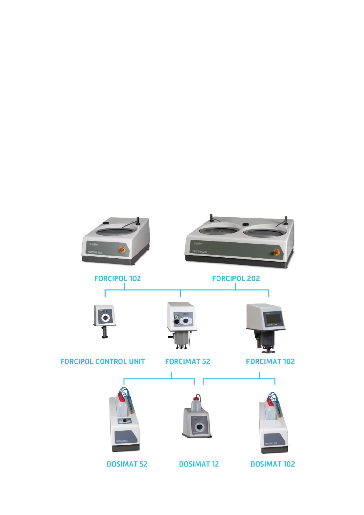
Assembling FORCIMAT 52/102 Automatic Head
FORCIPOL instruments are designed to modular configuration
for manual, semi-automatic and programmable automatic
equipment. When only manual preparation is required,
FORCIPOL Control Unit can be fitted on the FORCIPOL.
FORCIPOL Control Unit
When the number of specimens to be prepared increases,
FORCIPOL instruments can be fitted with one of FORCIMAT
automatic heads (FORCIMAT 52 or FORCIMAT 102) for
automation. FORCIMAT automatic heads provide high rate
sample preparation and frees the operator from the grinding
and polishing procedures.
FORCIMAT series of Automatic Heads are available as two
types: FORCIMAT 52 and FORCIMAT 102.
FORCIMAT 52 provides single force semi automatic
application. It has touch pad controls with turn knob.
FORCIMAT 102 provides single force and central force
application. It has programmable 7” HMI touch screen.
FORCIMAT 52 FORCIMAT 102
CAUTION
Follow approved procedures and take all
necessary preventive safety measures when
lifting and installing this equipment. Improper
lifting can result equipment damage.
Both FORCIPOL Control Unit, FORCIMAT 52 and FORCIMAT
102 are mounted on FORCIPOL base same way. Follow below
steps to step by step mount:
Please be sure that the platform is large enough and can
stand its weight.
You can see the total dimensions and total weight of
FORCIPOL 102/202 together with FORCIMAT 52/102 as
below:
FORCIPOL 102 + FORCIMAT 52/102
Dimensions
W
D
H
45 cm
74 cm
54 cm
Weight
Approx. 66 kgs
FORCIPOL 202 + FORCIMAT 52/102
Dimensions
W
D
H
87 cm
74 cm
54 cm
Weight
Approx. 71 kgs
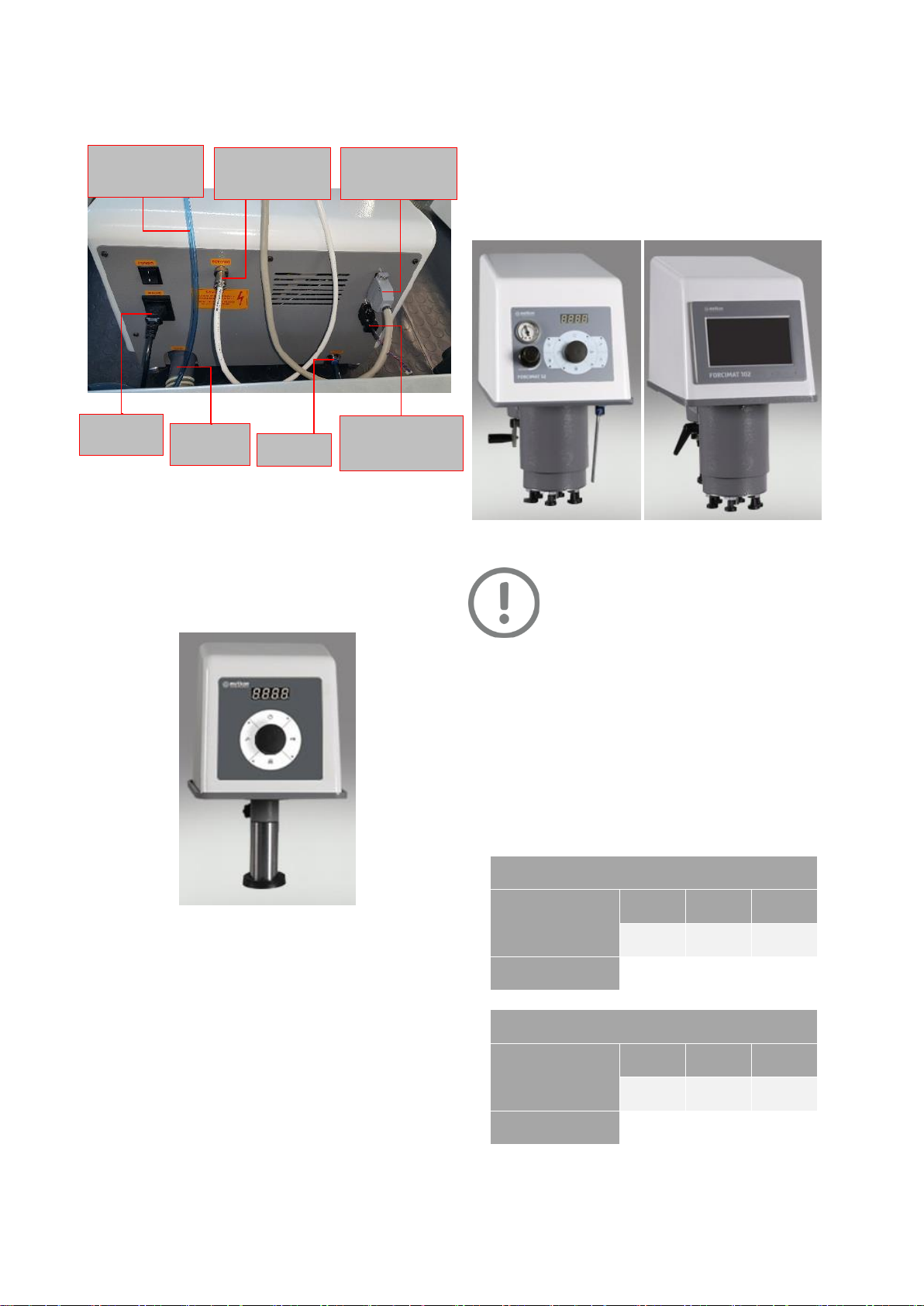
Air Source
Connection to
FORCIMAT 52/102
Drain Water
Outlet
Water Inlet
Power Cable for
Head Unit
Communication
Cable for Head Unit
Communication and
Power Cable for
Dosing Unit
Mains Power
Cable
13
Pull off the plastic plug on the surface of FORCIPOL.
Place FORCIMAT with its column in the FORCIPOL and fix
it from the bottom with the M8 screw. Be sure that the
screw is tighten correctly. (FORCIPOL Control Unit is also
mounted in same way)
Fixing FORCIMAT with M8 Screw at the bottom of FORCIPOL
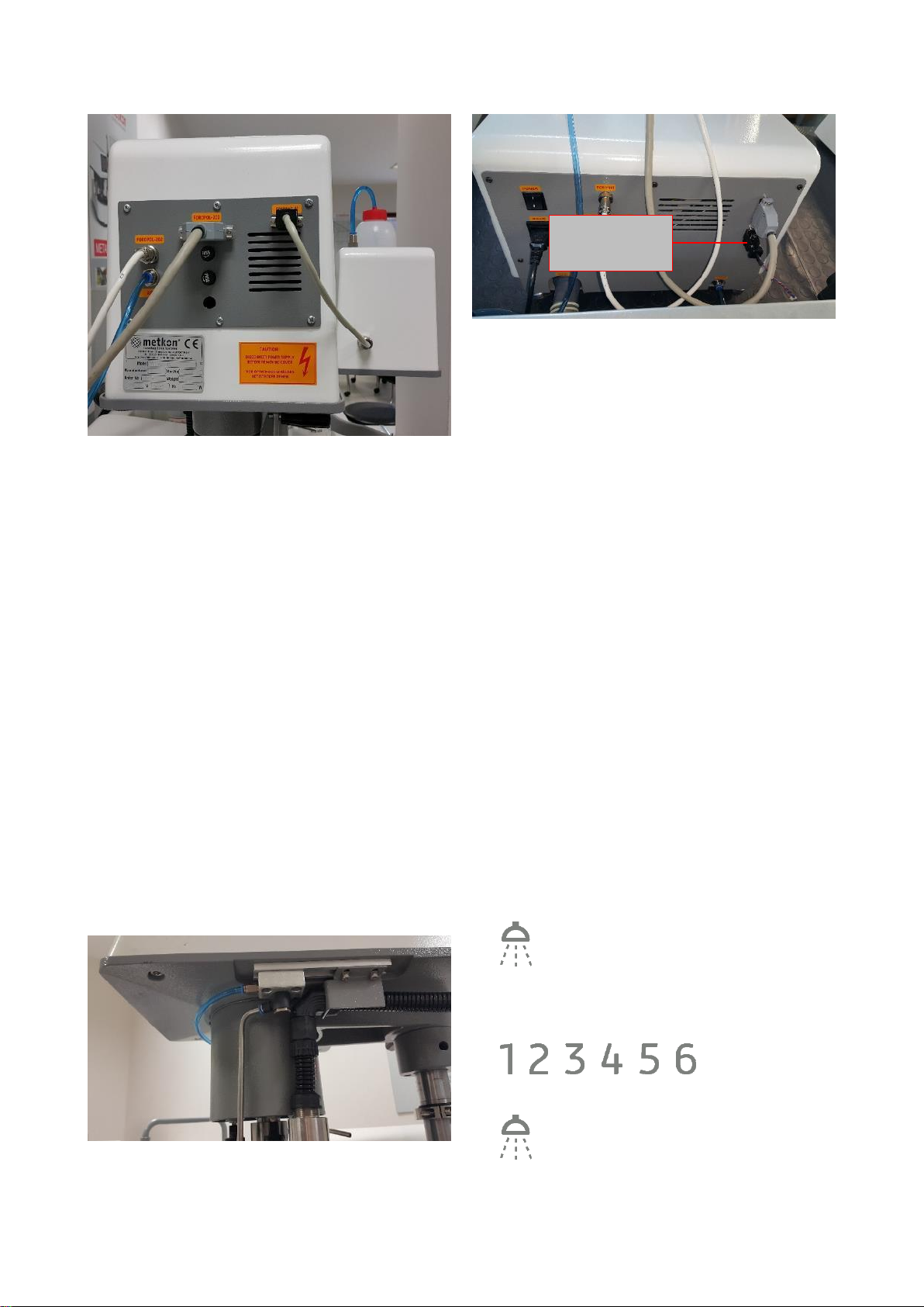
Make power and communication cable connections as
below: (Same for FORCIPOL Control Unit)
FORCIMAT 52/102 Connections
FORCIPOL 102/202 Connections
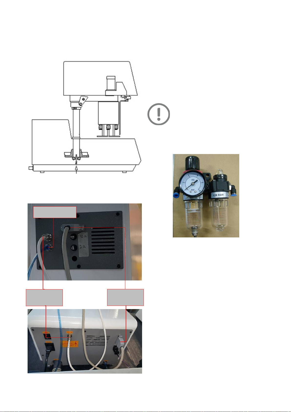
Air Connection
If FORCIPOL 102/202 is equipped with one of FORCIMAT
52/102 automatic head, it requires air supply with 6 bars
pressure. (FORCIPOL Control Unit does not require air
connection)
A compressor, which can generate more than 6 bars and
has 50 liters capacity, is enough for only one equipment.
If you have more equipment that use air supply, please
consult your local compressor dealer to choose correct
compressor.
ATTENTION
If there is a doubt about the quality of the air
supply, make certain that a filter and regulator
unit for compressed air, which is connected in
the airline before FORCIMAT 52/102.
METKON can supply GR 0440 Air Filtering and
Lubricating Unit, which regulates air pressure to 6 bars.
Air Filtering and Lubricating Unit
A pneumatic air hose with 8 mm outer diameter will be
supplied with the equipment. (See: Installation Kit)
Please be sure that you have suitable connection fittings
to connect hose to the airline.
Power Cable for
FORCIMAT 52/102
Communication
Cable for
FORCIMAT 52/102
Air Source Connection
to FORCIMAT 52/102
14
Assembling Sample Holders
The FORCIMAT 52 is designed for only Single Force
applications; the FORCIMAT 102 is designed for both Single
Force and Central Force applications. Six Single Force pistons
prepare one to six samples at the same time. The piston feet
are engineered to provide optimally flat sample preparation.
Use Central Force for multiple simultaneous sample
preparation. A soft start and soft stop motor function helps
prevent sample damage. The mechanical vertical drive
provides downforce without the need for compressed air in
Central Force operation.
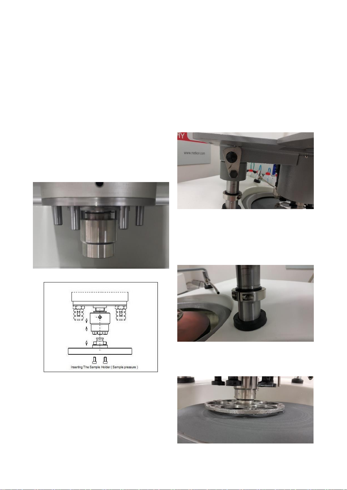
Single and central sample holders are mounted in same way.
Insert the “central or individual force sample holder
adapter”on the automatic head.
Move the chuck upwards by hand.
Insert the sample holder and release the chuck.
Connection Chuck
Mounting Specimen Holder
Adjusting the Height of FORCIMAT 52/102 Head
When you place the FORCIMAT on the FORCIPOL we strongly
advise you to check the distance between the single force
sample holder and the disc when the sample holder is at the
bottom position. It should be 5 mm. If it is longer or shorter
you need to adjust the height. Height of FORCIMAT 52 and
FORCIMAT 102 are adjusted similarly but there is a little
difference.
Follow below steps to adjust height of FORCIMAT 52:
Move the head position handle up. The FORCIMAT 52 will
go up by pneumatic force.
Head Position Handle
Loosen the setscrew of the adjusting collar. If the lenght
you measured at the beginning is shorter than 5 mm,
move the collar upwards and tighten the setscrew again.
If it was longer than 5 mm at the beginning, than you
have to move the collar downwards and tighten
setscrew.
Adjusting Collar
After that check the distance again when the sample
holder is at the bottom position. If the distance is not OK
again you have to do the steps one more time.
Distance Between Sample Holder and Disc Should be 5 mm

15
Follow below steps to adjust height of FORCIMAT 102:
FORCIMAT 102 cannot go up by pneumatic force like
FORCIMAT 52. For this reason, there are two collars to
prevent head from falling down. Do not loosen both of
them at the same time.
If the lenght you measured at the beginning is shorter
than 5 mm, you should move the collar upwards. To do
this;
oLoosen the upper collar.
oLift the head up by the help of another person.
oMove the collar up and tighten.
oLoosen and move up another collar and tighten it.
If it was longer than 5 mm at the beginning, than you
have to move the collars downwards. To do this;
oLoosen the bottom collar.
oMove the collars down and tighten it.
oLoosen another collar and move it down, then
tighten it.
Head Position Handle and Collars
Fixing and Releasing the Automatic Head
Before starting grinding & polishing operation, the automatic
head should be fixed. Both FORCIMAT 52 and FORCIMAT 102
is fixed similar way with head positioning handle.
FORCIMAT 52:
If you turn the handle up, the head will go up by pneumatic
force and will be able to move right and left. You can easily
replace sample holder or disc at this position.
If you turn the handle down, the head will go down. If you
keep it turning more, the head will be fixed and cannot be
moved right and left.
Loose Position Fixing Position
FORCIMAT 102:
If you turn the handle up, the head will be loosen. You can
easily position the head.
If you turn the handle down, the head will be fixed and
cannot be moved right and left.
Loose Position Fixing Position
ATTENTION
Before moving down the automatic head, make
sure that the water tube is not under the
sample holder. Otherwise, the sample holder
may put pressure on the water tube and may
damage it. The damages caused by operator mistake are out
of warranty.

16
LEVOMAT Specimen Loading Fixture
All specimens on the central sample holder should be at the
same level to obtain same result for all samples. Therefore,
you should adjust level of samples before the operation.
LEVOMAT Specimen Loading Fixture is designed for this
purpose as an optional accessory. You adjust the level of the
entire specimen very quickly and easily.
Please see below step by step how to fix samples at the same
level using LEVOMAT:
Put the Specimen Loading Plate on the LEVOMAT.
Diameter of Specimen Loading Plate should be chosen
according to sample holder's diameter.
Place Central Sample Holder on to the Specimen Loading
Plate.
Push the arm downwards to fix sample holder properly.
Place your specimens into the Sample Holder.
Tight each the screws properly using an Allen key.
Pull it upwards to release sample holder. The Sample
Holder is Ready to use with DIGIPREP

17
DOSIMAT Peristaltic Fluid Dispenser
DOSIMAT Peristaltic Dispenser is an optional accessory for the
FORCIMAT 52 and FORCIMAT 102 systems. It is an automatic
fluid dispensing instrument used in combination to obtain
consistent specimens and to save time and consumables.
DOSIMAT can feed both diamond suspensions / lubricants and
aluminium oxide suspensions. Automatic dosing of
consumables is applied precisely for perfect sample surfaces.
Efficiency is further increased with high quality peristaltic
pumps that guarantee exactly the same dosing every time for
automation and control of consumable consumption. The
liquid is dosed exactly to where the operator wants it on the
polishing cloth. No vaporization or spray mist occurs.
It is possible to clean all the tubes with a single button at the
end of preparation steps to eliminate the risk of clogged
tubes.
Three different DOSIMAT Peristaltic Fluid Dispensers are
available for FORCIMAT 52 and FORCIMAT 102:
DOSIMAT 12 (With 1 Peristaltic Pump)
DOSIMAT 12 has one peristaltic and non-misting pump for
diamond suspensions, alumina suspensions, lubricant or 2 in
1 suspensions and can be matched with Forcimat 52 and
Forcimat 102 Automatic Heads. Modern touch pad controls
with ergonomic turn knob allows fast and easy setting of
dispensing parameters like; frequency, dosing time, etc.
parameters and increases productivity. The last parameter
settings are always retained in the memory.
DOSIMAT 52 (With 6 Peristaltic Pump)
DOSIMAT 52 has 5 peristaltic pumps for diamond suspensions
/ lubricant and 1 pump for aluminium oxide suspension or 2
in 1 suspensions and can be matched with Forcimat 52
Automatic Head. Modern touch pad controls with ergonomic
turn knob allows fast and easy setting of dispensing
parameters like; frequency, dosing time, etc. parameters and
increases productivity. The last parameter settings are always
retained in the memory.
DOSIMAT 102 (With 6 Peristaltic Pump)
DOSIMAT 102 has 5 peristaltic pumps for diamond
suspensions / lubricant and 1 pump for aluminium oxide
suspension or 2 in 1 suspensions and can be matched with
Forcimat 102 Automatic Head. Dispensing parameters like;
frequency, dosing time, fluid selection etc. are controlled
through the LCD screen of the FORCIMAT 102 Automatic Head
and can be stored in memory.
DOSIMAT 12/52/102
DOSIMAT bottles are named with numbers on FORCIMAT
102’s software from 1 to 6.
Number 1 bottle has dedicated for alumina suspensions. Do
not put alumina suspensions on the other bottles. These
pumps cannot drip suspension due to density of alumina
suspension. Moreover, they can be clogged up quickly.
Installation of DOSIMAT 12/52/102
DOSIMAT 12
DOSIMAT 12 can be used together with FORCIMAT 52 or
FORCIMAT 102. Follow below steps to install DOSIMAT 12:
Place the mounting bracket of DOSIMAT 12 to the left
hand side of FORCIMAT’s base.
Tighten the screws and fix it properly.
Mount the dosing pipe to the right hand side of
FORCIMAT.
18
Make cable connection.
Activate the DOSIMAT 12 from the FORCIMAT 52 or
FORCIMAT 102.
If you have FORCIMAT 52; follow below steps to activate
DOSIMAT 12:
oKeep pressing the turn-knob until it enter
factors settings menu.
oChoose “P3” by turning the turn-knob, then
press on turn-knob.
oChoose “1” and press turn-knob again. (0: None,
1: DOSIMAT 12, 2: DOSIMAT 52, 3: Both)
oPress disc speed button to exit.
If you have FORCIMAT 102; follow below steps to activate
DOSIMAT 12:
oEnter the SETTINGS >>> METKON SERVICE
menu.
oSet DOSIMAT 12 to “ACTIVATE”
oExit
DOSIMAT 52
DOSIMAT 52 can be used together with FORCIMAT 52. Follow
below steps to install DOSIMAT 52:
Place the DOSIMAT 52 to right or left hand side of
FORCIPOL.
Mount the dosing pipe to the right hand side of
FORCIMAT 52.
Make cable connection.
Activate the DOSIMAT 52 from the FORCIMAT 52.
Follow below steps to activate DOSIMAT 52:
oKeep pressing the turn-knob until it enter
factors setting menu.
oChoose “P3” by turning the turn-knob, then
press on turn-knob.
oChoose “2” and press turn-knob again.
(0: None, 1: DOSIMAT 12, 2: DOSIMAT 52,
3: Both)
oPress disc speed button to exit.
DOSIMAT 102
DOSIMAT 102 can be used together with FORCIMAT 102.
Installation of DOSIMAT 102 is same as DOSIMAT 52. The only
difference is activation. Follow below steps to activate
DOSIMAT 102:
oEnter the SETTINGS >>> METKON SERVICE
menu.
oSet DOSIMAT 102 to “6”
oExit
To Make DOSIMAT Ready for Operation
Fluids are conveyed from bottles to polishing cloth via plastic
hoses. So, the pumps should be run until fluids drip from steel
pipes before the first operation.
Follow below steps to run the pumps:
DOSIMAT 12
Keep pressing the purge button until fluid starts dripping
from the steel pipe.
DOSIMAT 52
Press the number of bottles that you want to use during
operation.
Keep pressing the purge button until fluids start dripping
from the steel pipes.
Communication and
Power Cable for
DOSIMAT 52/102
19
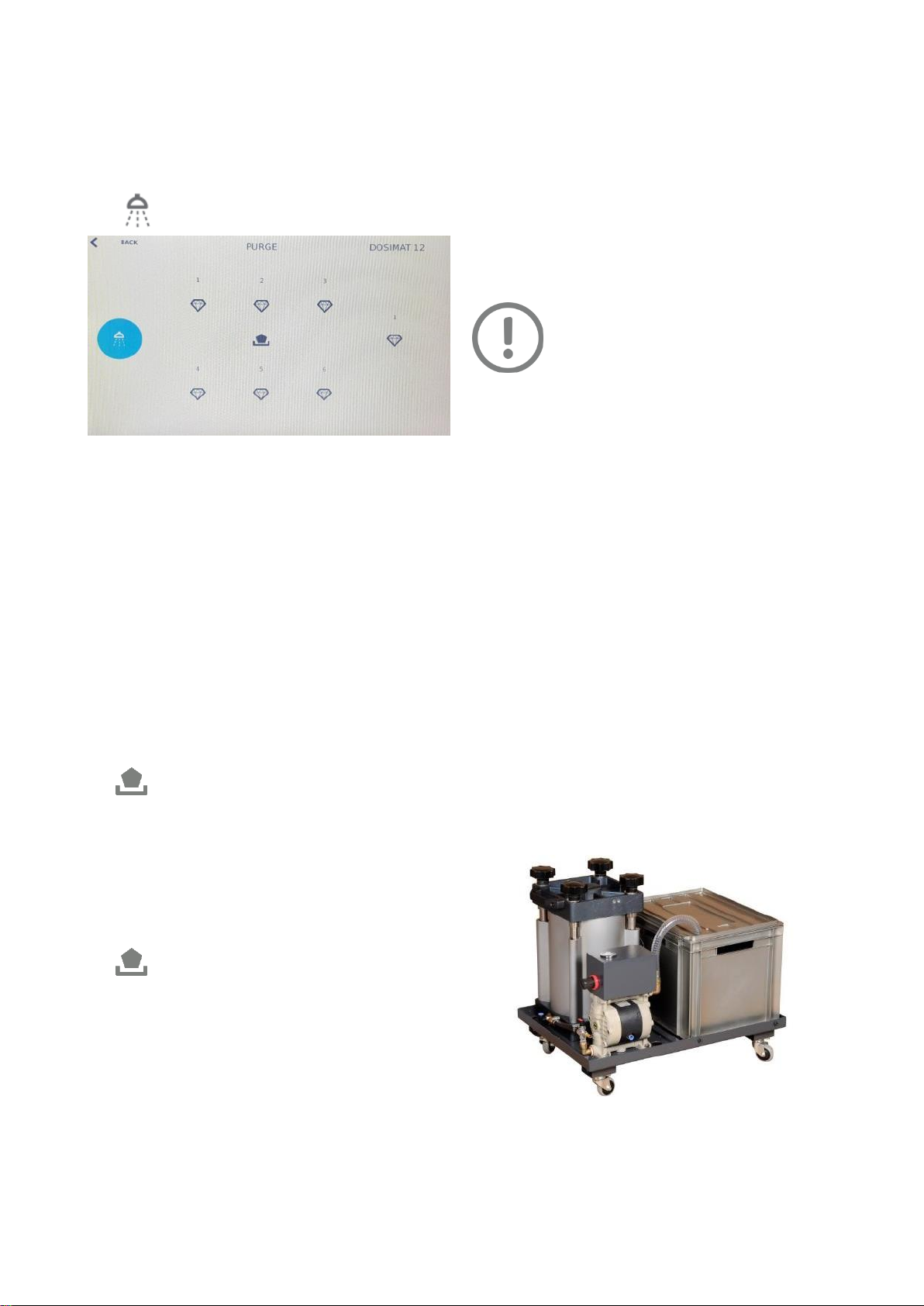
DOSIMAT 102
Enter Manual, Single or Central Operation menu from the
FORCIMAT 102.
Press manual DOSIMAT button from operation menu.
DOSIMAT menu will appear.
Manual DOSIMAT Menu
Activate the pump by pressing bottle icon that you want
to use during polishing operation.
Deactivate the pump by pressing same bottle icon when
it starts to drip.
Cleaning DOSIMAT Hoses
If you do not use the equipment for long time (such as end of
working shift), you should clean the tubes of dosing unit by
using “Retract” function. Otherwise, the tubes can be clogged
and dosing hoses may blow up. Warranty does not cover this
kind of damages. Follow below steps to clean the hoses:
DOSIMAT 12/52
Keep pressing “Retract” button until all fluids come back
to bottles.
DOSIMAT 102
Enter Manual, Single or Central Operation menu from the
FORCIMAT 102.
Press manual DOSIMAT button from operation menu.
DOSIMAT menu will appear.
Keep pressing “Retract” button until all fluids come back
to bottles.
Platen Installation
Align the holes under the platen (polishing wheel) with
the pins on the faceplate.
Place the platen on the base plate with the pins inserted
in the platen.
Press down on the platen to produce a secure fit and
check that the platen does not wobble.
Position and install the splash ring.
ATTENTION
Always use the splash ring to prevent a messy
over-spray. Before use, make sure the platen
surface is clean and free of residue from
previous operations. Adhesive residues may
be removed with an approved solvent.
Using Different Diameter Discs
Both FORCIPOL 102 and FORCIPOL 202 are suitable for Ø200,
Ø230, Ø250 and Ø300 mm working wheels.
For switching between Ø250 and Ø300 mm discs, you
only need to change PVC or Aluminum wheels.
For switching Ø200 mm, you need to change the base
plate (faceplate) first. Then, you can use Ø200 mm PVC
or aluminum wheels.
Please see the order codes and suitable wheel diameters of
base plates:
YM 6505: Base plate for Ø250 mm and Ø300 mm wheels.
YM 0269: Base plate for Ø200 mm and Ø230 mm wheels.
If you need one of these base plates in the future, please
contact with Metkon to order it.
Optional Recirculating Cooling System (ENVIRO)
Enviro Filter Unit is a closed loop recirculating filter system,
which is optionally available. It has a 20-lt reservoir capacity
with 1-micron filter entering the grinder / polisher intake.
Enviro can also be coupled with line water and 80-micron
filtering system for disposal.
ENVIRO Filter Unit
Noise Level
Approx. 60 dB is measured at idle running at a distance of 1 m
from the machine.

20
CONTROL PANEL (FORCIPOL
Control Unit)
FORCIPOL Control Unit has a modern looking and easy to use
operator panel with buttons and knob. It has specially
designed to increase operator comfort and maximize
productivity. All grinding and polishing parameters can be set
easily and quickly. A multipurpose digital display allows you to
observe all parameters.
FORCIPOL Control Unit
Control Button Functions
Time
Disc Speed
Water
Start/Stop
CONTROL PANEL (FORCIMAT 52)
FORCIMAT 52 has a modern looking and easy to use operator
panel with buttons and knob. It has specially designed to
increase operator comfort and maximize productivity. All
grinding and polishing parameters can be set easily and
quickly. A multipurpose digital display allows you to observe
all parameters.
FORCIMAT 52 Control Panel
Control Button Functions
Head Speed
Disc Speed
Time
Opposite Direction
Manual Operation
Water
Pistons Up/Down
Start/Stop
Other manuals for FORCIPOL Series
1
This manual suits for next models
2
Table of contents
Other Metkon Laboratory Equipment manuals


Popular Laboratory Equipment manuals by other brands


Daihan Scientific
Daihan Scientific MSH-20D user manual

ThermoFisher Scientific
ThermoFisher Scientific ARL EQUINOX Series Instruction Notice

Phcbi
Phcbi MCO-170MP operating instructions

NoiseKen
NoiseKen EPS-02Hv2 instruction manual

Hettich
Hettich ROTO SILENTA 630 RS operating instructions

Tencor
Tencor AlphaStep 200 manual


