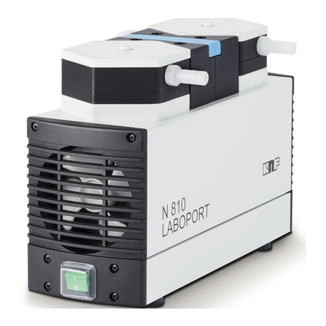
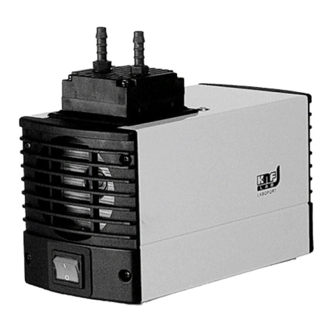
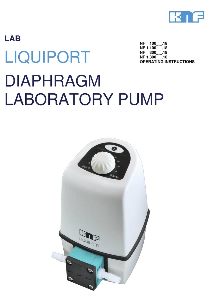
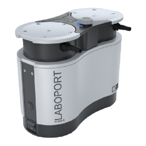
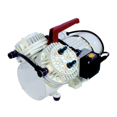
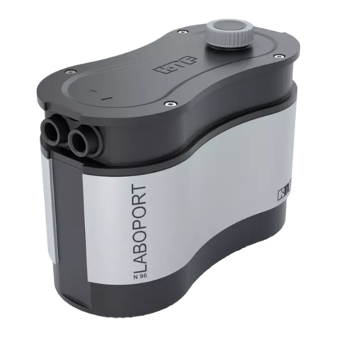
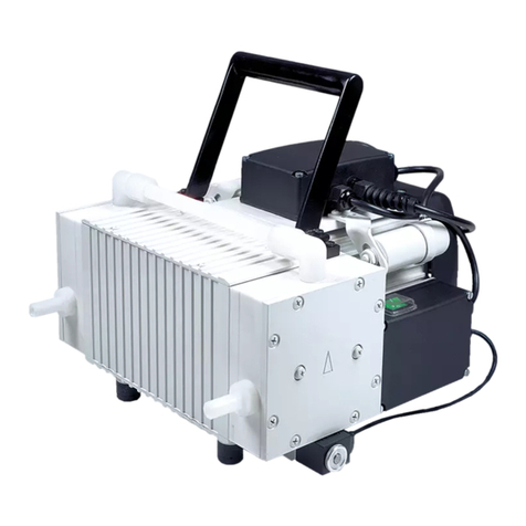
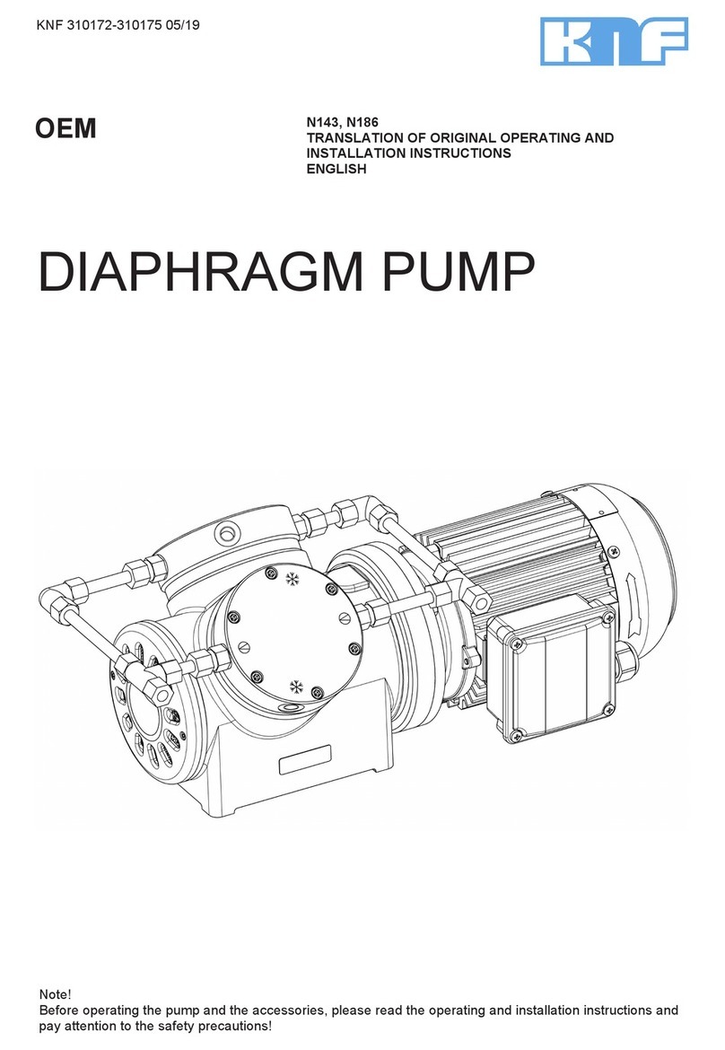
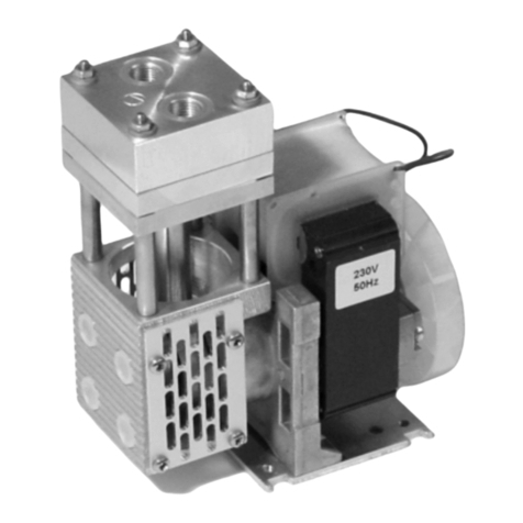
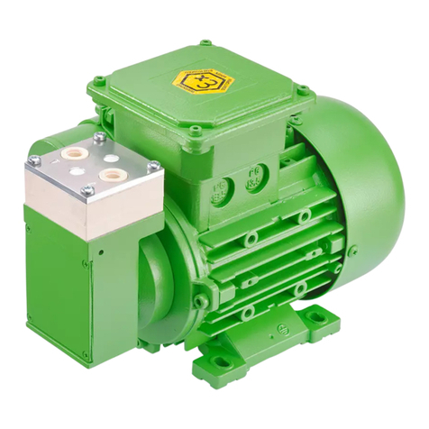
KNF Laboport N820 User manual

KNF 121722-121728 02/10
Translation of original Operating Instructions, english
LABOPORT®
Chemically-resistant Laboratory Pumps
with Modular
A
ccesso
r
ies
Operating Instructions
for Laboratory Pumps N810, N820, N840, N842
and for LABOPORT Systems SR..., SH…, SC…, SCC…
Operating Instructions
Vacuum-Controller NC800 / NBC800

KNF Neuberger UK Ltd
Ave 2, Station Lane Ind Est,
Witney, Oxfordshire,
OX28 4FA, UK
Tel: +44 (0) 1993 778373
Fax: +44 (0)1993 775148
E-Mail: info@knf.co.uk
www.knf.co.uk

LABOPORT Pumps and Systems Content
Translation of original Operating Instructions, english, KNF 121211-121345 01/10 3
Content Page
1. About this document 4
1.1. Using the Operating Instructions 4
1.2. Symbols and Markings 4
2. Use 5
2.1. Proper Use 5
2.2. Improper Use 5
3. Safety 6
4. System overview 8
5. Technical Data 10
5.1. Pumps 10
5.2. Electrical Supply Unit 17
5.3. Vacuum Controller 17
5.4. Vacuum Systems 18
6. Design and Function 19
6.1. Pump 19
6.2. Separator 20
6.3. High Performance Condenser 21
6.4. Vacuum Controller 22
7. Installation, mounting and
connection 23
7.1. Connect pump 23
7.2. Baseplate 24
7.3. Separator 24
7.4. High Performance Condenser 25
7.5. Electrical Supply Unit and
Vacuum Controller 25
7.6. Gas Ballast 28
7.7. Mounting of Systems 28
7.7.1. System SR 28
7.7.2. System SH 29
7.7.3. System SC 30
7.7.4. System SCC 31
7.7.5. Retrofitting from System SC to
System SCC 32
8. Operation 33
8.1. Pump 33
8.1.1. Preparing for Start-up 33
8.1.2. Starting 33
8.2. Switching Pump/System on and
off 35
8.3. Notices related to System
Operation 35
8.3.1. Separators 35
8.3.2. High Performance Condenser 35
8.3.3. Vacuum Controller 36
8.3.4. Gas Ballast 36
9. Servicing 37
9.1. Servicing Schedule 37
9.2. Cleaning 37
9.2.1. Flushing Pump 37
9.2.2. Cleaning Pump 37
9.2.3. Emptying and Cleaning the
Separator 37
9.2.4. Emptying and Cleaning the
Condenser 37
9.3. Changing Diaphragm and Valve
Plates/Sealings 38
10. Troubleshooting 42
10.1. Pump/System without Vacuum
Controller 42
10.2. System with one Vacuum
Controller 43
10.3. System with two Vacuum
Controllers 45
10.4. Fault cannot be rectified 45
11. Ordering Information 46
11.1. Pumps and Spare Parts 46
11.2. Accessories for Pump Systems 46
12. Decontamination Declaration 47

About this document LABOPORT Pumps and Systems
4 Translation of original Operating Instructions, english, KNF 121211-121345 01/10
1. About this document
1.1. Using the Operating Instructions
The Operating Instructions are part of the pump/system.
Carefully study the Operating Instructions before using a pump
or system.
Always keep the Operating Instructions handy in the work
area.
Pass on the Operating Instructions to the next owner.
Customer-specific project systems or pumps (systems and pump
models which begin with “PJ” or “PM”) may differ from the Operat-
ing Instructions.
For project systems and pumps, also observe the agreed upon
specifications.
1.2. Symbols and Markings
Warning
WARNING
A danger warning is located here.
Possible consequences of a failure to observe the
warning are specified here. The signal word, e.g.
Warning, indicates the danger level.
Measures for avoiding the danger and its conse-
quences are specified here.
Danger levels
Signal word Meaning Consequences if not observed
DANGER warns of immedi-
ate danger
Death or serious injuries
and/or serious damage are the
consequence.
WARNING warns of possible
danger
Death or serious injuries
and/or serious damage are
possible.
CAUTION warns of a possibly
dangerous situa-
tion
Minor injuries or damage are
possible.
Tab. 1
Other information and symbols
An activity to be carried out (a step) is specified here.
1. The first step of an activity to be carried out is specified here.
Additional, consecutively numbered steps follow.
This symbol refers to important information.
Project systems and pumps

LABOPORT Pumps and Systems Use
Translation of original Operating Instructions, english, KNF 121211-121345 01/10 5
2. Use
2.1. Proper Use
The pump/system is exclusively intended for transferring gases
and vapors.
Owner's responsibility
Only install and operate the pump/system under the operating
parameters and conditions described in chapter 5, Technical data.
Make sure that the installation location is dry and the pump/system
is protected against rain, splash, hose and drip water.
Before using a medium, check the compatibility of the materials of
the pump head, diaphragm and valves with the medium.
Before using a medium, check whether the medium can be trans-
ferred danger-free in the specific application case.
Only transfer gases which remain stable under the pressures and
temperatures occurring in the pump.
The high performance condenser must be installed on the outlet
side of the pump; if it is installed on the inlet side there is a danger
of implosion.
Observe the correct usage of the gas- and cooling liquid-
connections on the high performance condenser. Inlet and outlet
connections for the gas are not interchangeable.
Laboratory equipment or additional components connected to a
pump/system have to be suitable for use with the pneumatic capa-
bilities of the pump (see chapter 5.1, page 10).
2.2. Improper Use
The pump/system may not be operated in an explosive atmos-
phere.
The pump/system is not suitable for transferring dusts.
The pump/system is not suitable for transferring liquids.
For LABOPORT systems with vacuum controller: The vacuum
system must not be used if the entry of air or gas into the vacuum
system during venting (pump vent valve) could result in the crea-
tion of reactive, explosive or otherwise hazardous mixtures (e.g.
with the medium).
The pump/the system must not be used to create vacuum and
overpressure simultaneously.
An overpressure must not be applied to the suction side of the
pump/ the system.
Operating parameters and
conditions
Requirements for
transferred medium
High performance condenser
Accessories

Safety LABOPORT Pumps and Systems
6 Translation of original Operating Instructions, english, KNF 121211-121345 01/10
3. Safety
Note the safety precautions in chapters 7. Installation, mount-
ing and connection, and 8. Operation.
The pump/system is built according to the generally recognized
rules of technology and in accordance with the occupational safety
and accident prevention regulations. Nevertheless, dangers can
result during their use which lead to injuries to the user or others,
or to damage to the pump/system or other property.
Only use the pump/system when it is in a good technical and
proper working order, in accordance with its intended use, observ-
ing the safety advice within the operating instructions, at all times.
Make sure that only trained and instructed personnel or specially
trained personnel work on the pump/system. This especially ap-
plies to assembly, connection and servicing work.
Make sure that the personnel has read and understood the operat-
ing instructions, and in particular the "Safety" chapter.
Observe the accident prevention and safety regulations when
performing any work on the pump/system and during operation.
Do not expose any part of your body to the vacuum.
Open housing parts with notice sticker (see fig. 1) only after
separating mains plug from power source.
When transferring dangerous media, observe the safety regula-
tions when handling these media.
Be aware that the pump/system is not designed to be explosion-
proof.
Make sure the temperature of the medium is always sufficiently
below the ignition temperature of the medium, to avoid ignition or
explosion. This also applies for unusual operational situations.
Note that the temperature of the medium increases when the pump
compresses the medium.
Hence, make sure the temperature of the medium is sufficiently
below the ignition temperature of the medium, even when it is
compressed to the maximum permissible operating pressure of the
pump. The maximum permissible operating pressure of the pump
is stated in the technical specifications (see chapter 5.1, page 10).
If necessary, consider any external sources of energy, such as
radiation, that may add heat to the medium.
In case of doubt, consult the KNF customer service.
Store all replacement parts in a protected manner and dispose of
them properly in accordance with the applicable environmental
protection regulations. Observe the respective national and inter-
national regulations. This especially applies to parts contaminated
with toxic substances.
Personnel
Working in a safety-
conscious manner
Fig. 1: Notice sticker
Handling dangerous media
Handling flammable media
Environmental protection

LABOPORT Pumps and Systems Safety
Translation of original Operating Instructions, english, KNF 121211-121345 01/10 7
The KNF LABOPORT®pumps conform to the safety regulations of
the EC Directive 2004/108/EC concerning Electromagnetic Com-
patibility and the EC Directive 2006/42/EC concerning Machinery.
The requirements of the following harmonised standards are
fulfilled:
DIN EN 61010-1
DIN EN 61326-1
DIN EN 61000-3-2/3
The pumps correspond to IEC 664:
the overvoltage category II
the pollution degree 2
Only have repairs to the pump/system carried out by the KNF
Customer Service responsible.
Only authorized personnel should open those parts of the housing
that contain live electrical parts.
Use only genuine parts from KNF for servicing work.
Standards
Customer service and
repairs

System overview LABOPORT Pumps and Systems
8 Translation of original Operating Instructions, english, KNF 121211-121345 01/10
4. System overview
1Electrical supply unit
2 Vacuum controller
3 Vent valve at vacuum
controller
4 On/off switch of vacuum
controller
5 Pump vent valve
6 Vacuum valve
7High performance con-
denser
8Hose connector
9 Angled nozzle for coolant
10 Spring clamp
11 Flask for condenser
12 Support for high perform-
ance condenser
13 Locating pin for pump
14 Separator
15 Holder for Separator
16 Support for vacuum control-
ler
17 Baseplate
18 Vacuum pump
19 On/off switch of pump
Fig. 2: Full expanded LABOPORT System SCC..., for example pump
model N 840.3 FT.18 (symbolic)

LABOPORT Pumps and Systems System overview
Translation of original Operating Instructions, english, KNF 121211-121345 01/10 9
Fig. 3: LABOPORT Systems
System
Module SR... SH... SC... SCC...
Pump X X X X
Baseplate X X X X
2 separators X
1 separator X X X
High performance
condenser
X X X
Electrical supply unit X X
1 vacuum controller X
2 vacuum controllers X
Tab. 2
Each pump and all systems can be expanded modularly up to
a full system SCC… (see chapter 7.7, page 28).

Technical Data LABOPORT Pumps and Systems
10 Translation of original Operating Instructions, english, KNF 121211-121345 01/10
5. Technical Data
5.1. Pumps
All pumps are secured against overheating with thermal
switches and are equipped with a mains fuse.
Pump materials (for all pump types) *
Pump head PTFE
Diaphragm PTFE coated
Valve FFPM
Tab. 3 *according to DIN ISO 1629 and 1043.1
Refer to the type plate for the pump’s electrical configuration.
N 810 FT.18
Pneumatic performance
Max. permissible operating
pressure [bar g]
1.0
Ultimate vacuum [mbar abs.] ≤100
Delivery rate at atm. pressure
[l/min]*
max. 10
Pneumatic connection
Hose connection [mm] ID 10
Ambient and media temperature
Permissible
ambient temperature
+ 5 °C to + 40 °C
Permissible media temperatu-
re
+ 5 °C to + 40 °C
Other parameters
Weight [kg] 5.9
Dimensions: L x H x W [mm] 256 x 187 x 146
Maximum permissible ambient
relative humidity
80 % for temperatures up to
31 °C, decreasing linearly to
50 % at 40 °C
Maximum altitude of site
[m above sea level]
2000
Electrical Data
Voltage [V] 100 115 230
Frequency [Hz] 50/60 60 50
Maximum current consump-
tion [A]
1.4 1.3 0.6
Power consumption pump [W] 110 110 100
Maximum permitted mains
voltage fluctuation
+/- 10 % +/- 10 % +/- 10 %
Fuse pump
(2x) T [A]
2.5 2.5 1.25
Protection class motor IP44
Tab. 4 * Liters in standard state (1,013 mbar)

LABOPORT Pumps and Systems Technical Data
Translation of original Operating Instructions, english, KNF 121211-121345 01/10 11
N 820 FT.18
Pneumatic performance
Max. permissible operating
pressure [bar g]
1.0
Ultimate vacuum [mbar abs.] ≤100
Delivery rate at atm. pressure
[l/min]*
max. 20
Pneumatic connection
Hose connection [mm] ID 10
Ambient and media temperature
Permissible
ambient temperature
+ 5 °C to + 40 °C
Permissible media temperatu-
re
+ 5 °C to + 40 °C
Other parameters
Weight [kg] 7.1
Dimensions: L x H x W [mm] 268 x 207 x 159
Maximum permissible ambient
relative humidity
80 % for temperatures up to
31 °C, decreasing linearly to
50 % at 40 °C
Maximum altitude of site
[m above sea level]
2000
Electrical Data
Voltage [V] 100 115 230
Frequency [Hz] 50/60 60 50
Maximum current consump-
tion [A]
2.2 1.9 0.9
Power consumption pump [W] 145 145 130
Maximum permitted mains
voltage fluctuation
+/- 10 % +/- 10 % +/- 10 %
Fuse pump
(2x) T [A]
4.0 3.15 2.0
Protection class motor IP44
Tab. 5 * Liters in standard state (1,013 mbar)

Technical Data LABOPORT Pumps and Systems
12 Translation of original Operating Instructions, english, KNF 121211-121345 01/10
N 840 FT.18
Pneumatic performance
Max. permissible operating
pressure [bar g]
1.0
Ultimate vacuum [mbar abs.] ≤100
Delivery rate at atm. pressure
[l/min]*
max. 34
Pneumatic connection
Hose connection [mm] ID 10
Ambient and media temperature
Permissible
ambient temperature
+ 5 °C to + 40 °C
Permissible media temperatu-
re
+ 5 °C to + 40 °C
Other parameters
Weight [kg] 10.3
Dimensions: L x H x W [mm] 297x 226 x 171
Maximum permissible ambient
relative humidity
80 % for temperatures up to
31 °C, decreasing linearly to
50 % at 40 °C
Maximum altitude of site
[m above sea level]
2000
Electrical Data
Voltage [V] 100 115 230
Frequency [Hz] 50/60 60 50
Maximum current consump-
tion [A]
4.4 3.2 1.5
Power consumption pump [W] 200 220 180
Maximum permitted mains
voltage fluctuation
+/- 10 % +/- 10 % +/- 10 %
Fuse pump
(2x) T [A]
6.3 6.3 3.15
Protection class motor IP44
Tab. 6 * Liters in standard state (1,013 mbar)N 810.3 FT.18

LABOPORT Pumps and Systems Technical Data
Translation of original Operating Instructions, english, KNF 121211-121345 01/10 13
N 810.3 FT.18
Pneumatic performance
Max. permissible operating
pressure [bar g]
1.0
Ultimate vacuum [mbar abs.] ≤8
Delivery rate at atm. pressure
[l/min]*
max. 10
Pneumatic connection
Hose connection [mm] ID 10
Ambient and media temperature
Permissible
ambient temperature
+ 5 °C to + 40 °C
Permissible media temperatu-
re
+ 5 °C to + 40 °C
Other parameters
Weight [kg] 6.9
Dimensions: L x H x W [mm] 281 x 187 x140
Maximum permissible ambient
relative humidity
80 % for temperatures up to
31 °C, decreasing linearly to
50 % at 40 °C
Maximum altitude of site
[m above sea level]
2000
Electrical Data
Voltage [V] 100 115 230
Frequency [Hz] 50/60 60 50
Maximum current consump-
tion [A]
1.4 1.3 0.6
Power consumption pump [W] 100 110 90
Maximum permitted mains
voltage fluctuation
+/- 10 % +/- 10 % +/- 10 %
Fuse pump
(2x) T [A]
2.5 2.5 1.25
Protection class motor IP44
Tab. 7 *Liters in standard state (1,013 mbar)

Technical Data LABOPORT Pumps and Systems
14 Translation of original Operating Instructions, english, KNF 121211-121345 01/10
N 820.3 FT.18
Pneumatic performance
Max. permissible operating
pressure [bar g]
1.0
Ultimate vacuum [mbar abs.] ≤8
Delivery rate at atm. pressure
[l/min]*
max. 20
Pneumatic connection
Hose connection [mm] ID 10
Ambient and media temperature
Permissible
ambient temperature
+ 5 °C to + 40 °C
Permissible media temperatu-
re
+ 5 °C to + 40 °C
Other parameters
Weight [kg] 9.3
Dimensions: L x H x W [mm] 312 x 207 x 144
Maximum permissible ambient
relative humidity
80 % for temperatures up to
31 °C, decreasing linearly to
50 % at 40 °C
Maximum altitude of site
[m above sea level]
2000
Electrical Data
Voltage [V] 100 115 230
Frequency [Hz] 50/60 60 50
Maximum current consump-
tion [A]
1.8 1.2 0.7
Power consumption pump [W] 130 130 120
Maximum permitted mains
voltage fluctuation
+/- 10 % +/- 10 % +/- 10 %
Fuse pump
(2x) T [A]
3.15 2.5 1.6
Protection class motor IP44
Tab. 8 *Liters in standard state (1,013 mbar)

LABOPORT Pumps and Systems Technical Data
Translation of original Operating Instructions, english, KNF 121211-121345 01/10 15
N 840.3 FT.18
Pneumatic performance
Max. permissible operating
pressure [bar g]
1.0
Ultimate vacuum [mbar abs.] ≤8
Delivery rate at atm. pressure
[l/min]*
max. 34
Pneumatic connection
Hose connection [mm] ID 10
Ambient and media temperature
Permissible
ambient temperature
+ 5 °C to + 40 °C
Permissible media temperatu-
re
+ 5 °C to + 40 °C
Other parameters
Weight [kg] 12.6
Dimensions: L x H x W [mm] 341 x 226 x 166
Maximum permissible ambient
relative humidity
80 % for temperatures up to
31 °C, decreasing linearly to
50 % at 40 °C
Maximum altitude of site
[m above sea level]
2000
Electrical Data
Voltage [V] 100 115 230
Frequency [Hz] 50/60 60 50
Maximum current consump-
tion [A]
4.4 3.2 1.5
Power consumption pump [W] 220 250 245
Maximum permitted mains
voltage fluctuation
+/- 10 % +/- 10 % +/- 10 %
Fuse pump
(2x) T [A]
6.3 6.3 3.15
Protection class motor IP44
Tab. 9 *Liters in standard state (1,013 mbar)

Technical Data LABOPORT Pumps and Systems
16 Translation of original Operating Instructions, english, KNF 121211-121345 01/10
N 840.1.2 FT.18
Pneumatic performance
Max. permissible operating
pressure [bar g]
1.0
Ultimate vacuum [mbar abs.] ≤90
Delivery rate at atm. pressure
[l/min]*
max. 60
Pneumatic connection
Hose connection [mm] ID 10
Ambient and media temperature
Permissible
ambient temperature
+ 5 °C to + 40 °C
Permissible media temperatu-
re
+ 5 °C to + 40 °C
Other parameters
Weight [kg] 12.6
Dimensions: L x H x W [mm] 341 x 226 x 160
Maximum permissible ambient
relative humidity
80 % for temperatures up to
31 °C, decreasing linearly to
50 % at 40 °C
Maximum altitude of site
[m above sea level]
2000
Electrical Data
Voltage [V] 100 115 230
Frequency [Hz] 50/60 60 50
Maximum current consump-
tion [A]
5.1 4.2 1.9
Power consumption pump [W] 275 280 270
Maximum permitted mains
voltage fluctuation
+/- 10 % +/- 10 % +/- 10 %
Fuse pump
(2x) T [A]
6.3 6.3 3.15
Protection class motor IP44
Tab. 10 *Liters in standard state (1,013 mbar)

LABOPORT Pumps and Systems Technical Data
Translation of original Operating Instructions, english, KNF 121211-121345 01/10 17
N 842.3 FT.18
Pneumatic performance
Max. permissible operating
pressure [bar g]
1.0
Ultimate vacuum [mbar abs.] ≤2
Delivery rate at atm. pressure
[l/min]*
max. 34
Pneumatic connection
Hose connection [mm] ID 10
Ambient and media temperature
Permissible
ambient temperature
+ 5 °C to + 40 °C
Permissible media temperatu-
re
+ 5 °C to + 40 °C
Other parameters
Weight [kg] 13.4
Dimensions: L x H x W [mm] 341 x 223 x 167
Maximum permissible ambient
relative humidity
80 % for temperatures up to
31 °C, decreasing linearly to
50 % at 40 °C
Maximum altitude of site
[m above sea level]
2000
Electrical Data
Voltage [V] 100 115 230
Frequency [Hz] 50/60 60 50
Maximum current consump-
tion [A]
4.4 3.2 1.5
Power consumption pump [W] 260 290 245
Fuse pump
(2x) T [A]
6.3 6.3 3.15
Protection class motor IP44
Tab. 11 *Liters in standard state (1,013 mbar)
5.2. Electrical Supply Unit
Electrical Data
Voltage [V] 100 115 230
Frequency [Hz] 50/60 60 50
Power consumption* [W] 270 300 295
Fuse pump
(2x) T [A]
6.3 6.3 3.15
Tab. 12
* includes the power consumption of the whole system (inclusive pump
and vacuum controller); for pumps N 840.1.2 FT.18 and N 842.3 FT.18
power consumption raises by approx. 50 W.
5.3. Vacuum Controller
See Operating Manual of the vacuum controller.

Technical Data LABOPORT Pumps and Systems
18 Translation of original Operating Instructions, english, KNF 121211-121345 01/10
5.4. Vacuum Systems
Ambient temperature
Permissible
ambient temperature
+ 5 °C to + 40 °C
Operating parameters of coolant (only for high performance condensers)
Permissible pressure [bar g] 3
Permissible temperature - 15 °C to + 20 °C
Condenser connectors For tube 8mm ID
Tab. 13

LABOPORT Pumps and Systems Design and Function
Translation of original Operating Instructions, english, KNF 121211-121345 01/10 19
6. Design and Function
6.1. Pump
Design
1Connection piece
2Pneumatic connection
3Pump head
4Outlet (pressure side)
5Inlet (suction side)
6Power switch
Fig. 4: Diaphragm pump (shown: pump N 840.3 FT.18)
Function Diaphragm pump
1Outlet valve
2Inlet valve
3Transfer chamber
4Diaphragm
5Eccentric
6 Connecting rod
7Pump drive
Fig. 5: Pump head
Diaphragm pumps transfer, compress (depending on pump ver-
sion) and evacuate gases and vapors.
The elastic diaphragm (4) is moved up and down by the eccentric
(5) and the connecting rod (6). In the downward stroke it aspirates
the gas to be transferred via the inlet valve (2). In the upward
stroke, the diaphragm presses the medium out of the pump head
via the outlet valve (1). The transfer chamber (3) is hermetically
separated from the pump drive (7) by the diaphragm.

Design and Function LABOPORT Pumps and Systems
20 Translation of original Operating Instructions, english, KNF 121211-121345 01/10
6.2. Separator
Design
1Tubing
2Hose nozzle
3Separator container
4Holder for separator
1
2
3
4
Fig. 6: Separator (shown: LABOPORT system SR with pump
N 840.3 FT.18 as example)
Function
Condensable components in the gas can be separated on the
pressure side of the pump. On the suction side the separator
collects particular matter and droplets. This protects the pump from
contamination.
The separator is made of a specially treated glass and features
implosion protection.
This manual suits for next models
11
Table of contents
Other KNF Water Pump manuals
Popular Water Pump manuals by other brands

Graco
Graco T2 instructions

CPS-Pumps
CPS-Pumps CST Series Installation, operation & maintenance manual

proril
proril TANK Series instruction manual

Flotec
Flotec MULTIMAX 4 S LOGIC-SAFE Use and maintenance manual

BUSCH
BUSCH COBRA Oxygen NC 0400 B instruction manual

Regulus
Regulus CSE2 MIX-BP F W 1F Installation and operation manual