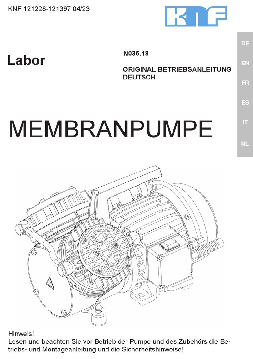
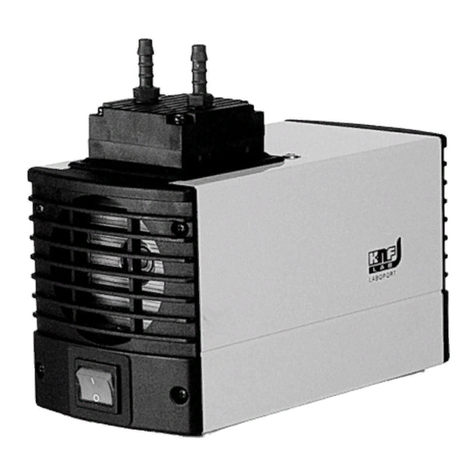
KNF N 012 AT. 16 E Product guide

KNF 121222-121485 08/11
Translation of original Operating and Installation Instructions, english
Operating and Installation Instructions
Diaphragm
Vacuum Pumps
and Compressors
Type range: N 012 AT. 16 E N 024 AT. 16 E N 036 AT. 16 E N 036.0 AT. 16 E
N 012 ST. 11 E N 024 ST. 11 E N 036 ST. 11 E N 036.0 ST. 11 E
N 012 ST. 16 E N 024 ST. 16 E N 036 ST. 16 E N 036.0 ST. 16 E
N 012 ST. 26 E N 024 ST. 26 E N 036 ST. 26 E N 036.0 ST. 26 E
Fig. 1: N 012 ST.26 E
You have selected a high-quality KNF product; the following tips will help you operate it safely, and relia-
bly over a long period of time. Carefully study the Operating and Installation Instructions before using the
pumps and observe at all times the relevant instructions to avoid dangerous situations. The manual was
produced for the serial pumps stated above. With customer-specified projects (pump types starting with
“PJ“ or “PM“) there could be differences in detail. For customer-specified projects please therefore take
into account any agreed technical specifications, as well as these instructions.
List of Contents Page
1. Description, Operating Conditions............................................ 2
2. Safety ....................................................................................... 4
3. Installation ................................................................................ 5
4. Operation.................................................................................. 8
5. Servicing................................................................................. 13
6. Cleaning ................................................................................. 18
7. Trouble Shooting .................................................................... 18
8. Spare parts and accessories.................................................. 21
9. Tables..................................................................................... 22
10. Accessory ............................................................................... 22
11. Decontamination Declaration ................................................. 23
KNF Neuberger GmbH
Alter Weg 3
79112 Freiburg
D-Germany
Phone +49-(0)7664 / 5909-0
Fax +49-(0)7664 / 5909-99
www.knf.de

Description, Operating Conditions Diaphragm Vacuum Pumps N 012, N 024, N 036
2 Translation of original Operating and Installation Instructions, english, KNF 121222-121485 08/11
1. Description, Operating Conditions
KNF pumps in the N 012, N 024, N 036 and N 036.0 range trans-
fer, evacuate and compress 100% oil-free. In operation they are
gas-tight (leak rate: 6 x 10⁻³ mbar x l/sec), and maintenance-free.
Depending on the design, the pumps have the following character-
istics:
.16 designs have temperature-resistant pump heads for
media with temperatures of up to 240 °C.
.11 designs have a heating inset which heats the pump
head to 240 °C (thermostatically regulated).
.26 designs have a heating inset and an electronic control
unit, so that the pump head can be heated to a selected
temperature (60-240 °C). The software provided can be
used to control the pump through a computer and operate
it using userpredefined cycles. The operating data are
saved on the PC and can be printed out as a graphic.
1.1. Electrical Equipment
See the type-plate for full electrical data of the motor.
The motors have IP54 protection class as standard, with IP20 for
the pump heads in the .11 and .26 models.
The motors used are fitted as standard with a thermal switch to
protect against overloading.
1.2. Operating Conditions
Handling air, gases, and vapours at temperatures between
+ 5 °C … + 240 °C.
For maximum permissible operating pressure, ultimate vacuum,
and flow capacity see section 9.
The pumps must not be used in areas where there is a danger of
explosion.
Before pumping a medium, the compatibility of materials of pump
head, diaphragm and valves with the medium must be checked (for
pump materials: see section 9).
These pumps must not be used for liquids. You will find suitable
liquid pumps in our Product Program.
If your potential application lies outside the above limits discuss it
with our technical adviser (see last page for contact telephone
number).

Diaphragm Vacuum Pumps N 012, N 024, N 036 Description, Operating Conditions
Translation of original Operating and Installation Instructions, english, KNF 121222-121485 08/11 3
1.3. Ambient Conditions
When the pump is operating the following ambient conditions must
be maintained:
Ambient temperature during operation: between
+ 10 °C … + 40 °C.
The pump must not be used in areas where there is a
danger of explosion.
During operation an adequate supply of air for cooling
must be provided.
1.4. Pump materials
See section 9.

Safety Diaphragm Vacuum Pumps N 012, N 024, N 036
4 Translation of original Operating and Installation Instructions, english, KNF 121222-121485 08/11
2. Safety
Note that the pumps may only be used for their intended purpose.
The pumps must not be used in areas where there is a danger of
explosion.
Components connected to the pump must be designed to with-
stand the pneumatic performance of the pump.
Take care that safety regulations are observed when connecting
the pump to the electricity supply.
When the operation of the pump is interrupted by the thermal
switch, the pump will re-start automatically after cooling down.
Take all care necessary to prevent this leading to a dangerous
situation.
Specific safety instructions for the media being handled must be
observed.
When using hot media, the pneumatic pump suction and pressure
lines heat up, as do the pump head and the head insulation. Do not
touch these parts; they could burn you.
Use only original KNF spare parts.
For the purposes of the Machinery Directive 2006/42/EC, pumps
are “partly completed machinery,” and are therefore to be regarded
as not ready for use. Partly completed machinery may not be
commissioned until such time as it has been determined that the
machine in which the partly completed machinery is to be
assembled is in conformity with the provisions of the Machinery
Directive 2006/42/EC. The essential requirements of Annex I of
Directive 2006/42/EC (general principles) are applied and
observed.
The pumps conform to the EC Directive 2004/108/EC concerning
Electromagnetic Compatibility.
The following harmonized standards have been used:
DIN EN 61326-1
DIN EN 61000-3-2/3
DIN EN 60204-1
EC Directives / Standards

Diaphragm Vacuum Pumps N 012, N 024, N 036 Installation
Translation of original Operating and Installation Instructions, english, KNF 121222-121485 08/11 5
3. Installation
The pumps are built-in devices intended for installation in
equipment. When installing them make certain that accident
prevention regulations, and safety instructions, including
those for subsequent operation are observed. The safety
instructions in section 2 must be observed.
The dimensions of the mountings are given in Data Sheet.
Install the pump so that the fan can draw in sufficient cooling air.
Fit the pump at the highest point in the system, so that condensate
cannot collect in the head of the pump - that prolongs working life.
DANGER
Extreme danger from electrical shock
Only have the pump connected by an authorized
specialist.
Only have the pump connected when the power
supply is disconnected.
Compare the supply data with the data on the motor-plate. The
voltage must not vary by more than +10% and -10% from that
shown on the type-plate.
In the electrical installation, arrangements (complying with EN
60335-1) must be made for disconnecting the pump motor from the
electrical supply.
The pump must be installed so that contact with live parts (e.g.
electrical connection) is impossible.
We recommend that a fuse is installed in the supply circuit; the
operating current is given in Data Sheet.
Electrical connection
1. Take off the housing for the electronics or terminal cover (see
fig. 2); to do this, release the four screws.
2. Draw the mains cables into the electronics housing or the
terminal cover through the free cable screw holes.
Mechanical
Electrical
Fig. 2: Explanation of important
elements on the basis of example
N 012 ST.26 E
Specification
1Head insolation
2Fixing screws of head
insulation
3Electronic housing (.-26-
design only) or terminal
cover (.-11-and .16-
designs)

Installation Diaphragm Vacuum Pumps N 012, N 024, N 036
6 Translation of original Operating and Installation Instructions, english, KNF 121222-121485 08/11
3. Connect the mains cables to the connections L 1 and N of
the luster terminal (see figs. 3a, 3b or 4).
4. Connect the earth (ground) wire to the pump motor.
5. Place the electronics housing or the terminal cover back in
position and screw it tight; make sure the housing sealing is
properly sited.
6. Only .26 versions (pumps with heated heads; electronically
controlled): Connect the serial interface cable to an avail-
able, active COM port on the PC (to operate the pump with-
out PC software, the interface cable can be detached on
terminals X3/1-5 and removed; use the protective cap sup-
plied to cover the unused cable fitting).
Fig. 3b: Electronical connection of N 036.0 _T. 11 E
Fig. 3a: Electrical connection
(.11-designs: with themostatically
regulated head heating) except
for N 036_T.11 E)

Diaphragm Vacuum Pumps N 012, N 024, N 036 Installation
Translation of original Operating and Installation Instructions, english, KNF 121222-121485 08/11 7
Fig. 4: Electronical connection (.26-designs: with electronically-controlled
head heating)
Remove the protection plugs from the port threads.
Connect the suction and pressure lines. For size of the port
threads see section 9. For flow direction see marking on the pump
head or data sheet.
Arrange the suction and pressure lines so that condensate cannot
run into the pump (falling tubes).
Pneumatic

Operation Diaphragm Vacuum Pumps N 012, N 024, N 036
8 Translation of original Operating and Installation Instructions, english, KNF 121222-121485 08/11
4. Operation
Specific safety instructions for the media being handled must
be observed.
DANGER
If combustible media are used:
Hazard of fires and explosions due to excessively
high media temperature
Be aware that the pumps are not designed to be
explosion-proof.
Make sure the temperature of the medium is
always sufficiently below the ignition temperature
of the medium, to avoid ignition or explosion.
This also applies for unusual operational situati-
ons.
Note that the temperature of the medium in-
creases when the pump compresses the me-
dium.
Hence, make sure the temperature of the me-
dium is sufficiently below the ignition tempera-
ture of the medium, even when it is compressed
to the maximum permissible operating pressure
of the pump.
The maximum permissible operating pressure of
the pump is stated in the technical specifications
(section 9).
If necessary, consider any external sources of
energy, such as radiation, that may add heat to
the medium.
In case of doubt, consult the KNF customer
service.
Before pumping a medium, the compatibility of materials of pump
head, diaphragm and valves with the medium must be checked (for
pump materials: see section 9).
The pump must not start against pressure or vacuum. When it is
switched on the pressure in the suction and pressure lines must be
atmospheric. This must be so even when the pump restarts after
the power has been cut off for a short period.
The maximum permissible operating pressure (see section 9) must
not be exceeded.
To prevent the maximum permissible operating pressure being
exceeded, restriction or control of the air or gas flow should only be
carried out in the suction line.
If restriction or control of the air or gas flow is made on the pres-
sure side ensure that the maximum permissible operating pressure
is not exceeded.

Diaphragm Vacuum Pumps N 012, N 024, N 036 Operation
Translation of original Operating and Installation Instructions, english, KNF 121222-121485 08/11 9
WARNING
Hazard of the pump head bursting due to excessive
pressure increase
Do not exceed max. permissible operating
pressure (see chapter 9).
Monitor pressure during operation.
If the pressure exceeds the maximum permissi-
ble operating pressure, immediately switch off
pump and eliminate fault (see chapter 7).
Only throttle or regulate the air or gas quantity in
the suction line to prevent the maximum permis-
sible operating pressure from being exceeded.
If the air or gas quantity in the pressure line is
throttled or regulated, make sure that the maxi-
mum permissible operating pressure is not ex-
ceeded.
Ensure that the pump outlet is not closed or
constricted.
When the pump is at a standstill the inlet and exhaust must be at
normal atmospheric pressure.
When the operation of the pump is interrupted by the thermal
switch, the pump will re-start automatically after cooling down.
Take all care necessary to prevent this leading to a dangerous
situation.
Diaphragm and valve plates are the only parts subject to wear.
Wear is usually indicated by a drastic reduction in the pneumatic
performance. When replacing parts proceed as described in sec-
tion 5.
Ambient conditions: see section 1.3.
Operating pumps with electronic temperature control (.26
designs)

Operation Diaphragm Vacuum Pumps N 012, N 024, N 036
10 Translation of original Operating and Installation Instructions, english, KNF 121222-121485 08/11
The pump can be operated either from the display or using the
PC software. The display is on a higher level than the software,
i.e. the pump can always be operated from the display. Pressing
the "Off" button stops a PC-controlled cycle.
a.) Using the PC-Software
1. Insert CD into CD-ROM drive on the computer.
2. Install the PC software by running "Start_Setup.exe" or the
Auto-setup routine.
3. Start the PC software by clicking on the "KNF-Pump Control"
icon or running "KNF-Pump Control.exe".
4. Set the desired language from the start page and activate
the program by clicking on "Start".
5. For additional information, please refer to the software
description under the menu item “Help\Topic help”. You will
find this file at C:\Program\knf\Pump Control\ knfhelpe.rtf.
This document can be printed.
b.) Using keys of the display
See fig. 5 for operating keys and display.
The pump is switched on and off with the ON/OFF key.
N 012, N 024, N 036:
Operating mode 1 is selected at the factory. Changing the operat-
ing mode will cause error messages.
N 036.0:
Operating mode 4 is selected at the factory. The following settings
can be selected:
Operating mode 3: Enter a setpoint and a hysteresis tem-
perature value. The two pump heads are regulated to this
setpoint separately.
Operating mode 4: Enter a separate setpoint and hystere-
sis temperature value for each pump head. The two pump
heads are regulated separately. This mode is selected at
the factory.
1. Press the Up key and the Down key simultaneously.
Within 5 seconds, press the Hysteresis key.
The current operating mode will be shown in the
display.
2. Set the operating mode with the Up key or the Down key.
3. Press the Hysteresis key to accept the value. Alternative: 10
seconds after the last value input, the current value will be
used as the setpoint.
N 012, N 024, N 036:
Switching on with the device in operating mode 3 or 4
prompts error message E02.
Fig. 5: Operating keys and
display (only .26 design: with
electronically-controlled head
heating)
Switching the pump on and off
Operating modes
Setting the operating mode

Diaphragm Vacuum Pumps N 012, N 024, N 036 Operation
Translation of original Operating and Installation Instructions, english, KNF 121222-121485 08/11 11
N 036.0:
Pump head 1 only is heated in operating mode 1.
To input the setpoint temperature and the hysteresis, and for
temperature display, a choice can be made between °C and °F.
LED for °C and LED for °F indicate which temperature display
mode has been selected.
To change the temperature display mode, press the Up key and
the Down key simultaneously and keep them pressed down for
about 5 seconds.
It is only possible to change between °C and °F if the
pump has been turned off at the ON/OFF key.
During pump operation the display shows the actual temperature.
The LED “Actual Temp” in the top right of the operating
panel lights up.
Only N 036.0: During operation in operating mode 3 or 4,
the actual temperature for each of the pump heads are
displayed, alternating at 5 sec intervals. The LED for the
SET-TEMP key indicates the head.
To display the setpoint temperature during pump operation, the
SET-TEMP key is pressed.
The "Actual Temp" LED display is not visible while the set-
point temperature is displayed.
The display switches back to the actual temperature 3
seconds after the SET-TEMP button has been released.
N 036.0 in operating mode 4: When the SET-TEMP button
is held down, the setpoint temperatures for each of the
pump heads are displayed, alternating at 5 sec intervals.
The LED for the SET-TEMP key indicates the head.
A temperature can be set to which the pump head is heated (set-
point temperature).
The heating temperature can only be set if the pump has
been turned off at the ON/OFF key.
1. Press the SET-TEMP key once.
The current setpoint temperature appears in the display af-
ter 2 seconds.
2. Adjust the desired temperature with the Up or Down key.
Temperature range:
60-240 °C
140-464 °F
To change between °C and °F, see above.
3. Press the SET-TEMP key to accept the value. Alternative: 10
seconds after the last value input, the current value will be
adopted as the setpoint temperature.
4. N 036.0 in operating mode 4: Repeat the setpoint temperature
process for head 2. To do this, press the SET-TEMP key twice.
° C and ° F
Temperature display
Setting the heating temperature

Operation Diaphragm Vacuum Pumps N 012, N 024, N 036
12 Translation of original Operating and Installation Instructions, english, KNF 121222-121485 08/11
The hysteresis indicates the degree by which the setpoint tempera-
ture set is undercut until the heating cartridge begins to provide
heat again.
The hysteresis can only be set if the pump has been
turned off at the ON/OFF key.
1. Press the Hysteresis key once.
The current hysteresis appears in the display after 2 sec-
onds.
2. Adjust the desired hysteresis with the Up or Down key.
Hysteresis range:
1-30 °C
1-54 °F
To change between °C and °F see above.
3. Press the HYSTERESIS key to adopt the value. Alternative:
10 seconds after the last value input, the current value will be
adopted as the setpoint temperature.
4. N 036.0 in operating mode 4: Repeat the hysteresis process
for head 2. To do this, press the HYSTERESIS key twice.
If the pump is switched on with the preheating function activated,
pump operation will begin only when the pump head has reached
the specified setpoint temperature. This then ensures that none of
the constituents of the medium to be delivered will condense out.
1. Switch the preheating function on by using the Preheating key.
2. Switch the pump on with the ON/OFF key.
The pump head is heated up to the preset temperature,
while the pump is not working.
LED ON lights up in the Preheating key.
3. When the preset temperature is reached, the pump starts to
transfer.
Adjusting the hysteresis
Pre-heating the pump head

Diaphragm Vacuum Pumps N 012, N 024, N 036 Servicing
Translation of original Operating and Installation Instructions, english, KNF 121222-121485 08/11 13
5. Servicing
Before working on the pump, isolate the power supply se-
curely, then check that the lines are not live.
VORSICHT
Danger of burning yourself when using hot media
Let the pump head cool down before working on
the pump.
Diaphragm and valve plates are the only parts of the pump subject
to wear. They are simple to change.
Always change diaphragm, valve plates and sealing rings at the
same time. If diaphragm and valve plates are not changed at the
same time the nominal performance of the pump is not guaranteed
after the service.
WARNUNG
Health hazard due to dangerous substances in the
pump
Depending on the substances transferred, caustic
burns or poisoning are possible.
Wear protective clothing if necessary, e.g.
protective gloves.
Clean pump with suitable measures.
After opening the pump head, or replacing the diaphragm and
valve plates the high gas-tightness is no longer guaranteed. A leak
test is able to verify that the original standard of gas-tightness has
been achieved.
Spare part* Quantity
Valve plates 2 (per pump head)
Wave diaphragm 1 (per pump head)
O-Rings 2 (per pump head)
Tab. 1: Spare parts * According to Spare parts list, chapter 8
Spare part

Servicing Diaphragm Vacuum Pumps N 012, N 024, N 036
14 Translation of original Operating and Installation Instructions, english, KNF 121222-121485 08/11
Type range Tools/Material
Phillips screwdriver No. 1
N 012 Fork wrench or socket wrench 7 mm
N 024 Fork wrench or socket wrench 8 mm
N 036, N 036.0 Fork wrench or socket wrench 10 mm
Pin-wrench for two-hole nuts, pin diameter 4
mm (available as “wrench for retainer plate”, a
KNFaccessory, see section 10)
Screwdriver for slotted screw (only for .11-
versions)
Felt-tip pen
Sharp knife
Tab. 2: Tools and material
Change the wave diaphragm and valve plates in the following
sequence:
a.) Preparatory steps
b.) Removing pump head
c.) Changing diaphragm
d.) Changing valve plates and sealing rings
e.) Refitting pump head
f.) Final steps.
Proceed as follows (see fig. 6).
For two-headed pumps: Perform and finish all work on one pump
head before working on the second pump head.
Tools and materials

Diaphragm Vacuum Pumps N 012, N 024, N 036 Servicing
Translation of original Operating and Installation Instructions, english, KNF 121222-121485 08/11 15
1Carrier
2Wave diaphragm
3 Intermediate plate
4 Head plate
5 Disk spring
6 Cap nut
7 Retainer plate
8 Diaphragm support
9 Con-rod extension
10 O-ring
11 Valve plate
Fig. 6: Pump head (symbolic)
Fig. 7: Arrangement of the disk spring for material version of pump head

Servicing Diaphragm Vacuum Pumps N 012, N 024, N 036
16 Translation of original Operating and Installation Instructions, english, KNF 121222-121485 08/11
a.) Preparatory step
1. Disconnect the pump from the power supply; check that the
pump is electrically dead and secure this.
2. Release the screws on the underside of the head insulation
(see fig. 2) and lift the head insulation out upwards.
3. For .11 designs only (pumps with thermostatically-regulated
head heating) and .26 designs (pumps with heated heads;
electronically controlled): Remote the strain relief from the un-
derside of the head insulation or from the compressor housing
(N 036.0).
b.) Removing pump head
For pumps with heating inset (.11 and .26 designs): The heating
inset remains fitted in the head plate.
1. Mark the position of carrier (1), intermediate plate (3), and
head plate (4) relative to each other by a drawing line with a
felt-tip marker. This is to ensure that the parts will be reassem-
bled in correct position at a later stage.
2. Release the cap nuts (6) and remove them together with the
disk springs (5).
The disk springs are fitted in order to maintain the tension of
the wave diaphragm right across the temperature range of the
pump.
3. Remove head plate (4).
4. Remove intermediate plate (3).
5. Remove the valve plates (5) and O-rings (10) from intermedi-
ate plate (3).
c) Changing diaphragm
1. Cut around the circumference of the wave diaphragm (2) (cut
retainer plate (7) free - to facilitate loosening).
2. Release the retainer plate (7) by turning it counter-clockwise
with a pin wrench or a retaining plate wrench. To counterhold,
insert open-ended wrench above the upper insulating plate and
onto the connecting rod extensions (9).
Take care to ensure that the spacers do not slip under the
diaphragm support (8).
3. Remove wave diaphragm (2).
4. Check that all parts are free from dirt and clean them if neces-
sary (see section 6. Cleaning).
5. Slide a new wave diaphragm (2) onto the threaded bolt of the
retainer plate (7).
6. Screw the retainer plate (7) with wave diaphragm (2) into the
conrod extension (9); to tighten the retainer plate, use the
wrench for retainer plate/the pin wrench to turn it clockwise and
firmly.

Diaphragm Vacuum Pumps N 012, N 024, N 036 Servicing
Translation of original Operating and Installation Instructions, english, KNF 121222-121485 08/11 17
Tightening torque:
N 012: 7 Nm
N 024: 8 Nm
N 036, N 036.0: 13 Nm
d) Changing valve plates and sealing rings
1. Check that intermediate plate and head plate are clean (see
section 6). If damages, distortion, or corrosion are evident on
these parts they should be replaced.
2. Place the intermediate plate (3) on the carrier (1) in the posi-
tion indicated by the felt tip pen mark.
3. Lay the new valve plates (11) onto the valve seats of the
intermediate plate (3).
The valve plates are identical for the pressure and suction
side; the position of the valve plates is determined by the
shape of the valve seats
4. Fit the new O-rings (10) in the intermediate plate (3).
e) Refitting pump head
1. Place the head plate (4) on the intermediate plate (3) in the
position indicated by the felt-tip pen marking.
2. Place disk springs (5).
For position see fig. 7.
3. Place the cap nuts (6) in position, and tighten to the torque
value shown below.
N 012: 2 Nm
N 024: 5 Nm
N 036, N 036.0: 7 Nm
f) Final steps
1. Refit head insulation.
2. .11 designs only (pumps with thermostatically-regulated head
heating) and .26 designs (pumps with heated heads; electroni-
cally controlled):
Slide the protective tube into the bore of the base plate.
Tighten the strain relief on the underside of the head insulation
or on the compressor housing (N 036.0).
3. Reconnect the pump to the electricity supply.
If you have any questions about servicing call our technical adviser
(see last page for contact telephone number).

Cleaning Diaphragm Vacuum Pumps N 012, N 024, N 036
18 Translation of original Operating and Installation Instructions, english, KNF 121222-121485 08/11
6. Cleaning
When changing valve plates and wave diaphragm, inspect all parts
for dirt before assembling the pump head, and clean them if nec-
essary.
If a compressed air line is available, blow the parts out with it.
7. Trouble Shooting
Before working on the pump isolate the power supply se-
curely, then check that the lines are not live.
The following tips for fault-finding are best employed in the se-
quence shown.
Pump produces no flow
Thermal switch has opened due to over-heating of motor:
Disconnect pump from mains and allow to cool.
Trace cause of over-heating and eliminate it.
Connections or lines are blocked
An external valve is closed, or a filter blocked.
Liquid (condensate) has collected in the pump head:
Let the pump run for a few minutes pumping air (if
necessary for safety reasons: pumping an inert
gas.)
Install the pump at the highest point in the system.
Diaphragms or valve plates are worn:
Section 5 Servicing.
Flow, pressure, or vacuum too low
Compare the actual performance with the figures in section
9 or the data sheet.
Liquid (condensate) has collected in the pump head
Let the pump run for a few minutes pumping air (if
necessary for safety reasons: pumping an inert
gas).
Install the pump at the highest point in the system.
There is pressure on the pressure side, and at the same
time vacuum, or a pressure above atmospheric, on the
suction side:
The pump is not designed for this condition.
The cross-section of pneumatic lines, or connected com-
ponents is too small, or they are restricted:
To measure the performance, disconnect the
pump from the system (small diameter tubing or a
valve can significantly affect performance).

Diaphragm Vacuum Pumps N 012, N 024, N 036 Trouble Shooting
Translation of original Operating and Installation Instructions, english, KNF 121222-121485 08/11 19
There is a leak at a connector, in a line, or in the pump
head.
Diaphragm or valve plate are worn, or dirt is in the head.
Section 5 Servicing.
Pump head is not heating up
(.11 and .26 designs only)
Check the cable connections in the terminal box (.11 de-
signs) or electronics housing (.26 designs) respectively
(see Fig. 2).
Check the voltage in the mains power supply.
If you do not find a fault, contact your KNF technical adviser.
Error messages in the display
(.26-designs only)
Displays E01:
The temperature measured at the heating inset is outside
the permissible range. For two-headed pumps this refers
to head 1.
Pump and heating inset(s) are switched off.
Displays E02:
N 012, N 024, N 036:
A two-head pump operating mode has been selected by
mistake.
N 036.0:
The temperature measured at the heating inset of head 2
is outside the permissible range.
Pump and heating inset(s) are switched off.
Displays E03 or E04:
The temperature measured at the heating inset of head 1
(E03) or head 2 (E04), with temperature controlling active,
is 10 °C or more above the setpoint temperature which has
been set.
Pump and heating inset(s) are switched off.
Displays E05:
Electronics error (transducer mal function).
Pump and heating inset(s) are switched off.
If the pump does not operate properly and you cannot find any of
the above faults, send it to the KNF Service Department.
In order for KNF to repair the pump, the customer must provide a
statement on the media which were pumped and on pump clean-
ing. Please fill out the corresponding KNF form, and submit it

Trouble Shooting Diaphragm Vacuum Pumps N 012, N 024, N 036
20 Translation of original Operating and Installation Instructions, english, KNF 121222-121485 08/11
together with the pump. A sample statement for copying can be
found in section 11 of these operating instructions.
This manual suits for next models
15
Table of contents
Other KNF Water Pump manuals
Popular Water Pump manuals by other brands

Idex
Idex Corken Coro-Vac CPS1X Important instructions

Graco
Graco DYNAMITE 190 A Series Instructions-parts list

Textron
Textron Klauke EHP 3 Instruction and maintenance manual

KSB
KSB Ama-Drainer-Box Mini Installation & operating manual

GPro
GPro V20 troubleshooting guide

YAMADA
YAMADA NDP-5 series Maintenance manual

BVA
BVA P601S instruction manual

Weatherford
Weatherford MP-16 Operation & maintenance manual

Time Electronics
Time Electronics 7095 user manual

Dover
Dover PSG Mouvex AF HT Installation operation & maintenance

Wayne
Wayne SSPTU50 Operating instructions and parts manual

MasterCraft
MasterCraft 062-3420-4 instruction manual