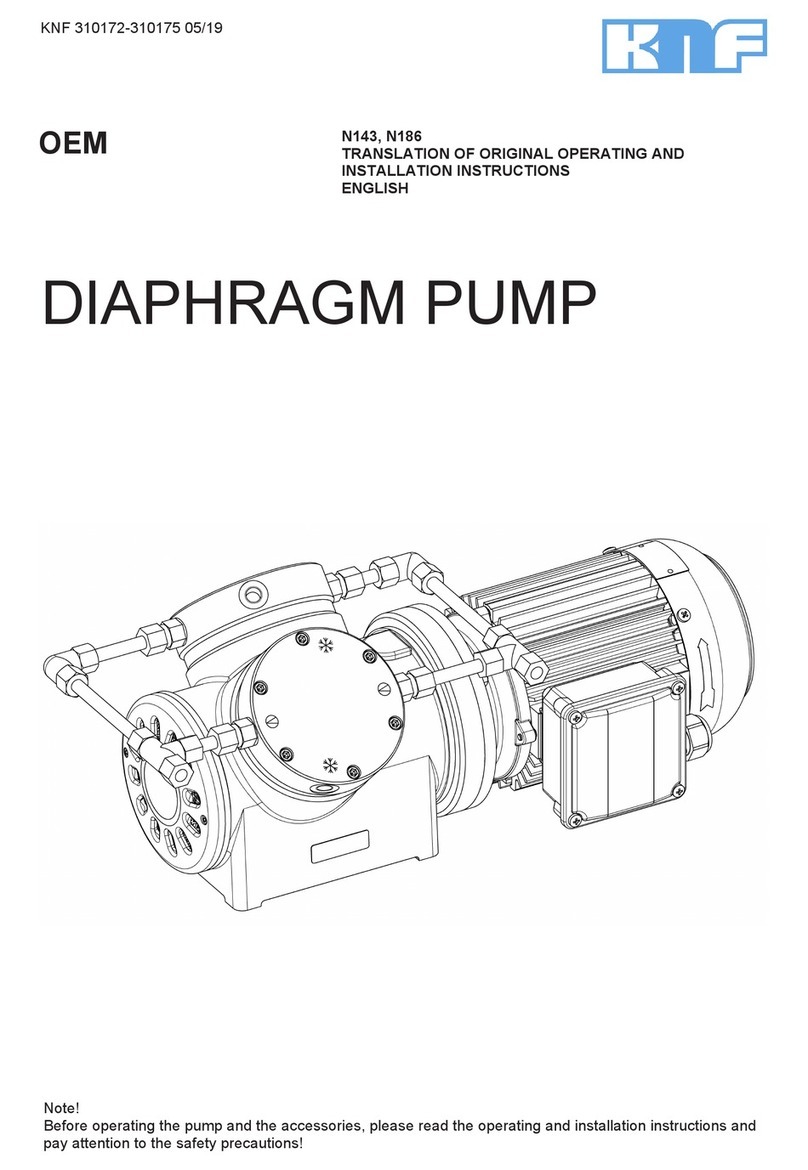
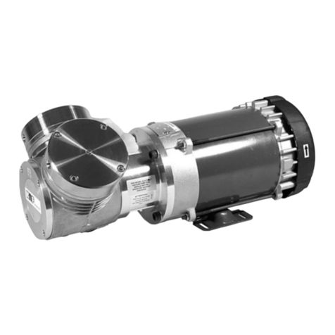
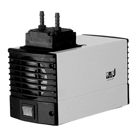
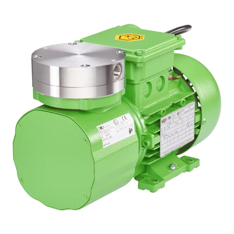
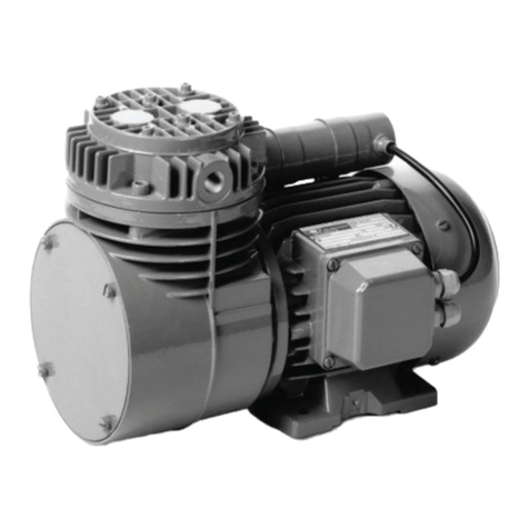
KNF N 813.3 ANE User manual

KNF 121240-121506 09/19
Translation of original Operating and Installation Instructions, english
Diaphragm Vacuum
Pumps and Compressors
N 813.3 ANE
N 813.4 ANE
N 813.5 ANE
Translation of
original Operating
and Installation
Instructions
Read and observe these
Operating and Installation
Instructions!
N 813.3 ANDC-B
N 813.3 AN.29DC-B
N 813.4 ANDC-B
N 813.4 AN.29DC-B
Contents Page
1. About this document................................................................. 2
2. Use........................................................................................... 3
3. Safety ....................................................................................... 4
4. Technical data.......................................................................... 6
5. Assembly and function ........................................................... 13
6. Installation and connection..................................................... 16
7. Operation................................................................................ 22
8. Servicing................................................................................. 29
9. Troubleshooting...................................................................... 34
10. Spare parts and accessories.................................................. 37
11. Returns................................................................................... 38
KNF Neuberger GmbH
Alter Weg 3
79112 Freiburg
Germany
Phone +49 (0)7664 / 5909-0
Fax +49 (0)7664 / 5909-99
E-mail: info@knf.de
www.knf.de

About this document Diaphragm Vacuum Pumps N 813
2 Translation of original Operating and Installation Instructions, english, KNF 121240-121506 09/19
1. About this document
1.1. Use of the Operating and Installation Instruc-
tions
The Operating and Installation Instructions are part of the pump.
➔Forward the Operating and Installation Instructions to any
subsequent owners of the pump.
Customer-specific project pumps (pump models which begin with
"PJ" or "PM") may differ from the Operating and Installation In-
structions.
➔In case of project pumps, take note of any additionally agreed
specifications.
1.2. Symbols and markings
Warning
WARNING
This symbol indicates a potential danger.
It also indicates the possible consequences of failure
to observe the warning. The signal word (i.e. “Warn-
ing”) indicates the level of danger.
➔Here you will see actions for avoiding the danger
and potential consequences.
Danger levels
Signal word
Meaning
Consequences if not observed
DANGER
warns of immediate
danger
Consequences include death
or serious injuries and/or
serious property damage.
WARNING
warns of potential
danger
Death or serious injuries
and/or serious property dam-
age are possible.
CAUTION
warns of a poten-
tially dangerous
situation
Minor injuries or damage to
property are possible.
Tab. 1
Other information and symbols
➔This indicates an activity (step) that must be carried out.
1. This indicates the first step of an activity to be carried out. Any
additional steps are consecutively numbered.
This symbol indicates important information.
Project pumps

Diaphragm Vacuum Pumps N 813 Use
Translation of original Operating and Installation Instructions, english, KNF 121240-121506 09/19 3
2. Use
2.1. Intended use
The pumps are exclusively intended for transferring gases and
vapors.
Owner's responsibility
Only install and operate the pumps under the operating parameters
and conditions described in Chapter 4. Technical data.
Only complete pumps may be taken into service.
Make sure that the installation location is dry and the pump is
protected against water in the form of rain, spray, splashes and
drips.
Before using a medium, check whether the medium can be trans-
ferred danger-free in the specific application case.
Before using a medium, check the compatibility of the materials of
the pump head, diaphragm, and valves with the medium.
Only transfer gases which remain stable under the pressures and
temperatures occurring in the pump.
2.2. Improper use
The pumps must not be operated in an explosive atmosphere.
The pumps are not suitable for transferring dust.
The pumps are not suitable for transferring liquids.
The pumps are not suitable for use with aggressive media. Other
pumps in the KNF product line are designed for use with aggres-
sive media. Please contact us for more information.
The pumps must not be used to create vacuum and pressure
simultaneously.
Never apply positive pressure to the suction side of the pump.
Operating parameters and
conditions
Requirements for
transferred medium

Safety Diaphragm Vacuum Pumps N 813
4 Translation of original Operating and Installation Instructions, english, KNF 121240-121506 09/19
3. Safety
Observe the safety precautions in Chapters
6. Installation and connection and 7. Operation.
The pumps are built according to generally recognized rules of
technology and in accordance with the pertinent occupational
safety and accident prevention regulations. Nevertheless, potential
dangers during use can result in injuries to the user or others or in
damage to the pump or other property.
Only use the pumps when they are in a good technical and proper
working order, in accordance with their intended use, observing the
safety advice within the Operating and Installation Instructions, at
all times.
Make sure that only trained and instructed personnel or specially
trained personnel work on the pumps. This applies especially to
assembly, connection, and servicing work.
Make sure that all personnel have read and understood the Oper-
ating and Installation Instructions, especially the "Safety" chapter.
Observe the accident prevention and safety regulations when
performing any work on the pump and during operation.
Ensure that the pump is separated from the mains and is de-
energized.
When transferring dangerous media, observe the safety regula-
tions for handling such media.
Be aware that the pumps are not designed to be explosion-proof.
Make sure that the temperature of the medium is always sufficient-
ly below its ignition temperature, to avoid ignition or explosion. This
also applies to unusual operating situations.
Note that the temperature of the medium increases when the pump
compresses the medium.
Hence, make sure that the temperature of the medium is sufficient-
ly below its ignition temperature, even when it is compressed to
maximum permissible operating pressure of the pump. The pump's
maximum permissible operating pressure is stated in the Technical
data (see Chapter 4).
Consider any external sources of energy, such as sources of
radiation, that could additionally heat the medium.
In case of doubt, consult the KNF customer service.
All replacement parts should be properly stored and disposed of in
accordance with the applicable environmental protection regula-
tions. Ensure adherence to the pertinent national and international
regulations. This applies especially to parts contaminated with toxic
substances.
For the purposes of Machinery Directive 2006/42/EC, pumps are
“partly completed machinery,” and are therefore to be regarded as
not ready for use. Partly completed machinery may not be com-
missioned until such time as it has been determined that the ma-
Personnel
Working in a
safety-conscious manner
Handling dangerous media
Handling flammable
media
Environmental protection
EC directives / standards

Diaphragm Vacuum Pumps N 813 Safety
Translation of original Operating and Installation Instructions, english, KNF 121240-121506 09/19 5
chine in which the partly completed machinery is to be assembled
conforms to the provisions of the Machinery Directive 2006/42/EC.
The following essential requirements of Annex I of Directive
2006/42/EC (general principles) are applied and observed:
−General Principles No. 1
−No. 1.1.2. / 1.1.3. / 1.3.1. / 1.3.3. / 1.3.4. / 1.4.1. / 1.5.1.* /
1.5.2.* / 1.5.8. / 1.5.9. / 1.7.4. / 1.7.4.1. / 1.7.4.3.
(* only for pumps with AC motor)
As these partly completed machinery are OEM-models the power
supplies and the equipment for disconnecting and switching-off the
partly completed machinery respectively have to be considered
when mounting as well as over-current and overload protective
gear.
In addition a protection against mechanical parts in motion and hot
parts, if existing, has to be provided when mounting.
The pumps conform to the Directive 2011/65/EU.
The following harmonized standards are met:
N 813.3 ANE
N 813.4 ANE
N 813.5 ANE
N 813 ANDC-B
N 813 AN.29DC-B
DIN EN 50581
DIN EN 50581
DIN EN 55014-1/2
DIN EN 61000-6-2/3
DIN EN 61000-3-2/3
DIN EN 60204-1
Tab. 2
All repairs to the pump(s) must be carried out by the relevant KNF
Customer Service team.
Housings with voltage-caring parts may be opened by technical
personnel only.
Use only genuine parts from KNF for servicing work.
Customer services and
repairs

Technical data Diaphragm Vacuum Pumps N 813
6 Translation of original Operating and Installation Instructions, english, KNF 121240-121506 09/19
4. Technical data
N 813.3 ANE
Pneumatic performance
Max. permissible
operating pressure [bar g]
1
Ultimate vacuum [mbar abs.]
3
Flow rate at atm. pressure
[l/min]*
13
Pneumatic connections
Thread size
G 1/8
Ambient and media temperature
Permissible
ambient temperature
+ 5 °C to + 40 °C
Permissible media temperature
+ 5 °C to + 40 °C
Other parameters
Weight [kg]
5.9
Dimensions: L x H x W [mm]
approx. 230 x 148 x 140
Maximum permissible ambient
relative humidity
80 % for temperatures up to
31 °C, decreasing linearly to
50 % at 40 °C
Maximum altitude of installation
[m above sea level]
2000
Electrical data
Voltage / Frequencies
See type label
Max. operating current
Pump power
consumption
Maximum permissible mains
voltage fluctuations
+/- 10 %
Motor protection class
IP 44
Pump materials
Pump head
Aluminium
Diaphragm
EPDM
Valve
EPDM
Tab. 3 * liters in standard state (1013 mbar)
For pumps with thermo switch:
The pumps are fitted with a thermo switch to protect against over-
loading.
WARNUNG
Automatic starting can cause personal injury and
pump damage
When the operation of the pump is interrupted by the
thermal switch, the pump will restart automatically
after cooling down.
➔Take all necessary care to prevent this leading
to a dangerous situation.
Thermo switch

Diaphragm Vacuum Pumps N 813 Technical data
Translation of original Operating and Installation Instructions, english, KNF 121240-121506 09/19 7
N 813.4 ANE
Pneumatic performance
Max. permissible
operating pressure [bar g]
1
Ultimate vacuum [mbar abs.]
0.5
Flow rate at atm. pressure
[l/min]*
13
Pneumatic connections
Thread size
G 1/8
Ambient and media temperature
Permissible
ambient temperature
+ 5 °C to + 40 °C
Permissible media temperature
+ 5 °C to + 40 °C
Other parameters
Weight [kg]
7.5
Dimensions: L x H x W [mm]
308 x 148 x 140
Maximum permissible ambient
relative humidity
80 % for temperatures up to
31 °C, decreasing linearly to
50 % at 40 °C
Maximum altitude of installation
[m above sea level]
2000
Electrical data
Voltage / Frequencies
See type label
Max. operating current
Pump power
consumption
Maximum permissible mains
voltage fluctuations
+/- 10 %
Motor protection class
IP 54
Pump materials
Pump head
Aluminium
Diaphragm
EPDM
Valve
EPDM
Tab. 4 * liters in standard state (1013 mbar)
For pumps with thermo switch:
The pumps are fitted with a thermo switch to protect against over-
loading.
WARNUNG
Automatic starting can cause personal injury and
pump damage
When the operation of the pump is interrupted by the
thermal switch, the pump will restart automatically
after cooling down.
➔Take all necessary care to prevent this leading
to a dangerous situation.
Thermo switch

Technical data Diaphragm Vacuum Pumps N 813
8 Translation of original Operating and Installation Instructions, english, KNF 121240-121506 09/19
N 813.5 ANE
Pneumatic performance
Max. permissible
operating pressure [bar g]
1
Ultimate vacuum [mbar abs.]
1
Flow rate at atm. pressure
[l/min]*
19
Pneumatic connections
Thread size
G 1/8
Ambient and media temperature
Permissible
ambient temperature
+ 5 °C to + 40 °C
Permissible media temperature
+ 5 °C to + 40 °C
Other parameters
Weight [kg]
7.5
Dimensions: L x H x W [mm]
308 x 148 x 140
Maximum permissible ambient
relative humidity
80 % for temperatures up to
31 °C, decreasing linearly to
50 % at 40 °C
Maximum altitude of installation
[m above sea level]
2000
Electrical data
Voltage / Frequencies
See type label
Max. operating current
Pump power
consumption
Maximum permissible mains
voltage fluctuations
+/- 10 %
Motor protection class
IP 54
Pump materials
Pump head
Aluminium
Diaphragm
EPDM
Valve
EPDM
Tab. 5 * liters in standard state (1013 mbar)
For pumps with thermo switch:
The pumps are fitted with a thermo switch to protect against over-
loading.
WARNUNG
Automatic starting can cause personal injury and
pump damage
When the operation of the pump is interrupted by the
thermal switch, the pump will restart automatically
after cooling down.
➔Take all necessary care to prevent this leading
to a dangerous situation.
Thermo switch

Diaphragm Vacuum Pumps N 813 Technical data
Translation of original Operating and Installation Instructions, english, KNF 121240-121506 09/19 9
N 813.3 ANDC-B und N 813.3 AN.29DC-B
Pneumatic performance
Max. permissible
operating pressure [bar g]
1
Ultimate vacuum at nominal
speed [mbar abs.]
3
Flow rate at atm. pressure and
nominal speed [l/min]*
13
Flow rate at atm. pressure and
0.1 V control voltage (only .29
version) [l/min]*
4.2
Pneumatic connections
Thread size
G 1/8
Ambient and media temperature
Permissible
ambient temperature
+ 5 °C to + 40 °C
Permissible media tempera-
ture
+ 5 °C to + 40 °C
Other parameters
Weight [kg]
2.3
Dimensions L x H x W [mm]
145 x 106.5 x 142
Maximum permissible ambient
relative humidity
80 % for temperatures up to 31
°C, decreasing linearly to
50 % at 40 °C
Maximum altitude of installa-
tion [m above sea level]
2000
Electrical data
Motor type
Brushless DC motor
Voltage [V]
24
Control voltage (only .29
version) [V]
0.1…5**
Max. operating current [A]
- for p > patm.
- for p < patm.
1.44
0.96
Starting current
The starting current can be up to
50 % above the maximum
operating current.
Starting ramp [ms]
800
Max. power consumption of
the pump [W]:
- for p > patm.
- for p < patm.
34.56
23.00
Maximum permissible mains
voltage fluctuations
+/- 10 %
Motor protection class
IP 20
Overcurrent limitation of the
motor electronics [A]
7.5
Tab. 6 (part 1) * liters in standard state (1013 mbar)
** further control voltage versions on demand

Technical data Diaphragm Vacuum Pumps N 813
10 Translation of original Operating and Installation Instructions, english, KNF 121240-121506 09/19
Pump materials
Pump head
Aluminium
Diaphragm
PTFE-coated
Valve
EPDM
Tab. 6 (part 2)
The pump is protected against overheating by a temperature
sensor on the motor board and equipped with overcurrent
protection.
If one of these safety functions is triggered or if the maximum
blocking time of the rotor is exceeded due to a fault, the pump
will be shut down and must be manually reset, as follows:
➔Separate pump from the mains.
➔Remove the cause(s) of the fault before restarting.

Diaphragm Vacuum Pumps N 813 Technical data
Translation of original Operating and Installation Instructions, english, KNF 121240-121506 09/19 11
N 813.4 ANDC-B und N 813.4 AN.29DC-B
Pneumatic performance
Max. permissible
operating pressure [bar g]
1
Ultimate vacuum at nominal
speed [mbar abs.]
0.5
Flow rate at atm. pressure and
nominal speed [l/min]*
13
Flow rate at atm. pressure and
0.1 V control voltage (only .29
version) [l/min]*
3.5
Pneumatic connections
Thread size
G 1/8
Ambient and media temperature
Permissible
ambient temperature
+ 5 °C to + 40 °C
Permissible media tempera-
ture
+ 5 °C to + 40 °C
Other parameters
Weight [kg]
3.8
Dimensions L x H x W [mm]
230 x 106.5 x 144
Maximum permissible ambient
relative humidity
80 % for temperatures up to 31
°C, decreasing linearly to
50 % at 40 °C
Maximum altitude of installa-
tion [m above sea level]
2000
Electrical data
Motor type
Brushless DC motor
Voltage [V]
24
Control voltage (only .29
version) [V]
0.1…5**
Max. operating current [A]
- for p > patm.
- for p < patm.
2.7
1.6
Starting current
The starting current can be up to
50 % above the maximum
operating current.
Starting ramp [ms]
800
Max. power consumption of
the pump [W]:
- for p > patm.
- for p < patm.
64.8
38.4
Maximum permissible mains
voltage fluctuations
+/- 10 %
Motor protection class
IP 20
Overcurrent limitation of the
motor electronics [A]
7.5
Tab. 7 (part 1) * liters in standard state (1013 mbar)
** further control voltage versions on demand

Technical data Diaphragm Vacuum Pumps N 813
12 Translation of original Operating and Installation Instructions, english, KNF 121240-121506 09/19
Pump materials
Pump head
Aluminium
Diaphragm
EPDM
Valve
EPDM
Tab. 7 (part 2)
The pump is protected against overheating by a temperature
sensor on the motor board and equipped with overcurrent
protection.
If one of these safety functions is triggered or if the maximum
blocking time of the rotor is exceeded due to a fault, the pump
will be shut down and must be manually reset, as follows:
➔Separate pump from the mains.
➔Remove the cause(s) of the fault before restarting.

Diaphragm Vacuum Pumps N 813 Assembly and function
Translation of original Operating and Installation Instructions, english, KNF 121240-121506 09/19 13
5. Assembly and function
Assembly of N 813.3 ANE
1Inlet (suction side)
2Outlet (pressure side)
3Pneumatic connection
4Motor
Fig. 1: Assembly of N 813.3 ANE
Assembly of N 813.4 ANE
1Inlet (suction side)
2Outlet (pressure side)
3Pneumatic connection
4Motor
Fig. 2: Assembly of N 813.4 ANE

Assembly and function Diaphragm Vacuum Pumps N 813
14 Translation of original Operating and Installation Instructions, english, KNF 121240-121506 09/19
Assembly of N 813.5 ANE
1Inlet (suction side)
2Outlet (pressure side)
3Pneumatic connection
4Motor
Fig. 3: Assembly of N 813.5 ANE
Assembly of N 813.3 ANDC -B und N 813.3 AN.29DC-B
1Inlet (suction side)
2Outlet (pressure side)
3Pneumatic connection
4Motor
Fig. 4: Assembly of N 813.3 ANDC-B und N 813.3 AN.29DC-B

Diaphragm Vacuum Pumps N 813 Assembly and function
Translation of original Operating and Installation Instructions, english, KNF 121240-121506 09/19 15
Assembly of N 813.4 ANDC -B und N 813.4 AN.29DC-B
1Inlet (suction side)
2Outlet (pressure side)
3Pneumatic connection
4Motor
Fig. 5: Assembly of N 813.4 ANDC-B und N 813.4 AN.29DC-B
How diaphragm pumps work
1Outlet valve
2Inlet valve
3Working chamber
4Diaphragm
5Eccentric
6Connecting rod
7Pump drive
Fig. 6: Pump head
Diaphragm pumps transfer, compress (depending on pump ver-
sion), and evacuate gases and vapors.
The elastic diaphragm (4) is moved up and down by the eccentric
(5) and the connecting rod (6). In the downward stroke it aspirates
the gas to be transferred via the inlet valve (2). In the upward
stroke, the diaphragm presses the medium out of the pump head
via the outlet valve (1). The diaphragm hermetically seals the
working chamber (3) from the pump drive (7).

Installation and connection Diaphragm Vacuum Pumps N 813
16 Translation of original Operating and Installation Instructions, english, KNF 121240-121506 09/19
6. Installation and connection
Always install the pumps under the operating parameters and
conditions described in Chapter 4. Technical data.
Observe all safety precautions (see Chapter 3).
6.1. Setting up or installing the pump
➔Choose a safe location (flat surface) for the pump.
➔Before installation, store the pump at the installation location to
bring it up to ambient temperature.
Refer to Fig. 7 (N 813.3 ANE), Fig. 8 (N 813.4 ANE),
Fig. 9 (N 813.5 ANE), Fig. 10 (N 813.3 ANDC-B and N 813.3
AN.29DC-B) or Fig. 11 (N 813.4 ANDC-B and
N 813.4 AN.29DC-B) for the pump dimensions.
Fig. 7: Attachment dimensions of N 813.3 ANE
(dimensional tolerances according to DIN ISO 2768-1, tolerance class V)
Fig. 8: Attachment dimensions of N 813.4 ANE
(dimensional tolerances according to DIN ISO 2768-1, tolerance class V)
Dimensions

Diaphragm Vacuum Pumps N 813 Installation and connection
Translation of original Operating and Installation Instructions, english, KNF 121240-121506 09/19 17
Fig. 9: Attachment dimensions of N 813.5 ANE
(dimensional tolerances according to DIN ISO 2768-1, tolerance class V)
Fig. 10: Attachment dimensions of N 813.3 ANDC-B and N 813.3 AN.29DC-B
(dimensional tolerances according to DIN ISO 2768-1, tolerance class V)
* Connection (X) only for N 813.3 AN.29DC-B

Installation and connection Diaphragm Vacuum Pumps N 813
18 Translation of original Operating and Installation Instructions, english, KNF 121240-121506 09/19
Fig. 11: Attachment dimensions of N 813.4 ANDC-B and N 813.4 AN.29DC-B
(dimensional tolerances according to DIN ISO 2768-1, tolerance class V)
* Connection (X) only for N 813.4 AN.29DC-B
Only for N 813.3 ANE:
➔When setting up or installing the pump, make sure that the fan
can draw in an adequate amount of cooling air.
For pumps with fan: Install the pump so as accidental finger con-
tact is with the fan is impossible.
➔Make sure that the installation location is dry and the pump is
protected against water in the form of rain, spray, splashes and
drips.
The pump motor's IP protection class is provided on the type
plate.
➔Set up or install the pump at the highest point in the system to
prevent condensate from collecting in the pump head.
➔Protect the pump against dust.
➔Protect the pump against grease and oils.
➔Protect the pump against vibration and impact.
Cooling air supply
Installation location

Diaphragm Vacuum Pumps N 813 Installation and connection
Translation of original Operating and Installation Instructions, english, KNF 121240-121506 09/19 19
6.2. Electrical connections
GEFAHR
Extreme danger from electrical shock
➔Only have the pump connected by an authorized
specialist.
➔Only have the pump connected when the power
supply is disconnected.
➔When connecting the device to a power source, the relevant
standards, directives, regulations, and technical standards
must be observed.
➔In the electrical installation, arrangements (complying with EN
60335-1) must be made for disconnecting the pump motor
from the electrical supply.
➔For pumps with AC motor:
The motors of the pump must be protected according to EN
60204-1 (protection against excess current, or overloading).
➔For operating current see type plate.
➔It is recommended that an additional “Emergency Stop” switch
is installed.
➔The pump must be installed so that contact with live parts
(electrical connection) is impossible.
Pumps with AC motor
1. Make sure that the power supply data match the data on the
pump type plate.
The voltage must not vary by more than + 10% and - 10% from
that shown on the type-plate.
2. Connect earth (ground) wire to the motor.
3. Connect motor wires.
Pumps with brushless DC motor
1. Make sure that the power supply data match the data on the
pump type plate.
The voltage must not vary by more than + 10% and - 10% from
that shown on the type-plate.
2. Electrical connect of the pump according to Fig. 12, page 20.
Note the proper polarity (see marking on the motor). Incorrect
lead connection will damage electronics of brushless dc motors
(type designation ending with B). The supply wires have in-
verse-polarity protection on the motor board for this purpose,
while the control-voltage wires do not have this protection
function.

Installation and connection Diaphragm Vacuum Pumps N 813
20 Translation of original Operating and Installation Instructions, english, KNF 121240-121506 09/19
Control voltage may only be applied if the motor controller is
supplied with operating voltage. Otherwise damages can occur
on the motor controller.
Pin Nr.
Pin No.
Farbkodierung
Color coding
Benennung
Description
Elektrische Eigenschaft
Electrical characteristic
1
schwarz
black
DC Spannungsquelle
DC power supply
U0-DC: 5±0.2V
I0: max. 170mA
2
weiß
white
Eingang Steuerspannung
Control voltage input
UIN-DC: 0…5V (PIN-MAX: ≤5mW)
fPWM-IN: 100Hz±50Hz
duty cycle: 0…100%
RIN:≥12.2kΩ @1kHz
3*
grau
grey
Masse
Ground
4
lila
purple
Ausgang Fehlermeldung
Error signal output
UERROR-0-DC: ≤0.6V / UERROR-1-DC: ≥4.5V…U0-DC
5*
blau
blue
Masse
Ground
UON-DC: ≤0.9V
UOFF-DC: ≥4.2V…U0-DC
6
grün
green
Eingang Remote EIN/AUS
Input Remote ON/OFF
7
gelb
yellow
Ausgang Drehzahlsignal
Speed signal output
PWM-OUT
fPWM-OUT: 50Hz
UPWMF-OUT: U0-DC
duty cycle: 0…100%
FREQ-OUT
fFREQ-OUT: n
1 pulse / revolution
UFREQ-OUT: U0-DC
8*
orange
orange
Masse
Ground
Zulässige Spannung an den Steuereingängen
allowable voltage at control inputs
UDC: max. 5.5V
Zulässige Strombelastbarkeit an den Steuerausgängen
allowable ampacity at control outputs
I: max. 10mA
Fig. 12: Connection plan motor electronics (connection (X) only for N 813._ AN.29DC-B)
* Ground Pin 3, 5 and 8 are connected with each other
If Pin 1 is simultaneously used as control voltage specification
for Pin 2, please contact the KNF customer services (see last
page for telephone number).
This manual suits for next models
6
Table of contents
Other KNF Water Pump manuals

KNF
KNF N838 DC Series User manual

KNF
KNF N936 User manual

KNF
KNF NMP 03 KP DC-B1 User manual

KNF
KNF FK 1100 User manual

KNF
KNF Laboport N820 User manual

KNF
KNF UN035ANI EX User manual

KNF
KNF NPK 25 AC User manual

KNF
KNF N 143 AV.12 E Assembly instructions

KNF
KNF NF 2.35 User manual

KNF
KNF N680 EX User manual
Popular Water Pump manuals by other brands

SPX FLOW
SPX FLOW Johnson Pump 10-13635-01 instruction manual

AQUATECH
AQUATECH Aquajet RV Series User manual and installation guide

Little Giant
Little Giant 2E-NYS manual

Little Giant
Little Giant EC-1-DV owner's manual

SPX FLOW
SPX FLOW Power Team PB102-1 Parts list and operating instructions

Astral Pool
Astral Pool MICRO UP Series Programming instructions