Knick Unical 9000 User manual

Protos II
Service Switch
Unical9000
Error
Meas
Service
User Manual Unical 9000/Protos II 4400
Process Analysis System
www.knick.de
Read before installation.
Keep for future use.

Unical 9000/Protos II 4400
2
Supplemental Directives
READ AND SAVE THIS DOCUMENT FOR FUTURE REFERENCE. BEFORE ATTEMPTING TO ASSEMBLE, INSTALL,
OPERATE OR MAINTAIN THE PRODUCT, PLEASE ENSURE A COMPLETE UNDERSTANDING OF THE INSTRUC-
TIONS AND RISKS DESCRIBED HEREIN. ALWAYS OBSERVE ALL SAFETY INFORMATION. FAILURE TO COMPLY
WITH INSTRUCTIONS IN THIS DOCUMENT COULD RESULT IN SERIOUS INJURY AND/OR PROPERTY DAMAGE.
THIS DOCUMENT IS SUBJECT TO CHANGE WITHOUT NOTICE.
These supplemental directives explain how safety information is laid out in this document and what
content it covers.
Safety Chapter
This document's safety chapter is designed to give the reader a basic understanding of safety. It illus-
trates general hazards and gives strategies on how to avoid them.
Warnings
This document uses the following warnings to indicate hazardous situations:
Symbol Category Meaning Remark
WARNING Designates a situation that can lead to death or serious
(irreversible) injury.
The warnings contain
information on how to
avoid the hazard.
CAUTION Designates a situation that can lead to slight or moderate
(reversible) injury.
None NOTICE Designates a situation that can lead to property or
environmental damage.
Symbols Used in this Document
Symbol Meaning
Reference to additional information
Interim or final result in instructions for action
Sequence of figures attached to an instruction for action
Item number in a figure
Item number in text
Related Documents
• Retractable fitting User Manual. ➜www.knick.de
• Protos II 4400 industrial transmitter User Manual. ➜www.knick.de
• Protos modules User Manuals. ➜www.knick.de
• Sensor User Manual. ➜www.knick.de

Unical 9000/Protos II 4400
3
Table of Contents
1 Safety............................................................................................................................................. 5
1.1 Intended Use ......................................................................................................................................................... 5
1.2 Personnel Requirements ................................................................................................................................... 5
1.3 Safeguards.............................................................................................................................................................. 6
1.4 Residual Risks ........................................................................................................................................................ 6
1.5 Hazardous Substances....................................................................................................................................... 7
1.6 Operation in Explosive Atmospheres ........................................................................................................... 7
1.7 Operation and Installation................................................................................................................................ 7
1.8 Maintenance and Spare Parts.......................................................................................................................... 8
1.9 Safety Training ...................................................................................................................................................... 8
2 Product.......................................................................................................................................... 9
2.1 Package Contents ................................................................................................................................................ 9
2.2 Product Identification......................................................................................................................................... 9
2.2.1 Example of a Version............................................................................................................................. 9
2.2.2 Product Code ........................................................................................................................................... 10
2.3 Nameplates ............................................................................................................................................................ 11
2.4 Symbols and Markings on the Product........................................................................................................ 12
2.5 Process Analysis System Design ..................................................................................................................... 13
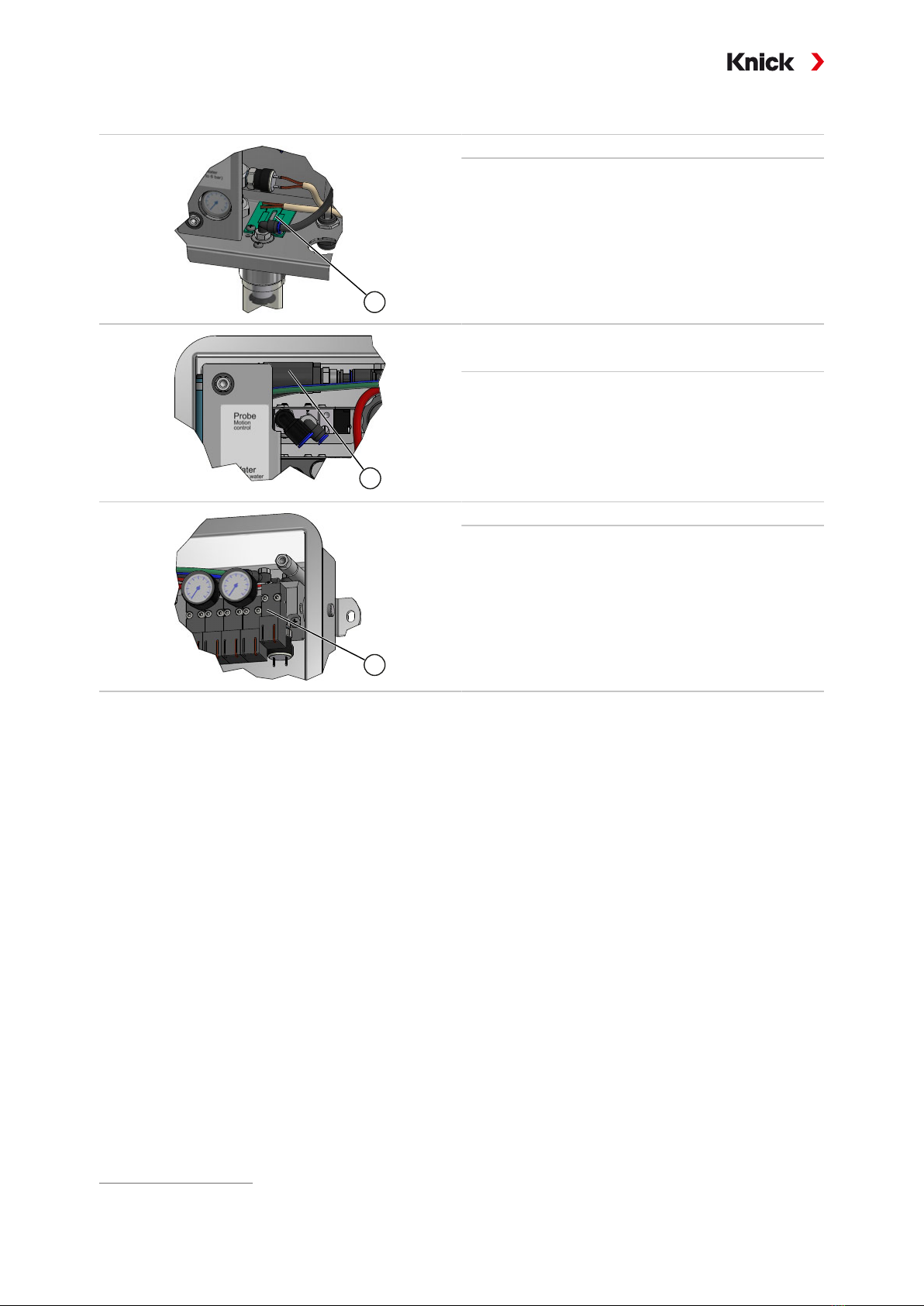
2.5.1 Electro-Pneumatic Controller Design and Function.................................................................. 14
2.5.2 Media Adapter with Metering Pumps and Containers Design and Function .................. 17
2.5.3 Service Switch Design and Function............................................................................................... 18
2.5.4 Process Connection Design and Function .................................................................................... 19
2.5.5 Changes for Different Conditions..................................................................................................... 19
3 Installation .................................................................................................................................... 20
3.1 General Installation Instructions .................................................................................................................... 20
3.2 Mechanical Installation...................................................................................................................................... 21
3.2.1 Wall Installation....................................................................................................................................... 21
3.2.2 Pipe Installation ...................................................................................................................................... 23
3.2.3 Process Connection Installation........................................................................................................ 25
3.2.4 Installing the Retractable Fitting and Media Adapter Supply................................................ 26
3.2.5 Water Supply Installation .................................................................................................................... 30
3.2.6 Compressed Air Supply Installation ................................................................................................ 31
3.2.7 Installing the Media Adapter with Metering Pumps and Containers.................................. 32
3.2.8 Industrial Transmitter Installation .................................................................................................... 32
3.2.9 Retractable Fitting Installation.......................................................................................................... 32
3.3 Electrical Installation........................................................................................................................................... 33
3.3.1 Service Switch Electrical Installation............................................................................................... 37
3.3.2 Media Adapter Electrical Installation .............................................................................................. 37
3.4 Process Control System Installation .............................................................................................................. 38
4 Commissioning ............................................................................................................................. 40

Unical 9000/Protos II 4400
4
5 Parameter Setting ........................................................................................................................ 41
5.1 Protos Parameter Setting .................................................................................................................................. 41
5.1.1 Calibration Timer .................................................................................................................................... 43
5.1.2 Time Control............................................................................................................................................. 44
5.1.3 Control and Service Programs ........................................................................................................... 47
5.1.4 Configuring the Program Flow.......................................................................................................... 59
5.1.5 Calibration................................................................................................................................................. 60
5.1.6 Installation ................................................................................................................................................ 61
6 Operation ...................................................................................................................................... 66
6.1 Metering Pump: Filling the Containers ........................................................................................................ 66
6.2 Progress Display ................................................................................................................................................... 68
7 Diagnostics.................................................................................................................................... 70
7.1 Protos Diagnostic Functions ............................................................................................................................ 70
7.2 Relay Contacts....................................................................................................................................................... 74
8 Maintenance ................................................................................................................................. 76
8.1 Inspection and Maintenance........................................................................................................................... 76
8.1.1 Protos Maintenance Functions.......................................................................................................... 76
8.1.2 Pilot Valve Functional Test................................................................................................................... 80
8.2 Corrective Maintenance .................................................................................................................................... 81
8.2.1 Corrective Maintenance on the Metering Pumps ...................................................................... 81
8.2.2 Replacing the Air Pressure Switch.................................................................................................... 83
8.2.3 Replacing the Water Pressure Switch.............................................................................................. 84
8.2.4 Knick Repair Service .............................................................................................................................. 84
9 Troubleshooting ........................................................................................................................... 85
9.1 Protos Malfunction Message ........................................................................................................................... 90
10 Decommissioning......................................................................................................................... 91
10.1 Unical: Removal .................................................................................................................................................... 91
10.2 Return....................................................................................................................................................................... 91
10.3 Disposal ................................................................................................................................................................... 91
11 Spare Parts, Accessories, and Tools............................................................................................. 92
11.1 Spare Parts.............................................................................................................................................................. 92
11.2 Accessories ............................................................................................................................................................. 96
12 Dimension Drawings.................................................................................................................... 98
13 Specifications................................................................................................................................102
14 Annex.............................................................................................................................................105
Symbols and Markings on the Display .......................................................................................107
Abbreviations ...............................................................................................................................109
Index..............................................................................................................................................110

Unical 9000/Protos II 4400
5
1 Safety
This document contains important instructions for the use of the product. Always follow all
instructions and operate the product with caution. If you have any questions, please contact Knick
Elektronische Messgeräte GmbH & Co. KG (sometimes hereafter referred to as “Knick”) using the
information provided on the back page of this document.
1.1 Intended Use
The Unical 9000 is an electro-pneumatic controller for fully automatic process control of pH
measurements.
The sensor is immersed in the process medium (PROCESS limit position) by the retractable fitting’s
probe (sensor housing or immersion tube). In the service position (SERVICE limit position), the sensor
can be cleaned, calibrated, or replaced. The cleaning or calibration media are automatically supplied
via the process connection and media adapter.
Unical 9000 can be used in combination with the following products:
Retractable fittings SensoGate
Ceramat
Industrial transmitter Protos II 4400
Further information can be found in the relevant product documentation.
The defined operating conditions must be observed when using this product. ➜Specifications, p. 102
USE CAUTION AT ALL TIMES WHEN INSTALLING, USING, MAINTAINING OR OTHERWISE INTERACTING WITH
THE PRODUCT. ANY USE OF THE PRODUCT EXCEPT AS SET FORTH HEREIN IS PROHIBITED, AND MAY RESULT
IN SERIOUS INJURY OR DEATH, AS WELL AS DAMAGE TO PROPERTY. THE OPERATING COMPANY SHALL BE
SOLELY RESPONSIBLE FOR ANY DAMAGES RESULTING FROM OR ARISING OUT OF AN UNINTENDED USE OF
THE PRODUCT.
All references to “device,” “product,” “Unical9000,” “ProtosII4400,” “MSU4400‑180,” “COMPA3400‑081”
refer to the various versions, both non-Ex and Ex, of the relevant device.
The Unical 9000X version is certified for operation in hazardous locations.
➜Operation in Explosive Atmospheres, p. 7
1.2 Personnel Requirements
The operating company shall ensure that any personnel using or otherwise interacting with the
product is adequately trained and has been properly instructed.
The operating company shall comply and cause its personnel to comply with all applicable laws, regu-
lations, codes, ordinances and relevant industry qualification standards related to product. Failure to
comply with the foregoing shall constitute a violation of operating company’s obligations concerning
the product, including but not limited to an unintended use as described in this document.

Unical 9000/Protos II 4400
6
1.3 Safeguards
1
Water Leakage Detection
There is a circuit board (1) on the base of the controller’s
housing. Its contact surfaces detect the presence of elec-
trically conductive liquids on them. If, for example, water
leaks out, a current flow generates the following error
message in the industrial transmitter: Leakage Sensor
(U224)
1
Sensor Dismount Guard1)
The sensor dismount guard (1) measures the pressure
drop or variations that can occur during operation of the
retractable fitting. A pressure drop is a sign that there is
no sensor in the retractable fitting. Movement of the re-
tractable fitting to the process position (PROCESS limit
position) is stopped. Message in the industrial transmit-
ter: Immersion Lock (U221)
1
Safety Valve
The safety valve (1) is connected upstream of all pilot
valves. When you press the service switch, all pilot valves
are depressurized by the safety valve.
1.4 Residual Risks
The product has been developed and manufactured in accordance with generally accepted safety
rules and regulations, as well as an internal risk assessment. Despite the foregoing, the product may
among others bear the following risks:
The effects of moisture, ambient temperature, chemicals, and corrosion can negatively impact the safe
operation of the product. Observe the following instructions:
• Observe the permissible ambient temperature. Alternatively, use protective cabinets and heatable
process connections. ➜Specifications, p. 102
• Protect the controller from direct sunlight.
• If using aggressive chemical process media, adhere to and adjust the inspection and maintenance
intervals accordingly.
Drinking Water Connection
If the Unical 9000 is connected to the drinking water supply, impurities caused by the rinse and
process media may occur. Note the information in EN1717. Install a suitable check valve at the water
or rinse connection. ➜Accessories, p. 96
1) Applies only when using a Ceramat retractable fitting.

Unical 9000/Protos II 4400
7
1.5 Hazardous Substances
IN THE EVENT OF ANY CONTACT WITH HAZARDOUS SUBSTANCES OR OTHER INJURY HEREUNDER, SEEK IM-
MEDIATE MEDICAL ATTENTION OR FOLLOW APPLICABLE PROCEDURES TO ADDRESS HEALTH AND SAFETY
OF PERSONNEL. FAILURE TO SEEK IMMEDIATE MEDICAL ATTENTION MAY RESULT IN SERIOUS INJURY OR
DEATH.
In certain situations (e.g., sensor replacement or corrective maintenance), personnel may come into
contact with the following hazardous substances:
• Process medium
• Cleaning medium
• Buffer and calibration solutions
The operating company is responsible for conducting a risk assessment.
See the relevant manufacturers’ safety data sheets for hazard and safety instructions on handling
hazardous substances.
1.6 Operation in Explosive Atmospheres
The Unical 9000X is certified for operation in explosive atmospheres.
• EU-Type Examination Certificate KEMA04ATEX1036
• IECEx Certificate of Conformity IECExDEK22.0022
The conditions for installation and operation in explosive atmospheres can be found on the corre-
sponding certificates.
Observe all applicable local and national codes and standards for the installation of electrical equip-
ment in explosive atmospheres. For further guidance, consult the following:
• IEC60079-14
• EU directives 2014/34/EU and 1999/92/EC(ATEX)
Modules which have already been used shall be subjected to a professional routine test before they
may be operated in another type of protection.
• Before the product is commissioned, the operator must provide proof that the product is ap-
proved for connection to other equipment (including cables and wires). Connecting components
designed for explosive atmospheres and those not designed for explosive atmospheres (mixed
equipping) is not permitted.
Unical 9000X Markings
Information on the Unical 9000X markings is available in the enclosed certificates.
Electrostatic Discharge
Some materials used in the product are electrostatic insulators and may be electrostatically charged.
To prevent electrostatic discharge, please observe the following instructions:
• Clean non-metallic components with a damp cloth only, and allow them to dry.
Certificates
The current versions of the applicable certificates are available at www.knick.de.
1.7 Operation and Installation
All national and local regulations relating to the installation and operation of the product in force at
the destination must be followed.

Unical 9000/Protos II 4400
8
1.8 Maintenance and Spare Parts
Preventive Maintenance
Preventive maintenance can keep the product in good condition and minimize downtimes. Knick
provides recommended inspection and maintenance intervals. ➜Maintenance, p. 76
Spare Parts
For professional corrective maintenance of the product, only use Knick genuine spare parts. Usage of
any other spare parts shall constitute an unintended use of the product.
Repair Service
The Knick Repair Service offers professional corrective maintenance for the product to the original
quality. Upon request, a replacement unit can be obtained for the period of the repair.
Further information can be found at www.knick.de.
1.9 Safety Training
Upon request, Knick Elektronische Messgeräte GmbH & Co. KG will provide safety briefings and
product training during initial commissioning of the product. More information is available from the
relevant local contacts.

Unical 9000/Protos II 4400
9
2 Product
2.1 Package Contents
• Unical 9000 in the version ordered
• Service switch
• 2 identical cables (to connect Unical 9000 to the service switch and Unical 9000 to the Protos in-
dustrial transmitter)
• Cable with plug (to connect Unical 9000 to the media adapter)
• Hook wrench
• User Manual
• EU Declaration of Conformity1)
• Control Drawing1)
• Test Report 2.2 according to EN 10204
2.2 Product Identification
The different versions of the Unical 9000 are encoded in a product code.
The product code is stated on the nameplate, the delivery note, and the product packaging.
➜Nameplates, p. 11
2.2.1 Example of a Version
Unical 9000 –XSG1A222CE–400
Explosion protection For hazardous area Zone1 X –
Housing Stainless steel, polished S –
Media connection (calibration
and rinse function)
14 m (seal: EPDM) G –
Media interface Without 0 –
Media adapter with port I-III With (seal: EPDM) A –
Port I Metering pump with 3-liter container (EPDM) 2 –
Port II Metering pump with 3-liter container (EPDM) 2 –
Port III Metering pump with 3-liter container (EPDM) 2 –
Supplementary air purging
Aux1
With C –
Supplementary external valve
Aux2
With E –
Special version With protective cabinet and heater, Ex –400
1) Part of package contents only for Ex-approved products.

Unical 9000/Protos II 4400
10
2.2.2 Product Code
Unical 9000 –__________–___
Explosion protection For hazardous area Zone 1 X –
Without N –
Housing Steel, coated C –
Stainless steel, polished S –
Media connection (rinse
function only)
5 m (seal: FKM) 1 0 –
10 m (seal: FKM) 2 0 –
15 m (seal: FKM) 5 0 –
5 m (seal: EPDM) A 0 –
10 m (seal: EPDM) B 0 –
15 m (seal: EPDM) E 0 –
Media connection (calibration
and rinse function)
5 m (seal: FKM) 3 –
10 m (seal: FKM) 4 –
14 m (seal: FKM) 7 –
17 m (seal: FKM) 6 –
5 m (seal: EPDM) C –
10 m (seal: EPDM) D –
14 m (seal: EPDM) G –
17 m (seal: EPDM) F –
Media interface With1) 1 –
Without2) 0 –
Media adapter with port I-III With (seal: FKM) 1 –
With (seal: EPDM) A –
Without 0 –
Port I Metering pump with 3-liter container (EPDM) 2 –
Without 0 –
Port II Metering pump with 3-liter container (EPDM) 2 –
Without 0 –
Port III Metering pump with 3-liter container (EPDM) 2 –
Metering pump with 3-liter container (FKM) B –
Without 0 –
Supplementary air purging
Aux1
With C –
Without N –
Supplementary external valve
Aux2
With E –
Without N –
Special version Without –000
With protective cabinet, non-Ex –100
With protective cabinet and heater, non‑Ex –200
With protective cabinet, Ex –300
With protective cabinet and heater, Ex –400
1) Interface for connecting retractable fittings from other manufacturers.
2) For retractable fittings WA130, WA150, WA153, WA154, or WA160.

Unical 9000/Protos II 4400
11
2.3 Nameplates
The Unical 9000 electro-pneumatic controller is identified by a nameplate on the outside of the right
wall.
Unical Nameplate, Without ATEX Approval
1
2
3
4
5 6 7
8
9
10
1Manufacturer’s address with designation of origin 6IP protection
2Permissible ambient temperature 7CE mark
3Type (product code) 8Serial number
4Manufacturer 9Product number/Serial number/Production year
and week
5Product line 10 Barcode (item production number/serial number)
Accessory Nameplates, Without ATEX Approval
1
2
3
4
5
67
1
2
3
4
5
67
1
2
3
4
5
67
1
2
3
4
5
67
1Note 5Manufacturer
2Serial number 6CE mark
3Type 7Manufacturer’s address with designation of origin
4Product line

Unical 9000/Protos II 4400
12
Unical Nameplate, With ATEX Approval
1
2
3
4
5
6 7
8
9
10
11
1213
1Special conditions and danger points 8Serial number
2Conformity mark with identification number 9Permissible ambient temperature
3ATEX marking/information on explosion protection 10 Product number/Serial number/Production year
and week
4Manufacturer’s address with designation of origin 11 Barcode (item production number/serial number)
5Type (product code) 12 IP protection
6Manufacturer 13 Read the documentation
7Product line
Accessory Nameplates, With ATEX Approval
1
2
3
4
5
6
7 8
9
1
2
3
4
5
67 8
9
1
2
3
4
5
67 8
9
1Manufacturer’s address with designation of origin 6Product line
2Note 7Manufacturer
3EU Type Examination Certificate test number 8ATEX marking
4Serial number 9Conformity mark with identification number
5Type
2.4 Symbols and Markings on the Product
Special conditions and danger points! Observe the safety information and instructions on safe use of the
product as outlined in the product documentation.
Reminder to read the documentation.
CE marking with identification number1) of the notified body involved in production control.
ATEX marking1) of the European Union for operation of the Unical 9000X in hazardous locations.
➜Operation in Explosive Atmospheres, p. 7
IP65 protection code: The product is dust-tight and offers complete protection against contact as well as
protection against water projected (by a nozzle) from any direction.
1) Dependent on the ordered version. ➜Product Code, p. 10

Unical 9000/Protos II 4400
13
2.5 Process Analysis System Design
The figure shows an example installation of a Knick process analysis system.
Protos II
ServiceSwitch
Unical9000
Error
Meas
Service
1
2
3
4
5
6 7
8
9
10
11
12
1Probe (sensor housing/immersion tube)1) 7Electro-pneumatic controller
2Retractable fitting1) 8Protos industrial transmitter1)
3Retractable fitting: outlet hose1) 9Cable (to connect Unical 9000 to the service switch)
4Sensor cable1) 10 Cable (to connect Unical 9000 to the media adapter)
5Process connection 11 Cable with plug (to connect Unical 9000 to the Protos
industrial transmitter)
6Service switch 12 Media adapter with metering pumps and container
1) Not included in the package contents.

Unical 9000/Protos II 4400
14
2.5.1 Electro-Pneumatic Controller Design and Function
The electro-pneumatic controller controls the movements of the probe (sensor housing/immersion
tube) into the process and service positions and the calibration and cleaning media supply lines.
Air
(4 to 7 bar)
1
2
3
4
5
1Media supply 4Valve block
2Retractable fitting and media adapter supply 5Terminals
3Sensor dismount guard

Unical 9000/Protos II 4400
15
Media Supply
Air
(4 to 7 bar)
Air
(4 to 7 bar)
1
3
2
4
5
7
8
9
10
6
1Water pressure manometer 6Grounding connection
2Compressed air connection 7Exhaust air tube (Aux 1)
3Water connection 8Housing with top piece equipotential bonding
4Feedthrough for media connection 9Compressed air filter
5Cable gland (6x) 10 Water separator
Retractable Fitting and Media Adapter Supply
Air
(4 to 7 bar)
Air
(4 to 7 bar)
1
2
3
4
5
1Compressed air for the process and service
positions
4Option Aux 1:1) compressed air for cleaning and rinsing
2Water for cleaning and rinsing 5Option Aux 2:1) compressed air for various applications
3Compressed air for media adapter
1) Availability is dependent on the ordered version. ➜Product Code, p. 10

Unical 9000/Protos II 4400
16
Valve Block
Air
(4 to 7 bar)
Air
(4 to 7 bar)
1 2 3 4
5678
1Pressure regulator for setting the supply pressure 5Process and service position pilot valve
2Air pressure manometer for pressure regulator (1) 6Water pilot valve
3Pilot pressure manometer 7Option: Aux 1 pilot valve
4Safety valve 8Option: Aux 2 pilot valve
Terminals
Air
(4 to 7 bar)
Air
(4 to 7 bar)
1
2
1Terminal assignments 2Terminals

Unical 9000/Protos II 4400
17
2.5.2 Media Adapter with Metering Pumps and Containers Design and Function
The media adapter with metering pumps and containers stores the calibration and cleaning media.
These media are supplied to the retractable fitting via the metering pumps and the process
connection.
1
3
2
1Container 3Media adapter
2Metering pumps
Media Adapter
1
2
3
4
5
III
III
1Ports I to III 4Wall holder
2Process connection 5Blind plate holder
3Unical electro-pneumatic controller connection

Unical 9000/Protos II 4400
18
Metering Pump with Container
1
2
3
4
5
6
7
1Container (approx. capacity 3 l) 5Check valve
2Top piece with funnel tube 6Float switch
3Media adapter connection 7Suction tube
4Pump housing
2.5.3 Service Switch Design and Function
The service switch supplies the signal to move the probe (sensor housing/immersion tube) to the
service position (SERVICE limit position). The system enters service mode. ➜Service Mode, p. 76
The service switch must be pressed again to exit service mode.
Service Switch
Unical 9000
Error
Meas
Service
1
2
3
4
5
1Cable gland 4Error LED (red)
2Switch 5Wall holder
3Service LED (yellow)
LED Messages
Error LED
(Red)
Service LED
(Yellow)
Status
Blinking Retractable fitting in PROCESS position.
Service switch actuated.
Lit up Retractable fitting in SERVICE position, safety valve depressurizes pilot valves.
Lit up SERVICE position not reached. ➜Troubleshooting, p. 85

Unical 9000/Protos II 4400
19
2.5.4 Process Connection Design and Function
The process connection connects the Unical 9000 electro-pneumatic controller, the media adapter to
metering pumps and the retractable fitting.
23
456
7 8 9
11
1
10
1Retractable fitting connection (multiplug) 7Limit position check-back cable
2Media adapter with metering pumps connection 8Water connection (transparent)
3Unical 9000 electro-pneumatic controller connection 9Slotted nut
4Media adapter compressed air supply (red band) 10 O-ring 27 x 3 mm
5Service position compressed air Ø 6 mm (green) 11 Fastening screws
6Process position compressed air Ø 8 mm (green)
2.5.5 Changes for Different Conditions
The Unical 9000 can be adapted to changed conditions by the customer. Prior to making any changes,
contact Knick Elektronische Messgeräte GmbH & Co. KG. The following are examples of possible
changes:
• Installation of an additional air pressure valve
Any changes may result in deviations between the information on the nameplate and the actual ver-
sion of the Unical 9000. The operating company must assess and document the changes. In the event
of a change to the version, the product must be identified accordingly.
It is recommended that changes to the Unical 9000 be carried out by the Knick Repair Service. After
making the necessary changes, a functional and pressure test is carried out and, if necessary, a modi-
fied nameplate is attached. ➜Knick Repair Service, p. 84

Unical 9000/Protos II 4400
20
3 Installation
3.1 General Installation Instructions
• The Unical 9000 can be installed on a wall or pipe.
• The mounting location must have sufficient strength and be vibration-free.
• If installing outdoors, pay attention to the ambient temperature. ➜Specifications, p. 102
Take protective measures if necessary.
• Install the service switch near the retractable fitting.
Note: All dimensions are given in millimeters [inches].
1
2
3
1Electro-pneumatic controller 3Floor
2Media adapter with metering pumps and containers
The distances are determined by the standard lengths of the cables.
Other manuals for Unical 9000
1
This manual suits for next models
1
Table of contents
Other Knick Analytical Instrument manuals
Popular Analytical Instrument manuals by other brands

Hamamatsu
Hamamatsu ENERGETIQ LDTLS TLS-EQ-77H Operation manual

YOKOGAWA
YOKOGAWA OX100 user manual

Powerfix Profi
Powerfix Profi KH 2927-1 operating instructions

Teledyne
Teledyne 4040 Instruction, operating and maintenance manual

VOLTCRAFT
VOLTCRAFT BS-100XIP operating instructions

ADA INSTRUMENTS
ADA INSTRUMENTS COSMO 150 VIDEO operating manual