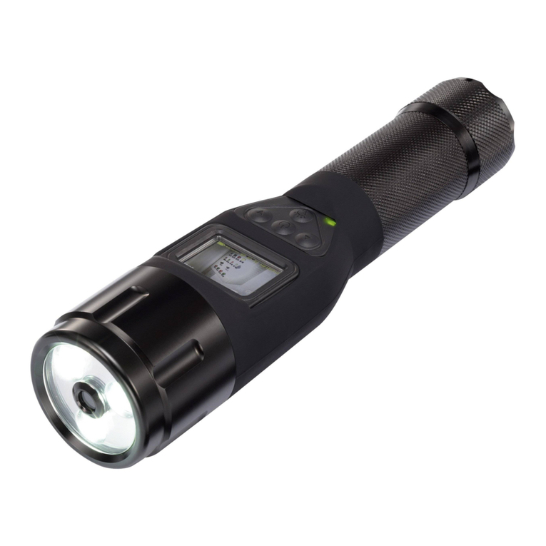
YOKOGAWA OX100 User manual

User's
Manual
IM 11M10A01-01E
OX100
General-Purpose Oxygen Analyzer
IM 11M10A01-01E
2nd Edition

i
Safety Precautions
IM 11M10A01-01E
IM 11M10A01-01E
2nd Edition: Oct. 2005 (YK)
All Rights Reserved, Copyright © 2000, Yokogawa Electric Corporation
Safety Precautions
This Analyzer is designed for instrument panel or rack mounting.
To ensure safe operation of this instrument, strictly observe the following safety
instructions during operation, maintenance and servicing. Yokogawa will not be
responsible or liable for damage caused by not following these instructions when
using the instrument.
• Symbols
The following graphical symbols are used in this manual.
WARNING
Emphasizes instructions that must be observed – or electric shock and injury to, or death
of, personnel could result.
CAUTION
Emphasizes instructions that must be observed – or damage to hardware, software or
system crashes, could result.
NOTE
Emphasizes points that require special attention in understanding the operation and
functions.
Notes on Instruction Manuals
• Please pass on the Instruction Manuals to the end user.
• Please read the manual thoroughly before using the instrument.
• This manual describes the functions of the product in detail; they do not imply any
warranty that the instrument will meet the special needs of the user.
• No part of the manual may be reproduced without prior written consent from
Yokogawa.
• Yokogawa reserves the right to improve the instrument and manuals at any time,
without notice or obligation.
• If you have any questions about the manuals, or feel that there are mistakes or
omissions, please contact our sales representative or your local distributor/agent.

IM 11M10A01-01E
ii
Maintenance, Safety, and Product Modification
• In order to protect the system controlled by the instrument, and the instrument itself,
and to ensure safe operation, observe the safety precautions described in this manual.
•If any protective or safety circuitry is required for the system used with this instru-
ment, or for the instrument itself, prepare and install it. Do not change the internal
parts or circuitry of the instrument in any way.
Disclaimers (Limitation of Liability)
Yokogawa grants no warranties other than the express warranty set forth under the
warranty provisions.
Yokogawa shall not be liable to you or any third party for any damage, including
consequential or incidental damages, arising out of or in connection with the use of this
equipment, defects beyond our knowledge, or any other contingency beyond our control.
WARNING
High temperature, take care
When the sensor is powered on, the sensor tip gets very hot. Be careful not to touch it.
4-20mA
ENT..
%
ppm
FAILALM
1000ppmAIR
MODE
SET
Caution: Sensor is HOT
F1.EPS
Power
Be sure to check the power supply voltage before turning on the power.
Grounding
Be sure to connect a Class D (100Vor less) ground before turning on the power, to
minimize the possibility of shock.
Need for Grounding
Do not cut the internal or external protective ground wire, or remove the ground wire
from the terminal. This creates a shock hazard.
Do not Operate without Protective Grounding and Fuse
Do not operate the instrument without protective grounding and correct fuse.
Fuse
For safety, this product is fused internally. It is recommended that you ask the local
service representative to change the fuse; do not either change it yourself, or open the
case to check the fuse. Turn off the power switch and disconnect the instrument from
the power before changing the fuse. Do not use a fuse of different type or size, or short-
circuit the fuse holder.

iii
Safety Precautions
IM 11M10A01-01E
Environmental Restrictions
Danger: Do not use this instrument in a flammable, explosive, or steamy environment.
Do not try to measure gases with traces of redox gas, corrosive gas, or organic silicone
gas.
Keep Hands Out
While voltage is applied, keep hands out. Internal parts should be replaced by our
service representative, or by an authorized person.
External Connections
Before wiring, to minimize the possibility of shock, disconnect power from the instru-
ment. Also check ground connection to this instrument, to the system being measured,
and to any associated external control equipment

IM 11M10A01-01E
iv
rAfter-Sales Warranty
dDo not modify the product.
dDuring the warranty period, for repair under warranty carry or send the product to the
local sales representative or service office. Yokogawa will replace or repair any
damaged parts and return the product to you.
dBefore returning a product for repair under warranty, provide us with the model
name and serial number and a description of the problem. Any diagrams or data
explaining the problem would also be appreciated.
dIf we replace the product with a new one, we won’t provide you with a repair report.
dYokogawa warrants the product for the period stated in the pre-purchase quotation.
Yokogawa shall conduct defined warranty service based on its standard. When the
customer site is located outside of the service area, a fee for dispatching the
maintenance engineer will be charged to the customer.
dIn the following cases, customer will be charged repair fee regardless of warranty
period.
• Failure of components which are out of scope of warranty stated in instruction
manual.
• Failure caused by usage of software, hardware or auxiliary equipment, which
Yokogawa did not supply.
• Failure due to improper or insufficient maintenance by user.
• Failure due to misoperation, misuse or modification which Yokogawa does not
authorize.
• Failure due to power supply (voltage, frequency) being outside specifications or
abnormal.
• Failure caused by any usage out of scope of recommended usage
• Any damage from fire, earthquake, a storm and flood, lightning, disturbance, riot,
warfare, radiation and other natural changes.
dYokogawa does not warrant conformance with the specific application at the user
site. Yokogawa will not bear direct/indirect responsibility for damage due to a specific
application.
dYokogawa will not bear responsibility when the user configures the product into
systems or resells the product.
dMaintenance service and supplying repair parts will be covered for five years after
the production ends. For repair this product, please contact the nearest sales office
described in this instruction manual.

v
Safety Precautions
IM 11M10A01-01E
Notes on Use
• Do not drop or jolt the equipment, or its accuracy may be adversely affected.
• Do not attempt to disassemble the equipment, or it may malfunction.
• As far as possible, install the equipment horizontally. The sensor should be installed
securely so that it does not vibrate. Avoid installing the equipment in places where
the temperature exceeds 70°C.
• Avoid installing the equipment where it would be exposed to direct sunlight, radiant
heat, or the weather, and where vibration exists.
• Avoid installing the equipment in atmospheres containing corrosive gases, gas
atmospheres out of measuring scope, or atmospheres where the sensor is exposed to
silicone vapor.
• Keep the equipment away from noise-generating devices to minimize the possibility of
malfunction, although it is designed to cope with noise.
• The sensor has a limited life, which varies depending on operating conditions. It is
strongly recommended that you replace the sensor once a year from a preventive
maintenance standpoint, even if sensor deterioration is not observed.
• Keep this instruction manual handy for your quick reference during operation and
maintenance.

IM 11M10A01-01E
vi
Restrictions on Use
• Do not use the equipment in atmospheres containing combustible, corrosive, or flue
gases, or organic compounds.
• If it is used in silicon gas atmospheres, in flow furnaces or nitrogen reflow furnaces,
the equipment must be used in the following system:
• The sampling unit, K9424GA, must be used.
• The sampling unit requires appropriate maintenance, which is determined by gas
conditions. Filters and activated carbon packs should be replaced at intervals which
depend on the operating conditions.
For best measurement, use new activated carbon packs. Using expired packs may
result in invalid measurement results, or even sensor deterioration.
• If you have any questions, please contact your Yokogawa representative.

vii
Safety Precautions
IM 11M10A01-01E
How to Use This Manual
The structure of this manual is as shown in the table below. This table shows which
chapters you are recommended to read when performing the corresponding tasks.
Unpacking
installation Initial
setting Daily
operation Changing
settings Maintenance
troubleshooting Chapter to refer to:
Chapter 1. Overview
Chapter 2. Installation
Chapter 3. Operation
Chapter 4. Troubleshooting
Safety precautions
T1.EPS
ss
s
s
Appendix 1. Sampling Unit
Appendix 2. Calibration Gas Kits
CMPL (Parts List)
: Read and completely understand before operating the equipment.
: Read before operating the equipment, and refer to it whenever necessary.
s

IM 11M10A01-01E
viii
Contents
Safety Precautions ................................................................................................................ i
r After-Sales Warranty .................................................................................................... iv
Notes on Use ......................................................................................................................... v
Restrictions on Use .............................................................................................................vi
How to Use This Manual .................................................................................................. vii
1. Overview ....................................................................................................................... 1-1
1.1 Cautions Regarding Use ..................................................................................... 1-1
1.2 Standard Specifications....................................................................................... 1-2
1.3 MS Code ............................................................................................................. 1-3
1.4 External Dimensions........................................................................................... 1-4
1.5 Sensor Operating Principles ............................................................................... 1-7
2. Installation ................................................................................................................... 2-1
2.1 Names and Functions of Parts............................................................................ 2-1
2.1.1 Sensor ......................................................................................................... 2-1
2.1.2 Instrument Body......................................................................................... 2-1
2.2 Installation Location for the Instrument............................................................. 2-4
2.3 Installing the Instrument ..................................................................................... 2-5
2.4 Wiring ....................................................................................................... 2-6
2.4.1 Power Wiring ............................................................................................. 2-6
2.4.2 Connecting to an External Instrument .............................................. 2-7
2.5 Installation of Sensor .......................................................................................... 2-8
2.6 Installing the Optional Sampling Unit (K9424GA) ........................................... 2-9
2.7 Calibration Kit (Optional) ................................................................................ 2-11
3. Operation ..................................................................................................................... 3-1
3.1 Calibration........................................................................................................... 3-1
3.1.1 One-point Calibration in Atmospheric Air (Span Calibration)................. 3-1
3.1.2 When Measuring on 0 to 1000 ppm O2 Range ........................................ 3-2
3.1.3 Setting Error Display ................................................................................. 3-2
3.2 Alarm Setting ...................................................................................................... 3-3
3.3 Alarms and Alarm Output .................................................................................. 3-3
3.4 Setting 4 to 20 mA DC Output .......................................................................... 3-3
4. Troubleshooting........................................................................................................... 4-1
ix
IM 11M10A01-01E
rAppendix 1. Sampling Unit......................................................................................... 1-1
K9424GA Sampling Unit for OX100/102................................................................. 1-1
1. Specifications ......................................................................................................... 1-1
2. Installation.............................................................................................................. 1-2
3. Operating Procedures............................................................................................. 1-3
3.1 Starting Operation .......................................................................................... 1-3
3.2 Stopping Operation ........................................................................................ 1-3
4. Maintenance ........................................................................................................... 1-4
4.1 Replacing the Activated Carbon Pack ........................................................... 1-4
4.2 Maintenance of the Membrane Filter Attached on the Gas Inlet.................. 1-4
r Appendix 2. Calibration Gas Kits.............................................................................. 1-5
K9424JA, K9424JB, K9424JR, K9424JS Calibration Gas Kits for OX100/102..... 1-5
1. Connecting the Needle Valve Assembly to the Gas Cylinder.............................. 1-5
2. Supplying the Calibration Gas............................................................................... 1-5
3. Stopping Supplying the Calibration Gas ............................................................... 1-6
Customer Maintenance Parts List ...................................................................................... i
Revision Record .................................................................................................................... i

IM 11M10A01-01E
x

IM 11M10A01-01E 1-1
1. Overview
1. Overview
1.1 Cautions Regarding Use
CAUTION
(1) This is a precision instrument; be careful not to drop it.
(2) Do not disassemble it, as it may stop operating normally.
(3) As far as possible, mount horizontally. Secure the sensor so that it can’t vibrate.
Avoid installing in places where the temperature exceeds 70°C.
(4) Do not mount this instrument in a place that is exposed to direct sunlight, or to
direct radiation from a furnace, boiler or the like, in a windy place, or in a location
that is subject to vibration.
(5) Avoid mounting in a location where there may be corrosive gases, gases other than
the measured gas, or organic silicon vapor.
(6) Where the furnace gas of a nitrogen reflow furnace contains organic solvent at a few
ppm to percentage level, the sensor should be used with the optional sampling
system (K9424GA), to avoid contact with the solvent.
(7) This instrument was designed to be resistant to electrical noise, but to avoid invalid
readings it would be wise to avoid using electrically noisy devices in the vicinity.
(8) The sensor is a consumable. Its life depends on usage and environment, but is
about one year.
(9) Be sure to keep this manual in a handy place when using this instrument.

IM 11M10A01-01E
1-2
1.2 Standard Specifications
Measured gas: Measures O2in N2or mixed gases; can’t contain silicone vapor,
flammable gas or organic solvent.
Measuring principle: Current-limited Zirconia sensor
Measuring range: 0 to 1000 ppm O2, 0.1 to 25% O2 (measuring range autoswitching)
Note: If you want an oxygen (concentration) control range of 0.2 to 0.5%,
please consult with us, or your Yokogawa salesperson or representative.
Sampling method: Natural diffusion (direct input)
Linearity : ±5% of span (for 0-1000 ppm range, with O2being in the range 0 to
100 ppm). ±3% of span (for 0-1000 ppm range, with O2being in
the range 100 to 1000 ppm). ±2% of span (for 0.1 to 25% range,
with O2being in the range 100 to 1000 ppm).
Repeatability : ±5% of span (for 0-1000 ppm range, with O2being in the range 0 to
100 ppm). ±2% of span (for 0-1000 ppm range, with O2being in the
range 100 to 1000 ppm). ±2% of span (for 0.1 to 25% range, with O2
being in the range 100 to 1000 ppm).
Stability (Drift): ±2% of span per week.
Display: LED digital display
Output signal: 4-20 mA DC isolated (measuring range: 0 to 1000 ppm or 0.1 to
25%).
Contact outputs (relay) : Closed if fail, contact rating 250 V AC / 3A
Closed if alarm, contact rating 250 V AC / 3A.
Operating temperature range: Sensor 0 to 250°C (within 5 cm of tip, the rest 0 to 70°C )
Converter 0 to 50°C
Measurement gas conditions: Atmospheric pressure, temperature 0 to 70°C, gas flow up
to 1 m/s, no corrosive gases like SO2 (can’t be used in atmosphere
with flammable gases, corrosive gases, or silicone vapor.
Power consumption: up to 15 VA.
Power supply : 100 V AC ±10% 50/60 Hz.
Weight : Body approx. 600 g, sensor approx 150 g.
Accessories : Oxygen sensor assembly (1), nipple (1), bracket (2), extension cable
(1), instruction manual (1), warranty CARD (1)

IM 11M10A01-01E 1-3
1. Overview
1.3 MS Code
• OX100 Current limited Zirconia Oxygen Analyzer
Model Standard Code Specifications
OX100 General purpose Oxygen analyzer
Application -1 Oxygen analyzer (Can't use an activated carbon filter) *1
-2 For (N
2
) reflow furnace
(Specify in case of using an activated carbon filter) *1
-3
Monitoring for deficiency of Oxygen with low alam, Measuring range 0-25%
Measuring Range 1 0-1000 ppm/ 0-25% O
2
Power Supply 5 100 V AC 610%, 50/60 Hz
Sensor 1 Sensor assy. cable 3m + extension 2 m
N No sensor assembly
Manual J Japanese
E English
L9811LA plastic resin sensor holder is provided as standard accessory.
*1 For measurement in the range of 1500 to 4500 ppm, use the OX102.
T1.2.1E.EPS
• Sampling unit, calibration kit
T1202E.EPS
K9424GA
K9424JA
K9424JB
K9424JR
K9424JS
Sampling unit
Calibration kit: 1000 ppm, 6 cylinders (1L) + needle valve assembly, with flow adjustment
Calibration kit: 1000 ppm, 6 cylinders (1L) + needle valve assembly, without flow adjustment
Calibration kit: 10000 ppm, 6 cylinders (1L) + needle valve assembly, with flow adjustment
Calibration kit: 10000 ppm, 6 cylinders (1L) + needle valve assembly, without flow adjustment
Part Number Description
• Accessories
K9346WM
K9424JC
K9424JD
K9424JP
K9424JQ
K9424BA
K9424CA
B9877BA
K9424DB
L9811LA
K9424GQ
K9346WH T1203E.EPS
Activated carbon element (5 pieces/pack), for sampling unit
Needle valve assembly, with flow adjustment
Needle valve assembly, without flow adjustment
1000 ppm O
2
calibration gas, 1L x 6 cylinders/box
10000 ppm O
2
calibration gas, 1L x 6 cylinders/box
Sensor assy. cable, 3 m for OX100 only
Extension cable, 2 m: for OX100 only
Bracket for mounting OX100, two per set.
Metal nipple, Rc1/4, for measuring range of 0-100 ppm
Plastic nipple, 17 mm O.D. or G3/8 hole, for measuring range 0-1000 ppm or greater
Disk filter
Felt filter
Part Number Description

IM 11M10A01-01E
1-4
1.4 External Dimensions
Instrument Body
10
11
9
28
29
18 27
19
20
12
13
14
15
16
17
23
31
21 30
25 34
24 33
3526
32
22
2
3
1
5
6
4
8
7
%
4-20mA
ENT.
AIRSET
MODE
ALM FAIL
1000ppm
ppm
Made in Japan
OXYGEN ANALYZER
OX100
MODEL
SUFFIX
PART No
No K9424AA
21151J
4-20mA
ALM
HTR
SNSR
FAIL
100VAC
19
210
311
412
513
614
715
816
17
96
Body only
(Part no. K9424AA)
26.2
23 1,10
13 100 91.6
Bracket
(Part no. B9877AA)
96 91.6
Unit: mm
(Panel thickness)
F1.1E.EPS
Fig. 1.1 External Dimensions of Instrument
Panel Dimensions
92
10.8
0
92
10.8
0
(25)
(25)
Minimum 117
Minimum 117
Unit ;mm
F1.1a.EPS

IM 11M10A01-01E 1-5
1. Overview
Sensor
Unit: mm
Caution :
Sensor is HOT
Nipple
(Part no. L9811LA)
Sensor Assembly
(Part no. K9424BA)
30006150
20006100
60.5[ 4
[ 860.5
(5150)
(150)
(35)
G3/8
(26)
Max temp. 1508C when metal nipple
(option code "/S" or P/N K9424DB) is used.
(92)(16.5)
Extension cable
Part no. K9424CA
(45)
Temp. 708C max.
F1.2E.EPS
50mm
Temp. 2508C max.
p
p;
Temp. 708C max.
Figure 1.2 Sensor dimensions
F1.3E.EPS
Sample outlet (Rc1/4)
Sample inlet (Rc1/4)
(220)
136()
146( ) 290()
240()
Power line connector
Needle valve
Activated
carbon filter
Flowmeter Power line switch
Connector to joint sensor
Figure 1.3 Sampling unit

IM 11M10A01-01E
1-6
F1305.EPS
Standard
Gas
OX100 Sensor
K9424JD
(255)
(310)
(90)
[75
Pressure
Gauge
Gas Vent Tubing
Needle Valve Assembly
Needle Valve Assembly, with Pressure Reducing Valve
and Fixed Throttle
Rc1/8 (Nominal diameter of piping
connection for K9424JD)
Standard Gas Cylinder Standard Calibration
Gas (6 bottles/box)
K9424JC
Approx. 340
Approx. 180
T1301E.EPS
K9424JA
K9424JB
K9424JR
K9424JS
Needle ValveAssembly, with Pressure Reducing Valve and Fixed Throttle (K9424JC)
Rc1/8 (Nominal diameter of piping connection for K9424JD)
Standard Gas Cylinder
Standard Calibration Gas (6 bottles/box)
Part Number Description
Figure 1.4 Calibration Kit (Optional)

IM 11M10A01-01E 1-7
1. Overview
1.5 Sensor Operating Principles
Pt leadwire
Pt leadwire
Pt leadwire
Anode
Cathode
Perforated alumina substrate
Pt heater
(heated to 700°C)
Fixed Electrode
(Zirconia)
F1.4E.EPS
Current flowing in the Zirconia fixed electrolyte causes oxygen to move from the
negative to positive electrode (acts as an oxygen pump). If the flow of oxygen to the
negative electrode is restricted by the alumina substrate then a current saturation area is
created and the same current flows regardless of the applied voltage. The current that
flows is called the limiting current. When a fixed voltage is applied, the current flow is
proportional to the oxygen concentration.

IM 11M10A01-01E 2-1
2. Installation
2. Installation
2.1 Names and Functions of Parts
2.1.1 Sensor
Caution: Sensor is HOT
Housing
Sensor Assembly
Sensor cable
Extension cable
Crimp-on terminals
Connector (can disconnect)
When replacing sensor,
replace sensor assembly as a whole
F2.1E.EPS
Figure 2.1 Oxygen sensor
2.1.2 Instrument Body
Display panel
FAIL
%
4-20mA
ENT.
ppm
SET
MODE
1000ppmAIR
ALM
1000 ppm lamp (Cal. 2)
Lit in 1000 ppm O
2
calibration mode
4-20 mA lamp
Lit for range 0-1000 ppm O
2
and
4-20 mA output
PPM lamp
Lit when range is 0 to
1000 ppm O
2
“%” lamp
Lit when range is 0.1 to
25% O
2
FAIL lamp
Self diagnostic functions
detect if sensor is open
circuit
“AIR” lamp (Cal. 1)
Lit in one-point atmospheric
(20.6% O
2
) calibration mode
“SET” lamp (Setting)
Lit when setting Alarm setpoint
Main display window
7-segment LED, 4-digit display
showing oxygen concentration
Measured value is displayed
Flashes while entering setting
“ALM” lamp
Lit when oxygen concentration
exceeds limit
F2.2E.EPS
Fig. 2.2 Display panel

IM 11M10A01-01E
2-2
Terminal layout
13
614
10
9
11
12
2
1
3
4
5
15
16
17
7
8
4220 mA DC
Alarm contact output
Abnormal contact output
100 V AC 610 %
(50/60 Hz)
Ground
Cable color
Red Sensor
White Sensor
Yellow Heater
Black
Heater
F2.3E.EPS
Figure 2.3 Terminal layout
Operation Key Panel
ALM
AIRSET
FAIL
4-20mA
%
ppm
1000ppm
ENT.MODE
Enter key
Enters current mode setting
Mode key
Increase or decrease alarm setting
Toggles mode.
Setting mode Air mode (Cal1)
1000 ppm mode (Cal2)
Measurement mode
Setting mode
F2.4E.EPS
[ m], [ .] keys
Figure 2.4 Operation Keys
Mode Sequence
MODE
ENT.
20.6
ppm
%
s
d
SET AIR 1
000
ppm
4-20
mA
Measurement mode
(Normal measurement)
Oxygen concentration is
displayed on main display.
Setting mode
(Alarm setting)
Can set high alarm
in range 0 to 25% O
2
.
Switch to setting mode
NA
NA
Press both to
switch to 4-20 mA
output range
NA
Cal1 mode
Atmosphere
(20.6% O
2
)
Calibrate in atmosphere.
Cal2 mode
(1000 ppm)
Calibrate with1000 ppm O
2
for better accuracy at low
concentrations.
Switch to Cal1 mode
Increase setting
Decrease setting
Enters setting and
switches to measure.
Switch to Cal2 mode
NA
NA
Switch to measure
Starts calibration.
At end, switches to
measure.
Increase setting
Decrease setting
Starts calibration.
At end, switches to
measure.
Key SW
T1.1E.EPS
Other manuals for OX100
1
Table of contents
Other YOKOGAWA Analytical Instrument manuals

YOKOGAWA
YOKOGAWA 701941 User manual

YOKOGAWA
YOKOGAWA 701978 User manual

YOKOGAWA
YOKOGAWA SMARTDAC+ GX10 User manual

YOKOGAWA
YOKOGAWA 701977 User manual

YOKOGAWA
YOKOGAWA 701922 User manual

YOKOGAWA
YOKOGAWA ZR202G User manual

YOKOGAWA
YOKOGAWA EXAxtZR User manual

YOKOGAWA
YOKOGAWA MG8G User manual

YOKOGAWA
YOKOGAWA 701940 User manual

YOKOGAWA
YOKOGAWA ZR22S User manual