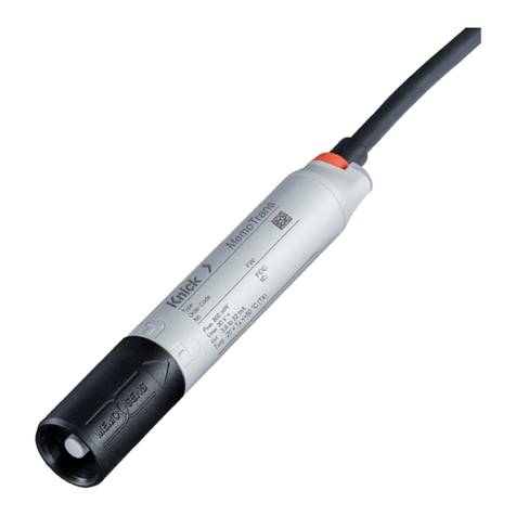
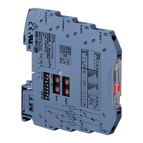
Knick MemoTrans MT 201N User manual

The Art of Measuring.
Aktuelle Produktinformationen:
Latest Product Information:
Informations produit actualisées:
www.knick.de
Deutsch 3
GN/YE
GN/YE
MemoTrans® MT 201N
Installationsanleitung
für Multiparameter-Kompakt-Transmitter
Installation Guide
for Multiparameter Compact Transmitters
Instructions d‘installation
pour transmetteurs multiparamètres compacts
English 13
Français 23
Diese Installationsanleitung ersetzt nicht die vollständige Betriebsanleitung auf:
This Installation Guide does not substitute the complete manual on:
Cettes instructions d'installations ne remplacent pas les instructions complètes sur:
www.knick.de

3
Inhaltsverzeichnis
1 Hinweise zum Dokument .............................................................................. 4
1.1 Warnhinweise ................................................................................................................................................................... 4
1.2 Symbole .............................................................................................................................................................................. 4
1.3 Symbole am Gerät ........................................................................................................................................................... 4
2Grundlegende Sicherheitshinweise ........................................................... 5
2.1 Anforderungen an das Personal ................................................................................................................................ 5
2.2 Bestimmungsgemäße Verwendung ........................................................................................................................ 5
2.3 Arbeitssicherheit .............................................................................................................................................................. 5
2.4 Betriebssicherheit ............................................................................................................................................................ 5
2.5 Produktsicherheit ............................................................................................................................................................ 6
3Produktbeschreibung ................................................................................. 7
3.1 Produktaufbau ................................................................................................................................................................. 7
4Warenannahme und Produktidentifizierung ........................................... 7
4.1 Warenannahme ............................................................................................................................................................... 7
4.2 Produktidentifizierung .................................................................................................................................................. 8
5Elektrischer Anschluss ................................................................................ 8
5.1 Umgebungsbedingungen ........................................................................................................................................... 9
6Systemintegration ...................................................................................... 10
6.1 Messgerät im System einbinden ............................................................................................................................... 10
7Inbetriebnahme .......................................................................................... 11
7.1 Installations- und Funktionskontrolle ..................................................................................................................... 11

4
1
1.1
Hinweise zum Dokument
Warnhinweise
Struktur des Hinweises Bedeutung
WARNUNG
Ursache (/Folgen)
Ggf. Folgen der Missachtung
‣Maßnahme zur Abwehr
Dieser Hinweis macht Sie auf eine gefährliche Situation aufmerksam. Wenn Sie
die gefährliche Situation nicht vermeiden, kann dies zum Tod oder zu
schweren Verletzungen führen.
VORSICHT
Ursache (/Folgen)
Ggf. Folgen der Missachtung
‣Maßnahme zur Abwehr
Dieser Hinweis macht Sie auf eine gefährliche Situation aufmerksam.
Wenn Sie die gefährliche Situation nicht vermeiden, kann dies zu
mittelschweren oder leichten Verletzungen führen.
HINWEIS
Ursache/Situation
Ggf. Folgen der Missachtung
‣Maßnahme/Hinweis
Dieser Hinweis macht Sie auf Situationen aufmerksam, die zu Sachschäden
führen können.
1.2 Symbole
Symbol Bedeutung
Zusatzinformationen, Tipp
erlaubt oder empfohlen
verboten oder nicht empfohlen
Verweis auf Dokumentation zum Gerät
Verweis auf Seite
Verweis auf Abbildung
Ergebnis eines Handlungsschritts
1.3 Symbole am Gerät
Symbol Bedeutung
Verweis auf Dokumentation zum Gerät
5
2
2.1
Grundlegende Sicherheitshinweise
Anforderungen an das Personal
•Montage, Inbetriebnahme, Bedienung und Wartung der Messeinrichtung dürfen nur durch
dafür ausgebildetes Fachpersonal erfolgen.
•Das Fachpersonal muss vom Anlagenbetreiber für die genannten Tätigkeiten autorisiert sein.
•Der elektrische Anschluss darf nur durch eine Elektrofachkraft erfolgen.
•Das Fachpersonal muss diese Betriebsanleitung gelesen und verstanden haben und die
Anweisungen dieser Betriebsanleitung befolgen.
•Störungen an der Messstelle dürfen nur von autorisiertem und dafür ausgebildetem Personal
behoben werden.
Reparaturen, die nicht in der mitgelieferten Betriebsanleitung beschrieben sind, dürfen
nur direkt beim Hersteller oder durch die Serviceorganisation durchgeführt werden.
2.2 Bestimmungsgemäße Verwendung
Das Gerät ist ein Messumformer zum Anschluss digitaler Sensoren mit
Memosens-Technologie, konfigurierbar, mit 4..20 mA/HART Kommunikation und optionaler
Bedienung per Smartphone oder anderen mobilen Geräten über Bluetooth.
Das Gerät ist für den Einsatz in folgenden Industrien bestimmt:
•Life Science
•Chemie
•Wasser und Abwasser
•Lebensmittel und Getränke
•Kraftwerke
•Weitere industrielle Anwendungen
2.3 Arbeitssicherheit
Als Anwender sind Sie für die Einhaltung folgender Sicherheitsbestimmungen verantwortlich:
•Installationsvorschriften
•Lokale Normen und Vorschriften
•Vorschriften zum Explosionsschutz
Störsicherheit
•Das Produkt ist gemäß den gültigen europäischen Normen für den Industriebereich auf
elektromagnetische Verträglichkeit geprüft.
•Die angegebene Störsicherheit gilt nur für ein Produkt, das gemäß den Anweisungen in
dieser Betriebsanleitung angeschlossen ist.
2.4 Betriebssicherheit
Vor der Inbetriebnahme der Gesamtmessstelle:
1. Alle Anschlüsse auf ihre Richtigkeit prüfen.
2. Sicherstellen, dass elektrische Kabel und Schlauchverbindungen nicht beschädigt sind.

6
3. Beschädigte Produkte nicht in Betrieb nehmen und vor versehentlicher Inbetriebnahme
schützen.
4. Beschädigte Produkte als defekt kennzeichnen.
Im Betrieb:
‣Können Störungen nicht behoben werden:
Produkte außer Betrieb setzen und vor versehentlicher Inbetriebnahme schützen.
VORSICHT
‣Eine angeschlossene Reinigung ausschalten, bevor Sie einen Sensor aus dem Medium
nehmen.
‣Sich durch Schutzkleidung, -brille und -handschuhe oder andere geeignete Maßnahmen
schützen, wenn Sie die Reinigungsfunktion prüfen wollen und deshalb die Reinigung nicht
ausschalten.
2.5
2.5.1
Produktsicherheit
Stand der Technik
Das Produkt ist nach dem Stand der Technik betriebssicher gebaut, geprüft und hat das Werk in
sicherheitstechnisch einwandfreiem Zustand verlassen. Die einschlägigen Vorschriften
und europäischen Normen sind berücksichtigt.
Verletzungsgefahr durch Medium oder Reiniger!
Nicht abgeschaltete Reinigung während Kalibrierung oder Wartung
7
3
3.1
Produktbeschreibung
Produktaufbau
1
2
3
4
A0036216
1
1
2
3
4
Aufbau Messumformer
Kabel
Gehäuse
Memosensanschluss
Leuchtdiode, zur optischen Signalisierung von Betriebszuständen der Messstelle
3.1.1 Messparameter
Der Messumformer ist ausgelegt für digitale Memosens Sensoren mit induktivem Steckkopf:
•pH, Redox. pH/Redox-Kombisensoren
•Leitfähigkeit
•Gelöster Sauerstoff
4
4.1
Warenannahme und Produktidentifizierung
Warenannahme
1. Auf unbeschädigte Verpackung achten.
Beschädigungen an der Verpackung dem Lieferanten mitteilen.
Beschädigte Verpackung bis zur Klärung aufbewahren.
2. Auf unbeschädigten Inhalt achten.
Beschädigungen am Lieferinhalt dem Lieferanten mitteilen.
Beschädigte Ware bis zur Klärung aufbewahren.
3. Lieferung auf Vollständigkeit prüfen.
Lieferpapiere und Bestellung vergleichen.

8
4. Für Lagerung und Transport: Produkt stoßsicher und gegen Feuchtigkeit geschützt
verpacken.
Optimalen Schutz bietet die Originalverpackung.
Zulässige Umgebungsbedingungen unbedingt einhalten. Bei
Rückfragen: An Lieferanten oder Vertriebszentrale wenden.
4.2
4.2.1
Produktidentifizierung
Typenschild
Folgende Informationen zu Ihrem Gerät können Sie dem Typenschild entnehmen:
•Herstelleridentifikation
•Seriennummer
•Sicherheits- und Warnhinweise
•Ex-Kennzeichnung bei Ex-Ausführungen
•Zertifikatsinformationen
‣Vergleichen Sie die Angaben auf dem Typenschild mit Ihrer Bestellung.
4.2.2 Produkt identifizieren
Lieferumfang
Im Lieferumfang sind:
•Kompaktes 2-Leiter-Multiparameter-Gerät
•Kurzanleitung
‣Bei Rückfragen:
An Ihren Lieferanten oder an Ihre Vertriebszentrale wenden.
5 Elektrischer Anschluss
WARNUNG
Gerät unter Spannung!
Unsachgemäßer Anschluss kann zu Verletzungen oder Tod führen!
‣Der elektrische Anschluss darf nur von einer Elektrofachkraft durchgeführt werden.
‣Die Elektrofachkraft muss diese Betriebsanleitung gelesen und verstanden haben und muss
die Anweisungen dieser Anleitung befolgen.
‣Vor Beginn der Anschlussarbeiten sicherstellen, dass an keinem Kabel Spannung anliegt.
Versorgungsspannung: 12,6 ... 30 VDC (Bei einem Fehlerstrom > 20 mA)
14 ... 30 VDC (Wenn der Fehlerstrom bei 3,6 mA eingestellt ist.)
Kabellänge: 3 m (10 ft)
7 m (23 ft)
15 m (46 ft)
9
Signalausgang: 4 ... 20 mA/HART
Ausfallsignal: 3,6 ... 23 mA
BU
WH
+
–
A0033282
2 Elektrischer Anschluss
‣Aderendhülsen anschließen, wie in der Tabelle angegeben:
Kabel Funktion
Blau (BU) 4 .... 20 mA +
Weiß (WH) 4 .... 20 mA -
Das Erdungskabel muss vom Anwender gestellt werden.
5.1 Umgebungsbedingungen
Verschmutzungsgrad komplettes Gerät: Verschmutzungsgrad 4
Verschmutzungsgrad intern: Verschmutzungsgrad 2
Installationskategorie: Installation Category 1
Max. Höhe: 2000 m (6561.68 ft)
Schutzart: NEMA Type 6
IP 67
IP 68
Umgebungstemperaturbereich: -20°C … 85°C (-4 ... 185 F°)
Lagerungstemperatur: -40 ... +85 °C (-40 ... 185 °F)
Relative Feuchte: 5 ... 95 %
Vorgeschnittenes Isolationsstück vom Schirmgeecht abziehen und das Geecht in
geeigneter Weise erden.
Ein Erdungskabel muss vom Anwender gestellt werden.
8
4. Für Lagerung und Transport: Produkt stoßsicher und gegen Feuchtigkeit geschützt
verpacken.
Optimalen Schutz bietet die Originalverpackung.
Zulässige Umgebungsbedingungen unbedingt einhalten. Bei
Rückfragen: An Lieferanten oder Vertriebszentrale wenden.
4.2
4.2.1
Produktidentifizierung
Typenschild
Folgende Informationen zu Ihrem Gerät können Sie dem Typenschild entnehmen:
•Herstelleridentifikation
•Seriennummer
•Sicherheits- und Warnhinweise
•Ex-Kennzeichnung bei Ex-Ausführungen
•Zertifikatsinformationen
‣Vergleichen Sie die Angaben auf dem Typenschild mit Ihrer Bestellung.
4.2.2 Produkt identifizieren
Lieferumfang
Im Lieferumfang sind:
•Kompaktes 2-Leiter-Multiparameter-Gerät
•Kurzanleitung
‣Bei Rückfragen:
An Ihren Lieferanten oder an Ihre Vertriebszentrale wenden.
5 Elektrischer Anschluss
WARNUNG
Gerät unter Spannung!
Unsachgemäßer Anschluss kann zu Verletzungen oder Tod führen!
‣Der elektrische Anschluss darf nur von einer Elektrofachkraft durchgeführt werden.
‣Die Elektrofachkraft muss diese Betriebsanleitung gelesen und verstanden haben und muss
die Anweisungen dieser Anleitung befolgen.
‣Vor Beginn der Anschlussarbeiten sicherstellen, dass an keinem Kabel Spannung anliegt.
Versorgungsspannung: 12,6 ... 30 VDC (Bei einem Fehlerstrom > 20 mA)
14 ... 30 VDC (Wenn der Fehlerstrom bei 3,6 mA eingestellt ist.)
Kabellänge: 3 m (10 ft)
7 m (23 ft)
15 m (46 ft)
9
Signalausgang: 4 ... 20 mA/HART
Ausfallsignal: 3,6 ... 23 mA
BU
WH
+
–
A0033282
2 Elektrischer Anschluss
‣Aderendhülsen anschließen, wie in der Tabelle angegeben:
Kabel Funktion
Blau (BU) 4 .... 20 mA +
Weiß (WH) 4 .... 20 mA -
Das Erdungskabel muss vom Anwender gestellt werden.
5.1 Umgebungsbedingungen
Verschmutzungsgrad komplettes Gerät: Verschmutzungsgrad 4
Verschmutzungsgrad intern: Verschmutzungsgrad 2
Installationskategorie: Installation Category 1
Max. Höhe: 2000 m (6561.68 ft)
Schutzart: NEMA Type 6
IP 67
IP 68
Umgebungstemperaturbereich: -20°C … 85°C (-4 ... 185 F°)
Lagerungstemperatur: -40 ... +85 °C (-40 ... 185 °F)
Relative Feuchte: 5 ... 95 %
8
4. Für Lagerung und Transport: Produkt stoßsicher und gegen Feuchtigkeit geschützt
verpacken.
Optimalen Schutz bietet die Originalverpackung.
Zulässige Umgebungsbedingungen unbedingt einhalten. Bei
Rückfragen: An Lieferanten oder Vertriebszentrale wenden.
4.2
4.2.1
Produktidentifizierung
Typenschild
Folgende Informationen zu Ihrem Gerät können Sie dem Typenschild entnehmen:
•Herstelleridentifikation
•Seriennummer
•Sicherheits- und Warnhinweise
•Ex-Kennzeichnung bei Ex-Ausführungen
•Zertifikatsinformationen
‣Vergleichen Sie die Angaben auf dem Typenschild mit Ihrer Bestellung.
4.2.2 Produkt identifizieren
Lieferumfang
Im Lieferumfang sind:
•Kompaktes 2-Leiter-Multiparameter-Gerät
•Kurzanleitung
‣Bei Rückfragen:
An Ihren Lieferanten oder an Ihre Vertriebszentrale wenden.
5 Elektrischer Anschluss
WARNUNG
Gerät unter Spannung!
Unsachgemäßer Anschluss kann zu Verletzungen oder Tod führen!
‣Der elektrische Anschluss darf nur von einer Elektrofachkraft durchgeführt werden.
‣Die Elektrofachkraft muss diese Betriebsanleitung gelesen und verstanden haben und muss
die Anweisungen dieser Anleitung befolgen.
‣Vor Beginn der Anschlussarbeiten sicherstellen, dass an keinem Kabel Spannung anliegt.
Versorgungsspannung: 12,6 ... 30 VDC (Bei einem Fehlerstrom > 20 mA)
14 ... 30 VDC (Wenn der Fehlerstrom bei 3,6 mA eingestellt ist.)
Kabellänge: 3 m (10 ft)
7 m (23 ft)
15 m (46 ft)
9
Signalausgang: 4 ... 20 mA/HART
Ausfallsignal: 3,6 ... 23 mA
BU
WH
+
–
A0033282
2 Elektrischer Anschluss
‣
Aderendhülsen anschließen, wie in der Tabelle angegeben:
Kabel Funktion
Blau (BU) 4 .... 20 mA +
Weiß (WH) 4 .... 20 mA -
Das Erdungskabel muss vom Anwender gestellt werden.
5.1 Umgebungsbedingungen
Verschmutzungsgrad komplettes Gerät: Verschmutzungsgrad 4
Verschmutzungsgrad intern: Verschmutzungsgrad 2
Installationskategorie: Installation Category 1
Max. Höhe: 2000 m (6561.68 ft)
Schutzart: NEMA Type 6
IP 67
IP 68
Umgebungstemperaturbereich: -20°C … 85°C (-4 ... 185 F°)
Lagerungstemperatur: -40 ... +85 °C (-40 ... 185 °F)
Relative Feuchte: 5 ... 95 %
8
4. Für Lagerung und Transport: Produkt stoßsicher und gegen Feuchtigkeit geschützt
verpacken.
Optimalen Schutz bietet die Originalverpackung.
Zulässige Umgebungsbedingungen unbedingt einhalten. Bei
Rückfragen: An Lieferanten oder Vertriebszentrale wenden.
4.2
4.2.1
Produktidentifizierung
Typenschild
Folgende Informationen zu Ihrem Gerät können Sie dem Typenschild entnehmen:
•Herstelleridentifikation
•Seriennummer
•Sicherheits- und Warnhinweise
•Ex-Kennzeichnung bei Ex-Ausführungen
•Zertifikatsinformationen
‣Vergleichen Sie die Angaben auf dem Typenschild mit Ihrer Bestellung.
4.2.2 Produkt identifizieren
Lieferumfang
Im Lieferumfang sind:
•Kompaktes 2-Leiter-Multiparameter-Gerät
•Kurzanleitung
‣Bei Rückfragen:
An Ihren Lieferanten oder an Ihre Vertriebszentrale wenden.
5 Elektrischer Anschluss
WARNUNG
Gerät unter Spannung!
Unsachgemäßer Anschluss kann zu Verletzungen oder Tod führen!
‣Der elektrische Anschluss darf nur von einer Elektrofachkraft durchgeführt werden.
‣Die Elektrofachkraft muss diese Betriebsanleitung gelesen und verstanden haben und muss
die Anweisungen dieser Anleitung befolgen.
‣Vor Beginn der Anschlussarbeiten sicherstellen, dass an keinem Kabel Spannung anliegt.
Versorgungsspannung: 12,6 ... 30 VDC (Bei einem Fehlerstrom > 20 mA)
14 ... 30 VDC (Wenn der Fehlerstrom bei 3,6 mA eingestellt ist.)
Kabellänge: 3 m (10 ft)
7 m (23 ft)
15 m (46 ft)
9
Signalausgang: 4 ... 20 mA/HART
Ausfallsignal: 3,6 ... 23 mA
BU
WH
+
–
A0033282
2 Elektrischer Anschluss
‣Aderendhülsen anschließen, wie in der Tabelle angegeben:
Kabel Funktion
Blau (BU) 4 .... 20 mA +
Weiß (WH) 4 .... 20 mA -
Das Erdungskabel muss vom Anwender gestellt werden.
5.1 Umgebungsbedingungen
Verschmutzungsgrad komplettes Gerät: Verschmutzungsgrad 4
Verschmutzungsgrad intern: Verschmutzungsgrad 2
Installationskategorie: Installation Category 1
Max. Höhe: 2000 m (6561.68 ft)
Schutzart: NEMA Type 6
IP 67
IP 68
Umgebungstemperaturbereich: -20°C … 85°C (-4 ... 185 F°)
Lagerungstemperatur: -40 ... +85 °C (-40 ... 185 °F)
Relative Feuchte: 5 ... 95 %
8
4. Für Lagerung und Transport: Produkt stoßsicher und gegen Feuchtigkeit geschützt
verpacken.
Optimalen Schutz bietet die Originalverpackung.
Zulässige Umgebungsbedingungen unbedingt einhalten. Bei
Rückfragen: An Lieferanten oder Vertriebszentrale wenden.
4.2
4.2.1
Produktidentifizierung
Typenschild
Folgende Informationen zu Ihrem Gerät können Sie dem Typenschild entnehmen:
•Herstelleridentifikation
•Seriennummer
•Sicherheits- und Warnhinweise
•Ex-Kennzeichnung bei Ex-Ausführungen
•Zertifikatsinformationen
‣Vergleichen Sie die Angaben auf dem Typenschild mit Ihrer Bestellung.
4.2.2 Produkt identifizieren
Lieferumfang
Im Lieferumfang sind:
•Kompaktes 2-Leiter-Multiparameter-Gerät
•Kurzanleitung
‣Bei Rückfragen:
An Ihren Lieferanten oder an Ihre Vertriebszentrale wenden.
5 Elektrischer Anschluss
WARNUNG
Gerät unter Spannung!
Unsachgemäßer Anschluss kann zu Verletzungen oder Tod führen!
‣Der elektrische Anschluss darf nur von einer Elektrofachkraft durchgeführt werden.
‣Die Elektrofachkraft muss diese Betriebsanleitung gelesen und verstanden haben und muss
die Anweisungen dieser Anleitung befolgen.
‣Vor Beginn der Anschlussarbeiten sicherstellen, dass an keinem Kabel Spannung anliegt.
Versorgungsspannung: 12,6 ... 30 VDC (Bei einem Fehlerstrom > 20 mA)
14 ... 30 VDC (Wenn der Fehlerstrom bei 3,6 mA eingestellt ist.)
Kabellänge: 3 m (10 ft)
7 m (23 ft)
15 m (46 ft)
9
Signalausgang: 4 ... 20 mA/HART
Ausfallsignal: 3,6 ... 23 mA
BU
WH
+
–
A0033282
2 Elektrischer Anschluss
‣Aderendhülsen anschließen, wie in der Tabelle angegeben:
Kabel Funktion
Blau (BU) 4 .... 20 mA +
Weiß (WH) 4 .... 20 mA -
Das Erdungskabel muss vom Anwender gestellt werden.
5.1 Umgebungsbedingungen
Verschmutzungsgrad komplettes Gerät: Verschmutzungsgrad 4
Verschmutzungsgrad intern: Verschmutzungsgrad 2
Installationskategorie: Installation Category 1
Max. Höhe: 2000 m (6561.68 ft)
Schutzart: NEMA Type 6
IP 67
IP 68
Umgebungstemperaturbereich: -20°C … 85°C (-4 ... 185 F°)
Lagerungstemperatur: -40 ... +85 °C (-40 ... 185 °F)
Relative Feuchte: 5 ... 95 %
8
4. Für Lagerung und Transport: Produkt stoßsicher und gegen Feuchtigkeit geschützt
verpacken.
Optimalen Schutz bietet die Originalverpackung.
Zulässige Umgebungsbedingungen unbedingt einhalten. Bei
Rückfragen: An Lieferanten oder Vertriebszentrale wenden.
4.2
4.2.1
Produktidentifizierung
Typenschild
Folgende Informationen zu Ihrem Gerät können Sie dem Typenschild entnehmen:
•Herstelleridentifikation
•Seriennummer
•Sicherheits- und Warnhinweise
•Ex-Kennzeichnung bei Ex-Ausführungen
•Zertifikatsinformationen
‣Vergleichen Sie die Angaben auf dem Typenschild mit Ihrer Bestellung.
4.2.2 Produkt identifizieren
Lieferumfang
Im Lieferumfang sind:
•Kompaktes 2-Leiter-Multiparameter-Gerät
•Kurzanleitung
‣Bei Rückfragen:
An Ihren Lieferanten oder an Ihre Vertriebszentrale wenden.
5 Elektrischer Anschluss
WARNUNG
Gerät unter Spannung!
Unsachgemäßer Anschluss kann zu Verletzungen oder Tod führen!
‣Der elektrische Anschluss darf nur von einer Elektrofachkraft durchgeführt werden.
‣Die Elektrofachkraft muss diese Betriebsanleitung gelesen und verstanden haben und muss
die Anweisungen dieser Anleitung befolgen.
‣Vor Beginn der Anschlussarbeiten sicherstellen, dass an keinem Kabel Spannung anliegt.
Versorgungsspannung: 12,6 ... 30 VDC (Bei einem Fehlerstrom > 20 mA)
14 ... 30 VDC (Wenn der Fehlerstrom bei 3,6 mA eingestellt ist.)
Kabellänge: 3 m (10 ft)
7 m (23 ft)
15 m (46 ft)
9
Signalausgang: 4 ... 20 mA/HART
Ausfallsignal: 3,6 ... 23 mA
BU
WH
+
–
A0033282
2 Elektrischer Anschluss
‣Aderendhülsen anschließen, wie in der Tabelle angegeben:
Kabel Funktion
Blau (BU) 4 .... 20 mA +
Weiß (WH) 4 .... 20 mA -
Das Erdungskabel muss vom Anwender gestellt werden.
5.1 Umgebungsbedingungen
Verschmutzungsgrad komplettes Gerät: Verschmutzungsgrad 4
Verschmutzungsgrad intern: Verschmutzungsgrad 2
Installationskategorie: Installation Category 1
Max. Höhe: 2000 m (6561.68 ft)
Schutzart: NEMA Type 6
IP 67
IP 68
Umgebungstemperaturbereich: -20°C … 85°C (-4 ... 185 F°)
Lagerungstemperatur: -40 ... +85 °C (-40 ... 185 °F)
Relative Feuchte: 5 ... 95 %

10
6
6.1
Systemintegration
Messgerät im System einbinden
für die Messwertübertragung:
•4…20 mA
•Bluetooth® LE wireless technology
•HART
6.1.1 Bluetooth® LE wireless technology
12
A0036075
3 Möglichkeiten der Fernbedienung via Bluetooth® LE wireless technology
1 Smartphone / Tablet mit App
3 Messumformer mit Bluetooth® wireless technology
6.1.2 HART
Über das HART Protokoll können neben dem analogen 4 ... 20 mA Signal weitere Messwerte,
sowie der Status des Geräts digital übertragen werden.
Auch die Parametrierung ist mittels eines zusätzlichen Bediengerätes und einem passenden
Treiber möglich.
Die Bedienung ist über DTM Hosts, sowie diverse Bediengeräte (Handhelds) möglich.
11
ESC
+ E
1
3
4
2
56
A0036740
4
1
2
3
4
5
6
Verdrahtungsmöglichkeiten bei Fernbedienung via HART-Protokoll
SPS (Speicherprogrammierbare Steuerung)
Schleifengespeister Prozessanzeiger, optional
Verteilerdose
HART Bediengerät, optional
Messumformer mit Bluetooth® LE wireless technology
Optional: Smartphone / Tablet mit App
7
7.1
Inbetriebnahme
Installations- und Funktionskontrolle
WARNUNG
Falscher Anschluss, falsche Versorgungsspannung
Sicherheitsrisiken für Personal und Fehlfunktionen des Gerätes!
‣Kontrollieren, dass alle Anschlüsse entsprechend Anschlussplan korrekt ausgeführt sind.
‣Sicherstellen, dass die Versorgungsspannung mit der auf dem Typenschild angegebenen
Spannung übereinstimmt.
Machen Sie sich vor dem ersten Einschalten mit der Bedienung des Geräts vertraut. Lesen Sie
dazu besonders die Kapitel "Grundlegende Sicherheitshinweise". Nach dem Einschalten
durchläuft das Gerät einen Selbsttest und geht anschließend in den Mess-Modus.
10
6
6.1
Systemintegration
Messgerät im System einbinden
für die Messwertübertragung:
•4…20 mA
•Bluetooth® LE wireless technology
•HART
6.1.1 Bluetooth® LE wireless technology
12
A0036075
3Möglichkeiten der Fernbedienung via Bluetooth® LE wireless technology
1 Smartphone / Tablet mit App
3 Messumformer mit Bluetooth® wireless technology
6.1.2 HART
Über das HART Protokoll können neben dem analogen 4 ... 20 mA Signal weitere Messwerte,
sowie der Status des Geräts digital übertragen werden.
Auch die Parametrierung ist mittels eines zusätzlichen Bediengerätes und einem passenden
Treiber möglich.
Die Bedienung ist über DTM Hosts, sowie diverse Bediengeräte (Handhelds) möglich.
11
ESC
+ E
1
3
4
2
56
A0036740
4
1
2
3
4
5
6
Verdrahtungsmöglichkeiten bei Fernbedienung via HART-Protokoll
SPS (Speicherprogrammierbare Steuerung)
Schleifengespeister Prozessanzeiger, optional
Verteilerdose
HART Bediengerät, optional
Messumformer mit Bluetooth® LE wireless technology
Optional: Smartphone / Tablet mit App
7
7.1
Inbetriebnahme
Installations- und Funktionskontrolle
WARNUNG
Falscher Anschluss, falsche Versorgungsspannung
Sicherheitsrisiken für Personal und Fehlfunktionen des Gerätes!
‣Kontrollieren, dass alle Anschlüsse entsprechend Anschlussplan korrekt ausgeführt sind.
‣Sicherstellen, dass die Versorgungsspannung mit der auf dem Typenschild angegebenen
Spannung übereinstimmt.
Machen Sie sich vor dem ersten Einschalten mit der Bedienung des Geräts vertraut. Lesen Sie
dazu besonders die Kapitel "Grundlegende Sicherheitshinweise". Nach dem Einschalten
durchläuft das Gerät einen Selbsttest und geht anschließend in den Mess-Modus.

10
6
6.1
Systemintegration
Messgerät im System einbinden
für die Messwertübertragung:
•4…20 mA
•Bluetooth® LE wireless technology
•HART
6.1.1 Bluetooth® LE wireless technology
12
A0036075
3 Möglichkeiten der Fernbedienung via Bluetooth® LE wireless technology
1 Smartphone / Tablet mit App
3 Messumformer mit Bluetooth® wireless technology
6.1.2 HART
Über das HART Protokoll können neben dem analogen 4 ... 20 mA Signal weitere Messwerte,
sowie der Status des Geräts digital übertragen werden.
Auch die Parametrierung ist mittels eines zusätzlichen Bediengerätes und einem passenden
Treiber möglich.
Die Bedienung ist über DTM Hosts, sowie diverse Bediengeräte (Handhelds) möglich.
11
ESC
+ E
1
3
4
2
56
A0036740
4
1
2
3
4
5
6
Verdrahtungsmöglichkeiten bei Fernbedienung via HART-Protokoll
SPS (Speicherprogrammierbare Steuerung)
Schleifengespeister Prozessanzeiger, optional
Verteilerdose
HART Bediengerät, optional
Messumformer mit Bluetooth® LE wireless technology
Optional: Smartphone / Tablet mit App
7
7.1
Inbetriebnahme
Installations- und Funktionskontrolle
WARNUNG
Falscher Anschluss, falsche Versorgungsspannung
Sicherheitsrisiken für Personal und Fehlfunktionen des Gerätes!
‣Kontrollieren, dass alle Anschlüsse entsprechend Anschlussplan korrekt ausgeführt sind.
‣Sicherstellen, dass die Versorgungsspannung mit der auf dem Typenschild angegebenen
Spannung übereinstimmt.
Machen Sie sich vor dem ersten Einschalten mit der Bedienung des Geräts vertraut. Lesen Sie
dazu besonders die Kapitel "Grundlegende Sicherheitshinweise". Nach dem Einschalten
durchläuft das Gerät einen Selbsttest und geht anschließend in den Mess-Modus.
10
6
6.1
Systemintegration
Messgerät im System einbinden
für die Messwertübertragung:
•4…20 mA
•Bluetooth® LE wireless technology
•HART
6.1.1 Bluetooth® LE wireless technology
12
A0036075
3Möglichkeiten der Fernbedienung via Bluetooth® LE wireless technology
1 Smartphone / Tablet mit App
3 Messumformer mit Bluetooth® wireless technology
6.1.2 HART
Über das HART Protokoll können neben dem analogen 4 ... 20 mA Signal weitere Messwerte,
sowie der Status des Geräts digital übertragen werden.
Auch die Parametrierung ist mittels eines zusätzlichen Bediengerätes und einem passenden
Treiber möglich.
Die Bedienung ist über DTM Hosts, sowie diverse Bediengeräte (Handhelds) möglich.
11
ESC
+ E
1
3
4
2
56
A0036740
4
1
2
3
4
5
6
Verdrahtungsmöglichkeiten bei Fernbedienung via HART-Protokoll
SPS (Speicherprogrammierbare Steuerung)
Schleifengespeister Prozessanzeiger, optional
Verteilerdose
HART Bediengerät, optional
Messumformer mit Bluetooth® LE wireless technology
Optional: Smartphone / Tablet mit App
7
7.1
Inbetriebnahme
Installations- und Funktionskontrolle
WARNUNG
Falscher Anschluss, falsche Versorgungsspannung
Sicherheitsrisiken für Personal und Fehlfunktionen des Gerätes!
‣Kontrollieren, dass alle Anschlüsse entsprechend Anschlussplan korrekt ausgeführt sind.
‣Sicherstellen, dass die Versorgungsspannung mit der auf dem Typenschild angegebenen
Spannung übereinstimmt.
Machen Sie sich vor dem ersten Einschalten mit der Bedienung des Geräts vertraut. Lesen Sie
dazu besonders die Kapitel "Grundlegende Sicherheitshinweise". Nach dem Einschalten
durchläuft das Gerät einen Selbsttest und geht anschließend in den Mess-Modus.

12
7.1.1 Gerät einschalten
Sobald das Gerät mit der korrekten Versorgungsspannung verbunden ist, startet es und ist
betriebsbereit. Die LED-Anzeige zeigt den Status an.
Für die Bedienung über die App muss das Bluetooth® LE Signal im Smartphone oder Tablet
eingeschalten sein.
1. App downloaden und installieren.
2. App starten.
3. Gerät aus angezeigter Livelist auswählen. Es werden alle verfügbaren Geräte angezeigt.
4. Login durchführen.
5. Benutzername eingeben -> admin
6. Initial Passwort eingeben -> Geräte-Seriennummer
7. Nach dem ersten Login empfiehlt es sich, den Benutzernamen und das Passwort zu
ändern.
7.1.2 LED Anzeige
LED-Meldungen signalisieren Gerät- und Sensor-Status.
LED Verhalten Status
Grün
Schnelles Blinken
Alles in Ordnung
Gerät startet.
Grün
Zweifaches Blinken
Alles in Ordnung
Memosens Sensorinformation aus Sensor in den Messumformer auslesen (Sensortyp,
Kalibrierdaten etc.)
Grün
Langsames Blinken
Alles in Ordnung
Sensor und Gerät OK und arbeiten ordnungsgemäß.
Grün
Schnelles dreifaches
Blinken
Alles in Ordnung
Messwert an SPS in Automatik HOLD.
Wenn die "Sensorwechselalarmverzögerung" überschritten wird, überträgt das Gerät ein
Ausfallsignal.
Das automatische Hold ist auf 30 Sekunden eingestellt, kann jedoch kundenspezifisch
konfiguriert werden.
Rot
Schnelles Blinken
Ausfall von Gerät oder Sensor
Fehlerzustand nach NAMUR NE107
Rot, Grün
Abwechseln dreifach rot,
dreifach grün
Squawk
Squawk wird beim Verbindungsaufbau kurz signalisiert. Über die App kann ebenfalls Squawk
ativiert werden. Damit lässt sich das Gerät schneller auffinden, z. B. wenn mehrere Geräte
verbaut sind, sieht man, mit welchem die Verbindung hergestellt ist.
13
Table of contents
1 Document information
1.1 Warnings
1.2 Symbols
1.3 Symbols on the device
2 Basic safety instructions
2.1 Requirements for personnel
2.2 Designated use
2.3 Workplace safety
2.4 Operational safety
2.5 Product safety
3 Product description
3.1
4 Incoming acceptance and product identification
4.1 Incoming acceptance
4.2 Product identification
5 Electrical connection
5.1 Environment
6 System integration
6.1 Integrating the measuring device into the system
7 Commissioning
7.1 Function check
................................................................................................. 14
................................................................................................................................................................... 14
. . . . . . . . . . . . . . . . . . . . . . . . . . . . . . . . . . . . . . . . . . . . . . . . . . . . . . . . . . . . . . . . . . . . . . . . . ......................................................................................... . 14
. . . . . . . . . . . . . . . . . . . . . . . . . . . . . . . . . . . . . . . . . . . . . . . . . . . . . . . . . . . ............................................................................. . . . . . . 15
................................................................................................ 15
.................................................................................................................................... 15
. . . . . . . . . . . . . . . . . . . . . . . . . . . . . . . . . . . . . . . . . . . . . . . . . . . . . . . . . . . . . . . . ................................................................................... . . . . . . 15
....................................................................................................................................................... 15
..................................................................................................................................................... 16
............................................................................................................................................................ 16
....... ................................................................................................. 17
Product design ......................................................................................................................................................... 17
........................................................17
. . . . . . . . . . . . . . . . ............................................................................................................................ . . 17
.............................................................................................................................................. 18
...................................................................................................... 18
.............................................................................................................................................................. 19
......................................................................................................... 20
.................................................................................................... 20
................................................................................................................ 21
........................................................................................................................................................... 21
12
7.1.1 Gerät einschalten
Sobald das Gerät mit der korrekten Versorgungsspannung verbunden ist, startet es und ist
betriebsbereit. Die LED-Anzeige zeigt den Status an.
Für die Bedienung über die App muss das Bluetooth® LE Signal im Smartphone oder Tablet
eingeschalten sein.
1. App downloaden und installieren.
2. App starten.
3. Gerät aus angezeigter Livelist auswählen. Es werden alle verfügbaren Geräte angezeigt.
4. Login durchführen.
5. Benutzername eingeben -> admin
6. Initial Passwort eingeben -> Geräte-Seriennummer
7. Nach dem ersten Login empfiehlt es sich, den Benutzernamen und das Passwort zu
ändern.
7.1.2 LED Anzeige
LED-Meldungen signalisieren Gerät- und Sensor-Status.
LED Verhalten Status
Grün
Schnelles Blinken
Alles in Ordnung
Gerät startet.
Grün
Zweifaches Blinken
Alles in Ordnung
Memosens Sensorinformation aus Sensor in den Messumformer auslesen (Sensortyp,
Kalibrierdaten etc.)
Grün
Langsames Blinken
Alles in Ordnung
Sensor und Gerät OK und arbeiten ordnungsgemäß.
Grün
Schnelles dreifaches
Blinken
Alles in Ordnung
Messwert an SPS in Automatik HOLD.
Wenn die "Sensorwechselalarmverzögerung" überschritten wird, überträgt das Gerät ein
Ausfallsignal.
Das automatische Hold ist auf 30 Sekunden eingestellt, kann jedoch kundenspezifisch
konfiguriert werden.
Rot
Schnelles Blinken
Ausfall von Gerät oder Sensor
Fehlerzustand nach NAMUR NE107
Rot, Grün
Abwechseln dreifach rot,
dreifach grün
Squawk
Squawk wird beim Verbindungsaufbau kurz signalisiert. Über die App kann ebenfalls Squawk
ativiert werden. Damit lässt sich das Gerät schneller auffinden, z. B. wenn mehrere Geräte
verbaut sind, sieht man, mit welchem die Verbindung hergestellt ist.
13
Table of contents
1 Document information
1.1 Warnings
1.2 Symbols
1.3 Symbols on the device
2 Basic safety instructions
2.1 Requirements for personnel
2.2 Designated use
2.3 Workplace safety
2.4 Operational safety
2.5 Product safety
3 Product description
3.1
4 Incoming acceptance and product identification
4.1 Incoming acceptance
4.2 Product identification
5 Electrical connection
5.1 Environment
6 System integration
6.1 Integrating the measuring device into the system
7 Commissioning
7.1 Function check
.................................................................................................. 14
................................................................................................................................................................... 14
. . . . . . . . . . . . . . . . . . . . . . . . . . . . . . . . . . . . . . . . . . . . . . . . . . . . . . . . . . . . . . . . . . . . . . . . . ......................................................................................... . 14
. . . . . . . . . . . . . . . . . . . . . . . . . . . . . . . . . . . . . . . . . . . . . . . . . . . . . . . . . . . ............................................................................. . . . . . . 15
................................................................................................ 15
.................................................................................................................................... 15
. . . . . . . . . . . . . . . . . . . . . . . . . . . . . . . . . . . . . . . . . . . . . . . . . . . . . . . . . . . . . . . . ................................................................................... . . . . . . 15
....................................................................................................................................................... 15
..................................................................................................................................................... 16
............................................................................................................................................................ 16
....... ................................................................................................. 17
Product design ......................................................................................................................................................... 17
.........................................................17
. . . . . . . . . . . . . . . . ............................................................................................................................ . . 17
.............................................................................................................................................. 18
...................................................................................................... 18
.............................................................................................................................................................. 19
......................................................................................................... 20
.................................................................................................... 20
................................................................................................................ 21
........................................................................................................................................................... 21

12
7.1.1 Gerät einschalten
Sobald das Gerät mit der korrekten Versorgungsspannung verbunden ist, startet es und ist
betriebsbereit. Die LED-Anzeige zeigt den Status an.
Für die Bedienung über die App muss das Bluetooth® LE Signal im Smartphone oder Tablet
eingeschalten sein.
1. App downloaden und installieren.
2. App starten.
3. Gerät aus angezeigter Livelist auswählen. Es werden alle verfügbaren Geräte angezeigt.
4. Login durchführen.
5. Benutzername eingeben -> admin
6. Initial Passwort eingeben -> Geräte-Seriennummer
7. Nach dem ersten Login empfiehlt es sich, den Benutzernamen und das Passwort zu
ändern.
7.1.2 LED Anzeige
LED-Meldungen signalisieren Gerät- und Sensor-Status.
LED Verhalten Status
Grün
Schnelles Blinken
Alles in Ordnung
Gerät startet.
Grün
Zweifaches Blinken
Alles in Ordnung
Memosens Sensorinformation aus Sensor in den Messumformer auslesen (Sensortyp,
Kalibrierdaten etc.)
Grün
Langsames Blinken
Alles in Ordnung
Sensor und Gerät OK und arbeiten ordnungsgemäß.
Grün
Schnelles dreifaches
Blinken
Alles in Ordnung
Messwert an SPS in Automatik HOLD.
Wenn die "Sensorwechselalarmverzögerung" überschritten wird, überträgt das Gerät ein
Ausfallsignal.
Das automatische Hold ist auf 30 Sekunden eingestellt, kann jedoch kundenspezifisch
konfiguriert werden.
Rot
Schnelles Blinken
Ausfall von Gerät oder Sensor
Fehlerzustand nach NAMUR NE107
Rot, Grün
Abwechseln dreifach rot,
dreifach grün
Squawk
Squawk wird beim Verbindungsaufbau kurz signalisiert. Über die App kann ebenfalls Squawk
ativiert werden. Damit lässt sich das Gerät schneller auffinden, z. B. wenn mehrere Geräte
verbaut sind, sieht man, mit welchem die Verbindung hergestellt ist.
13
Table of contents
1 Document information
1.1 Warnings
1.2 Symbols
1.3 Symbols on the device
2 Basic safety instructions
2.1 Requirements for personnel
2.2 Designated use
2.3 Workplace safety
2.4 Operational safety
2.5 Product safety
3 Product description
3.1
4 Incoming acceptance and product identification
4.1 Incoming acceptance
4.2 Product identification
5 Electrical connection
5.1 Environment
6 System integration
6.1 Integrating the measuring device into the system
7 Commissioning
7.1 Function check
................................................................................................. 14
................................................................................................................................................................... 14
. . . . . . . . . . . . . . . . . . . . . . . . . . . . . . . . . . . . . . . . . . . . . . . . . . . . . . . . . . . . . . . . . . . . . . . . . ......................................................................................... . 14
. . . . . . . . . . . . . . . . . . . . . . . . . . . . . . . . . . . . . . . . . . . . . . . . . . . . . . . . . . . ............................................................................. . . . . . . 15
................................................................................................ 15
.................................................................................................................................... 15
. . . . . . . . . . . . . . . . . . . . . . . . . . . . . . . . . . . . . . . . . . . . . . . . . . . . . . . . . . . . . . . . ................................................................................... . . . . . . 15
....................................................................................................................................................... 15
..................................................................................................................................................... 16
............................................................................................................................................................ 16
....... ................................................................................................. 17
Product design ......................................................................................................................................................... 17
........................................................17
. . . . . . . . . . . . . . . . ............................................................................................................................ . . 17
.............................................................................................................................................. 18
...................................................................................................... 18
.............................................................................................................................................................. 19
......................................................................................................... 20
.................................................................................................... 20
................................................................................................................ 21
........................................................................................................................................................... 21
12
7.1.1 Gerät einschalten
Sobald das Gerät mit der korrekten Versorgungsspannung verbunden ist, startet es und ist
betriebsbereit. Die LED-Anzeige zeigt den Status an.
Für die Bedienung über die App muss das Bluetooth® LE Signal im Smartphone oder Tablet
eingeschalten sein.
1. App downloaden und installieren.
2. App starten.
3. Gerät aus angezeigter Livelist auswählen. Es werden alle verfügbaren Geräte angezeigt.
4. Login durchführen.
5. Benutzername eingeben -> admin
6. Initial Passwort eingeben -> Geräte-Seriennummer
7. Nach dem ersten Login empfiehlt es sich, den Benutzernamen und das Passwort zu
ändern.
7.1.2 LED Anzeige
LED-Meldungen signalisieren Gerät- und Sensor-Status.
LED Verhalten Status
Grün
Schnelles Blinken
Alles in Ordnung
Gerät startet.
Grün
Zweifaches Blinken
Alles in Ordnung
Memosens Sensorinformation aus Sensor in den Messumformer auslesen (Sensortyp,
Kalibrierdaten etc.)
Grün
Langsames Blinken
Alles in Ordnung
Sensor und Gerät OK und arbeiten ordnungsgemäß.
Grün
Schnelles dreifaches
Blinken
Alles in Ordnung
Messwert an SPS in Automatik HOLD.
Wenn die "Sensorwechselalarmverzögerung" überschritten wird, überträgt das Gerät ein
Ausfallsignal.
Das automatische Hold ist auf 30 Sekunden eingestellt, kann jedoch kundenspezifisch
konfiguriert werden.
Rot
Schnelles Blinken
Ausfall von Gerät oder Sensor
Fehlerzustand nach NAMUR NE107
Rot, Grün
Abwechseln dreifach rot,
dreifach grün
Squawk
Squawk wird beim Verbindungsaufbau kurz signalisiert. Über die App kann ebenfalls Squawk
ativiert werden. Damit lässt sich das Gerät schneller auffinden, z. B. wenn mehrere Geräte
verbaut sind, sieht man, mit welchem die Verbindung hergestellt ist.
13
Table of contents
1 Document information
1.1 Warnings
1.2 Symbols
1.3 Symbols on the device
2 Basic safety instructions
2.1 Requirements for personnel
2.2 Designated use
2.3 Workplace safety
2.4 Operational safety
2.5 Product safety
3 Product description
3.1
4 Incoming acceptance and product identification
4.1 Incoming acceptance
4.2 Product identification
5 Electrical connection
5.1 Environment
6 System integration
6.1 Integrating the measuring device into the system
7 Commissioning
7.1 Function check
.................................................................................................. 14
................................................................................................................................................................... 14
. . . . . . . . . . . . . . . . . . . . . . . . . . . . . . . . . . . . . . . . . . . . . . . . . . . . . . . . . . . . . . . . . . . . . . . . . ......................................................................................... .
14
. . . . . . . . . . . . . . . . . . . . . . . . . . . . . . . . . . . . . . . . . . . . . . . . . . . . . . . . . . . ............................................................................. . . . . . .
15
................................................................................................ 15
.................................................................................................................................... 15
. . . . . . . . . . . . . . . . . . . . . . . . . . . . . . . . . . . . . . . . . . . . . . . . . . . . . . . . . . . . . . . . ................................................................................... . . . . . .
15
....................................................................................................................................................... 15
..................................................................................................................................................... 16
............................................................................................................................................................ 16
....... ................................................................................................. 17
Product design ......................................................................................................................................................... 17
.........................................................17
. . . . . . . . . . . . . . . . ............................................................................................................................ . . 17
.............................................................................................................................................. 18
...................................................................................................... 18
.............................................................................................................................................................. 19
......................................................................................................... 20
.................................................................................................... 20
................................................................................................................ 21
........................................................................................................................................................... 21

14
1
1.1
Document information
Warnings
Structure of information Meaning
WARNING
Causes (/consequences)
If necessary, Consequences of non-
compliance (if applicable)
‣Corrective action
This symbol alerts you to a dangerous situation.
Failure to avoid the dangerous situation can result in a fatal or serious injury.
CAUTION
Causes (/consequences)
If necessary, Consequences of non-
compliance (if applicable)
‣Corrective action
This symbol alerts you to a dangerous situation.
Failure to avoid this situation can result in minor or more serious injuries.
NOTICE
Cause/situation
If necessary, Consequences of non-
compliance (if applicable)
‣Action/note
This symbol alerts you to situations which may result in damage to property.
1.2 Symbols
Symbol Meaning
Additional information, tips
Permitted or recommended
Not permitted or not recommended
Reference to device documentation
Reference to page
Reference to graphic
Result of a step
15
1.3 Symbols on the device
Symbol Meaning
Reference to device documentation
2
2.1
Basic safety instructions
Requirements for personnel
•Installation, commissioning, operation and maintenance of the measuring system may be
carried out only by specially trained technical personnel.
•The technical personnel must be authorized by the plant operator to carry out the specified
activities.
•The electrical connection may be performed only by an electrical technician.
•The technical personnel must have read and understood these Operating Instructions and
must follow the instructions contained therein.
•Faults at the measuring point may only be rectified by authorized and specially trained
personnel.
Repairs not described in the Operating Instructions provided must be carried out only
directly at the manufacturer's site or by the service organization.
2.2 Designated use
The device is a transmitter for connecting digital sensors with Memosens technology,
configurable, with 4..20 mA/HART communication and optional operation via smartphone or
other mobile devices via Bluetooth.
The device is designed for use in the following industries:
•Life science
•Chemical industry
•Water and wastewater
•Food and beverages
•Power stations
•Other industrial applications
2.3 Workplace safety
As the user, you are responsible for complying with the following safety conditions:
•Installation guidelines
•Local standards and regulations
•Regulations for explosion protection

16
Electromagnetic compatibility
•The product has been tested for electromagnetic compatibility in accordance with the
applicable European standards for industrial applications.
•The electromagnetic compatibility indicated applies only to a product that has been
connected in accordance with these Operating Instructions.
2.4 Operational safety
Before commissioning the entire measuring point:
1. Verify that all connections are correct.
2. Ensure that electrical cables and hose connections are undamaged.
3. Do not operate damaged products, and protect them against unintentional operation.
4. Label damaged products as defective.
During operation:
‣If faults cannot be rectified:
products must be taken out of service and protected against unintentional operation.
CAUTION
Cleaning not switched off during calibration or maintenance activities
Risk of injury due to medium or cleaning agent!
‣If a cleaning system is connected, switch it off before removing a sensor from the medium.
‣If you wish to check the cleaning function and have therefore not switched off the cleaning
system, wear protective clothing, goggles and gloves or take other appropriate measures.
2.5
2.5.1
Product safety
State of the art
The product is designed to meet state-of-the-art safety requirements, has been tested, and
left the factory in a condition in which it is safe to operate. The relevant regulations and
European standards have been observed.
17
3
3.1
Product description
Product design
1
2
3
4
A0036216
1
1
2
3
4
Transmitter design
Cable
Housing
Memosens connection
LED, for optical signaling of operating statuses of measuring point
3.1.1 Measuring parameters
The transmitter is designed for digital Memosens sensors with inductive plug-in head:
•pH, ORP, pH/ORP combined sensors
•Conductivity
•Dissolved oxygen
4
4.1
Incoming acceptance and product identification
Incoming acceptance
1. Verify that the packaging is undamaged.
Notify the supplier of any damage to the packaging.
Keep the damaged packaging until the issue has been resolved.
2. Verify that the contents are undamaged.
Notify the supplier of any damage to the delivery contents.
Keep the damaged goods until the issue has been resolved.
3. Check that the delivery is complete and nothing is missing.
Compare the shipping documents with your order.

18
4. Pack the product for storage and transportation in such a way that it is protected
against impact and moisture.
The original packaging offers the best protection.
Make sure to comply with the permitted ambient conditions.
If you have any questions, please contact your supplier or your local Sales Center.
4.2
4.2.1
Product identification
Nameplate
The nameplate provides you with the following information on your device:
•Manufacturer identification
•Serial number
•Safety information and warnings
•Ex labeling on hazardous area versions
•Certificate information
‣Compare the data on the nameplate with your order.
4.2.2 Product identification
Scope of delivery
The scope of delivery includes:
•Compact 2-wire multiparameter transmitter
•Brief Operating Instructions
‣If you have any queries:
Please contact your supplier or local sales center.
5 Electrical connection
WARNING
Device is live!
Incorrect connection may result in injury or death!
‣The electrical connection may be performed only by an electrical technician.
‣The electrical technician must have read and understood these Operating Instructions and
must follow the instructions contained therein.
‣Prior to commencing connection work, ensure that no voltage is present on any cable.
Supply voltage: 12,6 to 30 VDC (In the case of a residual current > 20 mA) 14
to 30 VDC (When the fault current is set to 3.6 mA.)
Cable length: 3 m (10 ft)
7 m (23 ft)
15 m (46 ft)
19
Signal output: 4 to 20 mA/HART
Signal on alarm: 3.6 to 23 mA
BU
WH
+
–
A0033282
2Electrical connection
‣Connect ferrules as specified in the table:
Cable Function
BU (blue) 4 to 20 mA +
White (WH) 4 to 20 mA -
The grounding cable must be provided by the customer.
5.1 Environment
Degree of pollution of entire device: Pollution level 4
Degree of internal pollution: Pollution level 2
Installation category: Installation category 1
Max. height: 2000 m (6561.68 ft)
Degree of protection: NEMA Type 6
IP 67
IP 68
Ambient temperature range: -20°C to 85°C (-4 to 185 F°)
Storage temperature: -40 ... +85 °C (-40 ... 185 °F)
Relative humidity: 5 ... 95 %
18
4. Pack the product for storage and transportation in such a way that it is protected
against impact and moisture.
The original packaging offers the best protection.
Make sure to comply with the permitted ambient conditions.
If you have any questions, please contact your supplier or your local Sales Center.
4.2
4.2.1
Product identification
Nameplate
The nameplate provides you with the following information on your device:
•Manufacturer identification
•Serial number
•Safety information and warnings
•Ex labeling on hazardous area versions
•Certificate information
‣Compare the data on the nameplate with your order.
4.2.2 Product identification
Scope of delivery
The scope of delivery includes:
•Compact 2-wire multiparameter transmitter
•Brief Operating Instructions
‣If you have any queries:
Please contact your supplier or local sales center.
5 Electrical connection
WARNING
Device is live!
Incorrect connection may result in injury or death!
‣The electrical connection may be performed only by an electrical technician.
‣The electrical technician must have read and understood these Operating Instructions and
must follow the instructions contained therein.
‣Prior to commencing connection work, ensure that no voltage is present on any cable.
Supply voltage: 12,6 to 30 VDC (In the case of a residual current > 20 mA) 14
to 30 VDC (When the fault current is set to 3.6 mA.)
Cable length: 3 m (10 ft)
7 m (23 ft)
15 m (46 ft)
19
Signal output: 4 to 20 mA/HART
Signal on alarm: 3.6 to 23 mA
BU
WH
+
–
A0033282
2 Electrical connection
‣Connect ferrules as specified in the table:
Cable Function
BU (blue) 4 to 20 mA +
White (WH) 4 to 20 mA -
The grounding cable must be provided by the customer.
5.1 Environment
Degree of pollution of entire device: Pollution level 4
Degree of internal pollution: Pollution level 2
Installation category: Installation category 1
Max. height: 2000 m (6561.68 ft)
Degree of protection: NEMA Type 6
IP 67
IP 68
Ambient temperature range: -20°C to 85°C (-4 to 185 F°)
Storage temperature: -40 ... +85 °C (-40 ... 185 °F)
Relative humidity: 5 ... 95 %
18
4. Pack the product for storage and transportation in such a way that it is protected
against impact and moisture.
The original packaging offers the best protection.
Make sure to comply with the permitted ambient conditions.
If you have any questions, please contact your supplier or your local Sales Center.
4.2
4.2.1
Product identification
Nameplate
The nameplate provides you with the following information on your device:
•Manufacturer identification
•Serial number
•Safety information and warnings
•Ex labeling on hazardous area versions
•Certificate information
‣Compare the data on the nameplate with your order.
4.2.2 Product identification
Scope of delivery
The scope of delivery includes:
•Compact 2-wire multiparameter transmitter
•Brief Operating Instructions
‣If you have any queries:
Please contact your supplier or local sales center.
5 Electrical connection
WARNING
Device is live!
Incorrect connection may result in injury or death!
‣The electrical connection may be performed only by an electrical technician.
‣The electrical technician must have read and understood these Operating Instructions and
must follow the instructions contained therein.
‣Prior to commencing connection work, ensure that no voltage is present on any cable.
Supply voltage: 12,6 to 30 VDC (In the case of a residual current > 20 mA) 14
to 30 VDC (When the fault current is set to 3.6 mA.)
Cable length: 3 m (10 ft)
7 m (23 ft)
15 m (46 ft)
19
Signal output: 4 to 20 mA/HART
Signal on alarm: 3.6 to 23 mA
BU
WH
+
–
A0033282
2 Electrical connection
‣Connect ferrules as specified in the table:
Cable Function
BU (blue) 4 to 20 mA +
White (WH) 4 to 20 mA -
The grounding cable must be provided by the customer.
5.1 Environment
Degree of pollution of entire device: Pollution level 4
Degree of internal pollution: Pollution level 2
Installation category: Installation category 1
Max. height: 2000 m (6561.68 ft)
Degree of protection: NEMA Type 6
IP 67
IP 68
Ambient temperature range: -20°C to 85°C (-4 to 185 F°)
Storage temperature: -40 ... +85 °C (-40 ... 185 °F)
Relative humidity: 5 ... 95 %
18
4. Pack the product for storage and transportation in such a way that it is protected
against impact and moisture.
The original packaging offers the best protection.
Make sure to comply with the permitted ambient conditions.
If you have any questions, please contact your supplier or your local Sales Center.
4.2
4.2.1
Product identification
Nameplate
The nameplate provides you with the following information on your device:
•Manufacturer identification
•Serial number
•Safety information and warnings
•Ex labeling on hazardous area versions
•Certificate information
‣Compare the data on the nameplate with your order.
4.2.2 Product identification
Scope of delivery
The scope of delivery includes:
•Compact 2-wire multiparameter transmitter
•Brief Operating Instructions
‣If you have any queries:
Please contact your supplier or local sales center.
5 Electrical connection
WARNING
Device is live!
Incorrect connection may result in injury or death!
‣The electrical connection may be performed only by an electrical technician.
‣The electrical technician must have read and understood these Operating Instructions and
must follow the instructions contained therein.
‣Prior to commencing connection work, ensure that no voltage is present on any cable.
Supply voltage: 12,6 to 30 VDC (In the case of a residual current > 20 mA) 14
to 30 VDC (When the fault current is set to 3.6 mA.)
Cable length: 3 m (10 ft)
7 m (23 ft)
15 m (46 ft)
19
Signal output: 4 to 20 mA/HART
Signal on alarm: 3.6 to 23 mA
BU
WH
+
–
A0033282
2 Electrical connection
‣Connect ferrules as specified in the table:
Cable Function
BU (blue) 4 to 20 mA +
White (WH) 4 to 20 mA -
The grounding cable must be provided by the customer.
5.1 Environment
Degree of pollution of entire device: Pollution level 4
Degree of internal pollution: Pollution level 2
Installation category: Installation category 1
Max. height: 2000 m (6561.68 ft)
Degree of protection: NEMA Type 6
IP 67
IP 68
Ambient temperature range: -20°C to 85°C (-4 to 185 F°)
Storage temperature: -40 ... +85 °C (-40 ... 185 °F)
Relative humidity: 5 ... 95 %
18
4. Pack the product for storage and transportation in such a way that it is protected
against impact and moisture.
The original packaging offers the best protection.
Make sure to comply with the permitted ambient conditions.
If you have any questions, please contact your supplier or your local Sales Center.
4.2
4.2.1
Product identification
Nameplate
The nameplate provides you with the following information on your device:
•Manufacturer identification
•Serial number
•Safety information and warnings
•Ex labeling on hazardous area versions
•Certificate information
‣Compare the data on the nameplate with your order.
4.2.2 Product identification
Scope of delivery
The scope of delivery includes:
•Compact 2-wire multiparameter transmitter
•Brief Operating Instructions
‣If you have any queries:
Please contact your supplier or local sales center.
5 Electrical connection
WARNING
Device is live!
Incorrect connection may result in injury or death!
‣The electrical connection may be performed only by an electrical technician.
‣The electrical technician must have read and understood these Operating Instructions and
must follow the instructions contained therein.
‣Prior to commencing connection work, ensure that no voltage is present on any cable.
Supply voltage: 12,6 to 30 VDC (In the case of a residual current > 20 mA) 14
to 30 VDC (When the fault current is set to 3.6 mA.)
Cable length: 3 m (10 ft)
7 m (23 ft)
15 m (46 ft)
19
Signal output: 4 to 20 mA/HART
Signal on alarm: 3.6 to 23 mA
BU
WH
+
–
A0033282
2 Electrical connection
‣Connect ferrules as specified in the table:
Cable Function
BU (blue) 4 to 20 mA +
White (WH) 4 to 20 mA -
The grounding cable must be provided by the customer.
5.1 Environment
Degree of pollution of entire device: Pollution level 4
Degree of internal pollution: Pollution level 2
Installation category: Installation category 1
Max. height: 2000 m (6561.68 ft)
Degree of protection: NEMA Type 6
IP 67
IP 68
Ambient temperature range: -20°C to 85°C (-4 to 185 F°)
Storage temperature: -40 ... +85 °C (-40 ... 185 °F)
Relative humidity: 5 ... 95 %
18
4. Pack the product for storage and transportation in such a way that it is protected
against impact and moisture.
The original packaging offers the best protection.
Make sure to comply with the permitted ambient conditions.
If you have any questions, please contact your supplier or your local Sales Center.
4.2
4.2.1
Product identification
Nameplate
The nameplate provides you with the following information on your device:
•Manufacturer identification
•Serial number
•Safety information and warnings
•Ex labeling on hazardous area versions
•Certificate information
‣Compare the data on the nameplate with your order.
4.2.2 Product identification
Scope of delivery
The scope of delivery includes:
•Compact 2-wire multiparameter transmitter
•Brief Operating Instructions
‣If you have any queries:
Please contact your supplier or local sales center.
5 Electrical connection
WARNING
Device is live!
Incorrect connection may result in injury or death!
‣The electrical connection may be performed only by an electrical technician.
‣The electrical technician must have read and understood these Operating Instructions and
must follow the instructions contained therein.
‣Prior to commencing connection work, ensure that no voltage is present on any cable.
Supply voltage: 12,6 to 30 VDC (In the case of a residual current > 20 mA) 14
to 30 VDC (When the fault current is set to 3.6 mA.)
Cable length: 3 m (10 ft)
7 m (23 ft)
15 m (46 ft)
19
Signal output: 4 to 20 mA/HART
Signal on alarm: 3.6 to 23 mA
BU
WH
+
–
A0033282
2Electrical connection
‣Connect ferrules as specified in the table:
Cable Function
BU (blue) 4 to 20 mA +
White (WH) 4 to 20 mA -
The grounding cable must be provided by the customer.
5.1 Environment
Degree of pollution of entire device: Pollution level 4
Degree of internal pollution: Pollution level 2
Installation category: Installation category 1
Max. height: 2000 m (6561.68 ft)
Degree of protection: NEMA Type 6
IP 67
IP 68
Ambient temperature range: -20°C to 85°C (-4 to 185 F°)
Storage temperature: -40 ... +85 °C (-40 ... 185 °F)
Relative humidity: 5 ... 95 %
18
4. Pack the product for storage and transportation in such a way that it is protected
against impact and moisture.
The original packaging offers the best protection.
Make sure to comply with the permitted ambient conditions.
If you have any questions, please contact your supplier or your local Sales Center.
4.2
4.2.1
Product identification
Nameplate
The nameplate provides you with the following information on your device:
•Manufacturer identification
•Serial number
•Safety information and warnings
•Ex labeling on hazardous area versions
•Certificate information
‣Compare the data on the nameplate with your order.
4.2.2 Product identification
Scope of delivery
The scope of delivery includes:
•Compact 2-wire multiparameter transmitter
•Brief Operating Instructions
‣If you have any queries:
Please contact your supplier or local sales center.
5 Electrical connection
WARNING
Device is live!
Incorrect connection may result in injury or death!
‣The electrical connection may be performed only by an electrical technician.
‣The electrical technician must have read and understood these Operating Instructions and
must follow the instructions contained therein.
‣Prior to commencing connection work, ensure that no voltage is present on any cable.
Supply voltage: 12,6 to 30 VDC (In the case of a residual current > 20 mA) 14
to 30 VDC (When the fault current is set to 3.6 mA.)
Cable length: 3 m (10 ft)
7 m (23 ft)
15 m (46 ft)
19
Signal output: 4 to 20 mA/HART
Signal on alarm: 3.6 to 23 mA
BU
WH
+
–
A0033282
2Electrical connection
‣Connect ferrules as specified in the table:
Cable Function
BU (blue) 4 to 20 mA +
White (WH) 4 to 20 mA -
The grounding cable must be provided by the customer.
5.1 Environment
Degree of pollution of entire device: Pollution level 4
Degree of internal pollution: Pollution level 2
Installation category: Installation category 1
Max. height: 2000 m (6561.68 ft)
Degree of protection: NEMA Type 6
IP 67
IP 68
Ambient temperature range: -20°C to 85°C (-4 to 185 F°)
Storage temperature: -40 ... +85 °C (-40 ... 185 °F)
Relative humidity: 5 ... 95 %
18
4. Pack the product for storage and transportation in such a way that it is protected
against impact and moisture.
The original packaging offers the best protection.
Make sure to comply with the permitted ambient conditions.
If you have any questions, please contact your supplier or your local Sales Center.
4.2
4.2.1
Product identification
Nameplate
The nameplate provides you with the following information on your device:
•Manufacturer identification
•Serial number
•Safety information and warnings
•Ex labeling on hazardous area versions
•Certificate information
‣Compare the data on the nameplate with your order.
4.2.2 Product identification
Scope of delivery
The scope of delivery includes:
•Compact 2-wire multiparameter transmitter
•Brief Operating Instructions
‣If you have any queries:
Please contact your supplier or local sales center.
5 Electrical connection
WARNING
Device is live!
Incorrect connection may result in injury or death!
‣The electrical connection may be performed only by an electrical technician.
‣The electrical technician must have read and understood these Operating Instructions and
must follow the instructions contained therein.
‣Prior to commencing connection work, ensure that no voltage is present on any cable.
Supply voltage: 12,6 to 30 VDC (In the case of a residual current > 20 mA) 14
to 30 VDC (When the fault current is set to 3.6 mA.)
Cable length: 3 m (10 ft)
7 m (23 ft)
15 m (46 ft)
19
Signal output: 4 to 20 mA/HART
Signal on alarm: 3.6 to 23 mA
BU
WH
+
–
A0033282
2 Electrical connection
‣Connect ferrules as specified in the table:
Cable Function
BU (blue) 4 to 20 mA +
White (WH) 4 to 20 mA -
The grounding cable must be provided by the customer.
5.1 Environment
Degree of pollution of entire device: Pollution level 4
Degree of internal pollution: Pollution level 2
Installation category: Installation category 1
Max. height: 2000 m (6561.68 ft)
Degree of protection: NEMA Type 6
IP 67
IP 68
Ambient temperature range: -20°C to 85°C (-4 to 185 F°)
Storage temperature: -40 ... +85 °C (-40 ... 185 °F)
Relative humidity: 5 ... 95 %

18
4. Pack the product for storage and transportation in such a way that it is protected
against impact and moisture.
The original packaging offers the best protection.
Make sure to comply with the permitted ambient conditions.
If you have any questions, please contact your supplier or your local Sales Center.
4.2
4.2.1
Product identification
Nameplate
The nameplate provides you with the following information on your device:
•Manufacturer identification
•Serial number
•Safety information and warnings
•Ex labeling on hazardous area versions
•Certificate information
‣Compare the data on the nameplate with your order.
4.2.2 Product identification
Scope of delivery
The scope of delivery includes:
•Compact 2-wire multiparameter transmitter
•Brief Operating Instructions
‣If you have any queries:
Please contact your supplier or local sales center.
5 Electrical connection
WARNING
Device is live!
Incorrect connection may result in injury or death!
‣The electrical connection may be performed only by an electrical technician.
‣The electrical technician must have read and understood these Operating Instructions and
must follow the instructions contained therein.
‣Prior to commencing connection work, ensure that no voltage is present on any cable.
Supply voltage: 12,6 to 30 VDC (In the case of a residual current > 20 mA) 14
to 30 VDC (When the fault current is set to 3.6 mA.)
Cable length: 3 m (10 ft)
7 m (23 ft)
15 m (46 ft)
19
Signal output: 4 to 20 mA/HART
Signal on alarm: 3.6 to 23 mA
BU
WH
+
–
A0033282
2Electrical connection
‣Connect ferrules as specified in the table:
Cable Function
BU (blue) 4 to 20 mA +
White (WH) 4 to 20 mA -
The grounding cable must be provided by the customer.
5.1 Environment
Degree of pollution of entire device: Pollution level 4
Degree of internal pollution: Pollution level 2
Installation category: Installation category 1
Max. height: 2000 m (6561.68 ft)
Degree of protection: NEMA Type 6
IP 67
IP 68
Ambient temperature range: -20°C to 85°C (-4 to 185 F°)
Storage temperature: -40 ... +85 °C (-40 ... 185 °F)
Relative humidity: 5 ... 95 %
18
4. Pack the product for storage and transportation in such a way that it is protected
against impact and moisture.
The original packaging offers the best protection.
Make sure to comply with the permitted ambient conditions.
If you have any questions, please contact your supplier or your local Sales Center.
4.2
4.2.1
Product identification
Nameplate
The nameplate provides you with the following information on your device:
•Manufacturer identification
•Serial number
•Safety information and warnings
•Ex labeling on hazardous area versions
•Certificate information
‣Compare the data on the nameplate with your order.
4.2.2 Product identification
Scope of delivery
The scope of delivery includes:
•Compact 2-wire multiparameter transmitter
•Brief Operating Instructions
‣If you have any queries:
Please contact your supplier or local sales center.
5 Electrical connection
WARNING
Device is live!
Incorrect connection may result in injury or death!
‣The electrical connection may be performed only by an electrical technician.
‣The electrical technician must have read and understood these Operating Instructions and
must follow the instructions contained therein.
‣Prior to commencing connection work, ensure that no voltage is present on any cable.
Supply voltage: 12,6 to 30 VDC (In the case of a residual current > 20 mA) 14
to 30 VDC (When the fault current is set to 3.6 mA.)
Cable length: 3 m (10 ft)
7 m (23 ft)
15 m (46 ft)
19
Signal output: 4 to 20 mA/HART
Signal on alarm: 3.6 to 23 mA
BU
WH
+
–
A0033282
2 Electrical connection
‣Connect ferrules as specified in the table:
Cable Function
BU (blue) 4 to 20 mA +
White (WH) 4 to 20 mA -
The grounding cable must be provided by the customer.
5.1 Environment
Degree of pollution of entire device: Pollution level 4
Degree of internal pollution: Pollution level 2
Installation category: Installation category 1
Max. height: 2000 m (6561.68 ft)
Degree of protection: NEMA Type 6
IP 67
IP 68
Ambient temperature range: -20°C to 85°C (-4 to 185 F°)
Storage temperature: -40 ... +85 °C (-40 ... 185 °F)
Relative humidity: 5 ... 95 %
Pull the previously cut insulation piece o the shielding braid and ground the braid
appropriately.
The grounding cable must be provided by the customer.
18
4. Pack the product for storage and transportation in such a way that it is protected
against impact and moisture.
The original packaging offers the best protection.
Make sure to comply with the permitted ambient conditions.
If you have any questions, please contact your supplier or your local Sales Center.
4.2
4.2.1
Product identification
Nameplate
The nameplate provides you with the following information on your device:
•Manufacturer identification
•Serial number
•Safety information and warnings
•Ex labeling on hazardous area versions
•Certificate information
‣Compare the data on the nameplate with your order.
4.2.2 Product identification
Scope of delivery
The scope of delivery includes:
•Compact 2-wire multiparameter transmitter
•Brief Operating Instructions
‣If you have any queries:
Please contact your supplier or local sales center.
5 Electrical connection
WARNING
Device is live!
Incorrect connection may result in injury or death!
‣The electrical connection may be performed only by an electrical technician.
‣The electrical technician must have read and understood these Operating Instructions and
must follow the instructions contained therein.
‣Prior to commencing connection work, ensure that no voltage is present on any cable.
Supply voltage: 12,6 to 30 VDC (In the case of a residual current > 20 mA) 14
to 30 VDC (When the fault current is set to 3.6 mA.)
Cable length: 3 m (10 ft)
7 m (23 ft)
15 m (46 ft)
19
Signal output: 4 to 20 mA/HART
Signal on alarm: 3.6 to 23 mA
BU
WH
+
–
A0033282
2 Electrical connection
‣Connect ferrules as specified in the table:
Cable Function
BU (blue) 4 to 20 mA +
White (WH) 4 to 20 mA -
The grounding cable must be provided by the customer.
5.1 Environment
Degree of pollution of entire device: Pollution level 4
Degree of internal pollution: Pollution level 2
Installation category: Installation category 1
Max. height: 2000 m (6561.68 ft)
Degree of protection: NEMA Type 6
IP 67
IP 68
Ambient temperature range: -20°C to 85°C (-4 to 185 F°)
Storage temperature: -40 ... +85 °C (-40 ... 185 °F)
Relative humidity: 5 ... 95 %
18
4. Pack the product for storage and transportation in such a way that it is protected
against impact and moisture.
The original packaging offers the best protection.
Make sure to comply with the permitted ambient conditions.
If you have any questions, please contact your supplier or your local Sales Center.
4.2
4.2.1
Product identification
Nameplate
The nameplate provides you with the following information on your device:
•Manufacturer identification
•Serial number
•Safety information and warnings
•Ex labeling on hazardous area versions
•Certificate information
‣Compare the data on the nameplate with your order.
4.2.2 Product identification
Scope of delivery
The scope of delivery includes:
•Compact 2-wire multiparameter transmitter
•Brief Operating Instructions
‣If you have any queries:
Please contact your supplier or local sales center.
5 Electrical connection
WARNING
Device is live!
Incorrect connection may result in injury or death!
‣The electrical connection may be performed only by an electrical technician.
‣The electrical technician must have read and understood these Operating Instructions and
must follow the instructions contained therein.
‣Prior to commencing connection work, ensure that no voltage is present on any cable.
Supply voltage: 12,6 to 30 VDC (In the case of a residual current > 20 mA) 14
to 30 VDC (When the fault current is set to 3.6 mA.)
Cable length: 3 m (10 ft)
7 m (23 ft)
15 m (46 ft)
19
Signal output: 4 to 20 mA/HART
Signal on alarm: 3.6 to 23 mA
BU
WH
+
–
A0033282
2Electrical connection
‣Connect ferrules as specified in the table:
Cable Function
BU (blue) 4 to 20 mA +
White (WH) 4 to 20 mA -
The grounding cable must be provided by the customer.
5.1 Environment
Degree of pollution of entire device: Pollution level 4
Degree of internal pollution: Pollution level 2
Installation category: Installation category 1
Max. height: 2000 m (6561.68 ft)
Degree of protection: NEMA Type 6
IP 67
IP 68
Ambient temperature range: -20°C to 85°C (-4 to 185 F°)
Storage temperature: -40 ... +85 °C (-40 ... 185 °F)
Relative humidity: 5 ... 95 %
18
4. Pack the product for storage and transportation in such a way that it is protected
against impact and moisture.
The original packaging offers the best protection.
Make sure to comply with the permitted ambient conditions.
If you have any questions, please contact your supplier or your local Sales Center.
4.2
4.2.1
Product identification
Nameplate
The nameplate provides you with the following information on your device:
•Manufacturer identification
•Serial number
•Safety information and warnings
•Ex labeling on hazardous area versions
•Certificate information
‣Compare the data on the nameplate with your order.
4.2.2 Product identification
Scope of delivery
The scope of delivery includes:
•Compact 2-wire multiparameter transmitter
•Brief Operating Instructions
‣If you have any queries:
Please contact your supplier or local sales center.
5 Electrical connection
WARNING
Device is live!
Incorrect connection may result in injury or death!
‣The electrical connection may be performed only by an electrical technician.
‣The electrical technician must have read and understood these Operating Instructions and
must follow the instructions contained therein.
‣Prior to commencing connection work, ensure that no voltage is present on any cable.
Supply voltage: 12,6 to 30 VDC (In the case of a residual current > 20 mA) 14
to 30 VDC (When the fault current is set to 3.6 mA.)
Cable length: 3 m (10 ft)
7 m (23 ft)
15 m (46 ft)
19
Signal output: 4 to 20 mA/HART
Signal on alarm: 3.6 to 23 mA
BU
WH
+
–
A0033282
2Electrical connection
‣Connect ferrules as specified in the table:
Cable Function
BU (blue) 4 to 20 mA +
White (WH) 4 to 20 mA -
The grounding cable must be provided by the customer.
5.1 Environment
Degree of pollution of entire device: Pollution level 4
Degree of internal pollution: Pollution level 2
Installation category: Installation category 1
Max. height: 2000 m (6561.68 ft)
Degree of protection: NEMA Type 6
IP 67
IP 68
Ambient temperature range: -20°C to 85°C (-4 to 185 F°)
Storage temperature: -40 ... +85 °C (-40 ... 185 °F)
Relative humidity: 5 ... 95 %

20
6
6.1
System integration
Integrating the measuring device into the system
for measured value transmission:
•4 to 20 mA
•Bluetooth® LE wireless technology
•HART
6.1.1 Bluetooth® LE wireless technology
12
A0036075
3 Options for remote operation via Bluetooth® LE wireless technology
1 Smartphone / tablet with app
3 Transmitter with Bluetooth® wireless technology
6.1.2 HART
In addition to the analog 4 ... 20 mA signal, as well as the status of the device can be
transmitted digitally.
Parameterisation is also possible using an additional control unit and a suitable driver.
Operation is possible via DTM hosts and various operating devices (handhelds).
21
ESC
+ E
1
3
4
2
56
A0036740
4
1
2
3
4
5
6
Wiring options for remote operation via HART protocol
PLC (programmable logic controller)
Loop-powered process display unit, optional
HART control unit
Junction box
Transmitter with Bluetooth® LE wireless technology
Optional: Smartphone / tablet with app
7
7.1
Commissioning
Function check
WARNING
Incorrect connection, incorrect supply voltage
Safety risks for staff and device malfunctions
‣Check that all connections have been established correctly in accordance with the wiring
diagram.
‣Ensure that the supply voltage matches the voltage indicated on the nameplate.
Familiarize yourself with the operation of the device before it is first switched on. In
particular please read the "Basic safety instructions" sections. After power-up, the device
performs a self-test and then goes to the measuring mode.
20
6
6.1
System integration
Integrating the measuring device into the system
for measured value transmission:
•4 to 20 mA
•Bluetooth® LE wireless technology
•HART
6.1.1 Bluetooth® LE wireless technology
12
A0036075
3Options for remote operation via Bluetooth® LE wireless technology
1 Smartphone / tablet with app
3 Transmitter with Bluetooth® wireless technology
6.1.2 HART
In addition to the analog 4 ... 20 mA signal, as well as the status of the device can be
transmitted digitally.
Parameterisation is also possible using an additional control unit and a suitable driver.
Operation is possible via DTM hosts and various operating devices (handhelds).
21
ESC
+ E
1
3
4
2
56
A0036740
4
1
2
3
4
5
6
Wiring options for remote operation via HART protocol
PLC (programmable logic controller)
Loop-powered process display unit, optional
HART control unit
Junction box
Transmitter with Bluetooth® LE wireless technology
Optional: Smartphone / tablet with app
7
7.1
Commissioning
Function check
WARNING
Incorrect connection, incorrect supply voltage
Safety risks for staff and device malfunctions
‣Check that all connections have been established correctly in accordance with the wiring
diagram.
‣Ensure that the supply voltage matches the voltage indicated on the nameplate.
Familiarize yourself with the operation of the device before it is first switched on. In
particular please read the "Basic safety instructions" sections. After power-up, the device
performs a self-test and then goes to the measuring mode.
Other manuals for MemoTrans MT 201N
1
Table of contents
Languages:
Other Knick Transmitter manuals

Knick
Knick MemoTrans User manual

Knick
Knick VariTrans P 41000 TRMS User manual

Knick
Knick Stratos Multi E461N User manual

Knick
Knick VariTrans P 42000 D2 TRMS-0001-KTA User manual

Knick
Knick SensoTrans R A 20230P0 Series User manual

Knick
Knick Stratos Multi E401N User manual

Knick
Knick Stratos Eco 2405 CondI User manual

Knick
Knick PolyTrans P 32000 P0 Series User manual

Knick
Knick SensoTrans A 20220P0 Series User manual

Knick
Knick MemoTrans MT 201N User manual