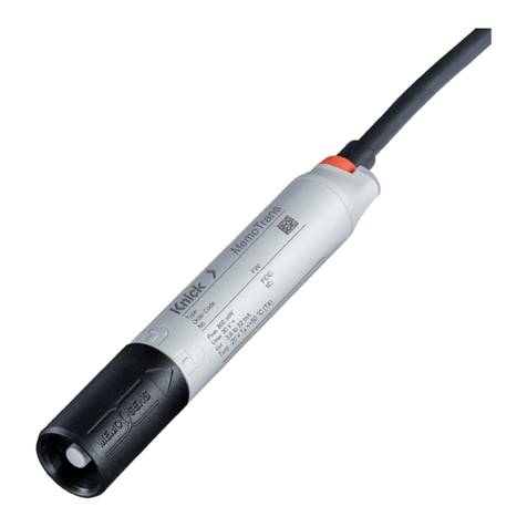
Knick MemoTrans User manual

User Manual
MemoTrans
Compact multiparameter
transmitter
www.knick.de
Read before installation.
Keep for future use.

MemoTrans
2
Supplemental Directives
READ AND SAVE THIS DOCUMENT FOR FUTURE REFERENCE. BEFORE ATTEMPTING TO ASSEMBLE, INSTALL,
OPERATE OR MAINTAIN THE PRODUCT, PLEASE ENSURE A COMPLETE UNDERSTANDING OF THE INSTRUC-
TIONS AND RISKS DESCRIBED HEREIN. ALWAYS OBSERVE ALL SAFETY INFORMATION. FAILURE TO COMPLY
WITH INSTRUCTIONS IN THIS DOCUMENT COULD RESULT IN SERIOUS INJURY AND/OR PROPERTY DAMAGE.
THIS DOCUMENT IS SUBJECT TO CHANGE WITHOUT NOTICE.
These supplemental directives explain how safety information is laid out in this document and what
content it covers.
Safety Chapter
This document's safety chapter is designed to give the reader a basic understanding of safety. It illus-
trates general hazards and gives strategies on how to avoid them.
Warnings
This document uses the following warnings to indicate hazardous situations:
Symbol Category Meaning Remark
WARNING Designates a situation that can lead to death or serious
(irreversible) injury.
The warnings contain
information on how to
avoid the hazard.
CAUTION Designates a situation that can lead to slight or moderate
(reversible) injury.
None NOTICE Designates a situation that can lead to property or
environmental damage.
Symbols Used in this Document
Symbol Meaning
Reference to additional information
Interim or final result in instructions for action
Sequence of figures attached to an instruction for action
Item number in a figure
Item number in text

MemoTrans
3
Table of Contents
1 Basic Safety Instructions.............................................................................................................. 5
1.1 Personnel Requirements.................................................................................................................................... 5
1.2 Intended Use.......................................................................................................................................................... 5
1.3 Symbols and Markings on the Product ........................................................................................................ 5
1.4 Occupational Safety ............................................................................................................................................ 5
1.5 Operational Safety ............................................................................................................................................... 6
2 Product Description ..................................................................................................................... 7
2.1 Product Design...................................................................................................................................................... 7
3 Incoming Acceptance and Product Identification ..................................................................... 8
3.1 Incoming Acceptance......................................................................................................................................... 8
3.2 Product Identification......................................................................................................................................... 8
3.3 Package Contents................................................................................................................................................. 8
3.4 Certificates and Approvals................................................................................................................................ 8
4 Installation.................................................................................................................................... 9
4.1 Dimensions............................................................................................................................................................. 9
5 Electrical Connection ................................................................................................................... 10
5.1 Connection ............................................................................................................................................................. 10
5.2 Post-Connection Check...................................................................................................................................... 10
6 Operating Options ....................................................................................................................... 11
6.1 Overview of Operating Options...................................................................................................................... 11
6.2 Structure and Function of the Operating Menu ....................................................................................... 11
7 System Integration ....................................................................................................................... 12
7.1 Integrating the Compact Transmitter into the System........................................................................... 12
8 Commissioning............................................................................................................................. 13
8.1 Preparatory Steps................................................................................................................................................. 13
8.2 Function Check...................................................................................................................................................... 13
8.3 Date and Time........................................................................................................................................................ 15
8.4 Configuring the Measuring Device................................................................................................................ 15
8.5 Configuration Management............................................................................................................................. 22
9 Operation ...................................................................................................................................... 23
9.1 Reading Measured Values ................................................................................................................................. 23
9.2 Adapting the Measuring Device to the Process Conditions................................................................. 24
10 Calibration .................................................................................................................................... 25
10.1 pH Sensor ................................................................................................................................................................ 25
10.2 ORP Sensor.............................................................................................................................................................. 25
10.3 Combo Sensor (pH/ORP) ................................................................................................................................... 25
10.4 Conductivity Sensor ............................................................................................................................................ 25
10.5 Oxygen Sensor ...................................................................................................................................................... 25

MemoTrans
4
11 Diagnostics and Troubleshooting............................................................................................... 26
11.1 Diagnostic Information via LED....................................................................................................................... 26
11.2 Adapting the Diagnostic Information........................................................................................................... 26
11.3 Adapting Sensor Diagnostic Information.................................................................................................... 27
11.4 Simulation............................................................................................................................................................... 35
11.5 Diagnostic List ....................................................................................................................................................... 36
11.6 Event Logbook ...................................................................................................................................................... 46
11.7 Resetting the Measuring Device..................................................................................................................... 46
11.8 Device Information .............................................................................................................................................. 46
12 Maintenance ................................................................................................................................. 47
12.1 Remarks.................................................................................................................................................................... 47
12.2 Maintenance Tasks ............................................................................................................................................... 47
13 Repair ............................................................................................................................................ 48
13.1 General Notes ........................................................................................................................................................ 48
13.2 Return ....................................................................................................................................................................... 48
13.3 Disposal.................................................................................................................................................................... 48
14 Specifications................................................................................................................................ 49
15 Power Supply ................................................................................................................................ 52
Index.............................................................................................................................................. 53

MemoTrans
5
1 Basic Safety Instructions
1.1 Personnel Requirements
• Installation, commissioning, operation, and maintenance of the measuring system may be carried
out only by specially trained technical personnel.
• The technical personnel must be authorized by the system operator to carry out the specified
activities.
• The electrical connection may be performed only by a licensed electrician.
• The technical personnel must have read and understood this User Manual and must follow the
instructions contained therein.
• Faults at the measuring point may only be rectified by authorized and specially trained personnel.
Note: Repairs not described in the User Manual provided must be carried out only directly at the
manufacturer’s site or by the service organization.
1.2 Intended Use
The device is a transmitter for connecting digital sensors with Memosens technology. It is preset for
sensor parameters and a measuring range span with 4…20 mA communication.
The device is designed for use in the following industries:
• Life science
• Chemistry
• Water and wastewater
• Food and beverage
• Power plants
• Other industrial applications
1.3 Symbols and Markings on the Product
CE marking
Special conditions and the product’s possible danger points. Read the user manual, observe the
specifications, and follow the instructions in the safety guide.
Reminder to read the documentation.
1.4 Occupational Safety
As the user, you are responsible for complying with the following safety conditions:
• Installation guidelines
• Local standards and regulations
• Regulations for explosion protection
Electromagnetic Compatibility
• The product has been tested for electromagnetic compatibility in accordance with the applicable
European standards for industrial applications.
• The electromagnetic compatibility indicated applies only to a product that has been connected in
accordance with this User Manual.

MemoTrans
6
1.5 Operational Safety
Before commissioning the entire measuring point:
01. Verify that all connections are correct.
02. Ensure that electrical cables and hose connections are undamaged.
03. Do not operate damaged products, and protect them against unintentional operation.
04. Label damaged products as defective.
During operation:
• If faults cannot be rectified: Products must be taken out of service and protected against
unintentional operation.
CAUTION! Cleaning not switched off during calibration or maintenance activities
Risk of injury due to medium or cleaning agent
• If a cleaning system is connected, switch it off before removing a sensor from the medium.
• If you wish to check the cleaning function and have therefore not switched off the cleaning
system, wear protective clothing, goggles, and gloves or take other appropriate measures.

MemoTrans
7
2 Product Description
2.1 Product Design
1
2
3
4
1Cable 3Memosens connection
2Housing 4LED, for optical signaling of operating statuses of measuring point
2.1.1 Measuring Parameters
The transmitter is designed for Memosens sensors with inductive connector:
• pH, ORP, pH/ORP combo sensors
• Contacting conductivity
• Oxygen, amperometric

MemoTrans
8
3 Incoming Acceptance and Product Identification
3.1 Incoming Acceptance
01. Verify that the packaging is undamaged.
✓Notify the supplier of any damage to the packaging. Keep the damaged packaging until the
issue has been resolved.
02. Verify that the contents are undamaged.
✓Notify the supplier of any damage to the delivery contents. Keep the damaged goods until the
issue has been resolved.
03. Check that the delivery is complete and nothing is missing.
✓Compare the shipping documents with your order.
04. Pack the product for storage and transportation in such a way that it is protected against impact
and moisture.
✓The original packaging offers the best protection. Make sure to comply with the permitted
ambient conditions.
If you have any questions, please contact your supplier or local sales center.
3.2 Product Identification
3.2.1 Nameplate
The nameplate contains the following information:
• Manufacturer identification
• Serial number
• Safety information and warnings
• Ex labeling on hazardous area versions
• Certificate information
Compare the data on the nameplate with your order.
3.3 Package Contents
The package contents include:
• 2-wire compact transmitter
• Installation Guide
If you have any questions, please contact your supplier or local sales center.
3.4 Certificates and Approvals
3.4.1 CE Mark
The product meets the requirements of the harmonized European standards. As such, it complies
with the legal specifications of the EU directives. The manufacturer confirms successful testing of
the product by affixing to it the CE mark.

MemoTrans
9
4 Installation
4.1 Dimensions
Note: All dimensions are given in millimeters [inches].

MemoTrans
10
5 Electrical Connection
WARNING! Device is live Incorrect connection may result in injury or death.
• The electrical connection may be performed only by a licensed electrician.
• The licensed electrician must have read and understood this User Manual and must follow the
instructions contained therein.
• Prior to commencing connection work, ensure that no voltage is present on any cable.
5.1 Connection
Supply voltage 12,6…30VDC (with a fault current >20mA)
14…30VDC (with a fault current set to 3.6mA)
Cable length 3m (10ft)
7m (23ft)
15m (46ft)
Signal output 4…20mA HART
Signal on alarm 3.6 or 23mA
1
2
1BU + 2WH -
Pull the previously cut insulation piece off the shielding braid and ground the braid appropriately.
The grounding cable is not a part of the package contents and must be provided by the customer.
• Connect ferrules as specified in the table:
Cable Function
Blue (BU) 4…20mA+
White (WH) 4…20mA-
5.2 Post-Connection Check
WARNING! Connection errors. The safety of people and of the measuring point is endangered.
The manufacturer does not accept any responsibility for errors that result from failure to comply with
the instructions in this manual.
Put the device into operation only if you can answer yes to all the following questions.
Electrical connection:
• Is the device or cable undamaged (visual inspection)?
• Do the mounted cables have adequate strain relief?
• Are the cables routed without loops or crossovers?
• Does the supply voltage match the specifications on the nameplate?
• No reverse polarity, is terminal assignment correct?

MemoTrans
11
6 Operating Options
6.1 Overview of Operating Options
Operation and settings via:
• PLC control station (via HART)
6.2 Structure and Function of the Operating Menu
In the Home view, the current measured values are displayed along with the device information (tag,
serial number, firmware version, order code).
The device is operated via four main menus:
• Guidance
• Diagnostics
• Application
• System
Menu Function
Guidance Contains functions involving a self-contained sequence of activities, e.g., for calibration
(= wizard).
Diagnostics Contains information regarding operation, diagnostics, and troubleshooting, as well as
configuration of the diagnostic behavior.
Application Sensor data for specific optimization and for detailed process adjustment. Adjustment of
measuring point to the application.
System These menus contain parameters for configuring the overall system.

MemoTrans
12
7 System Integration
7.1 Integrating the Compact Transmitter into the System
For measured value transmission:
• 4…20mA
• HART
7.1.1 HART
In addition to the analog 4…20mA signal, further measured values and the status of the device can
be transmitted digitally via the HART protocol.
Parameter setting is also possible using an additional control unit and a suitable driver.
Operation is possible via various operating devices (handhelds).

MemoTrans
13
8 Commissioning
1
2
3
45
6
1PLC (programmable logic controller) 4Sensor
2Junction box 5Option: HART control unit
3MemoTrans 6Digital panel meter
8.1 Preparatory Steps
01. Connect the device.
✓The device starts up and transmits the measured value as a current value.
8.2 Function Check
WARNING! Incorrect connection, incorrect supply voltage
Safety risks for staff and device malfunctions!
• Check that all connections have been established correctly in accordance with the wiring diagram.
• Ensure that the supply voltage matches the voltage indicated on the nameplate.
Familiarize yourself with the operation of the device before it is first switched on. In particular, please
read the “Basic Safety Instructions” chapter. After power-on, the device performs a self-test and then
goes to the measuring mode.

MemoTrans
14
8.2.1 LED Display
LED messages signal the status of the device and sensor.
LED behavior Status
Green
Blinks quickly
Everything OK.
Device starting up.
Green
Blinks twice
Everything OK.
Read out Memosens sensor information from sensor to transmitter (sensor type,
calibration data, etc.)
Green
Blinks slowly
Everything OK.
Sensor and device OK and functioning correctly.
Green
Blinks quickly three times
Everything OK.
Measured value at PLC in automatic HOLD.
If the “Sensor replacement alarm delay” is exceeded, the device transmits a signal on
alarm.
The automatic hold is set to 30 seconds but can be configured to suit the customer’s
needs.
Red
Blinks quickly
Failure of device or sensor
Error status signal as per NAMUR NE107.
Red, green
Blinks three times red
alternating with three times
green
Squawk
Squawk is signaled briefly while the connection is established. This makes it possible to
locate the device more quickly, e.g., when several devices are installed, you can see
which one the connection is established with.

MemoTrans
15
8.3 Date and Time
Configure the date and time in System Date Time .
Note: The date and time function runs only while the device is supplied with power. They must be
reset if the power supply is interrupted.
8.4 Configuring the Measuring Device
Path: Application Units
Function Options Info
Temperature unit Selection
• °C
• °F
• K
Factory setting
• °C
Conductivity unit Selection
• µS/cm
• mS/cm
• S/cm
• µS/m
• mS/m
• S/m
Factory setting
mS/cm
To be selected for conductivity.
Concentration (liquid) unit Selection
• mg/l
• µg/l
• ppm
• ppb
To be selected for oxygen.
Concentration (gaseous) unit Selection
• %vol
• ppm-Vol
8.4.1 Changing the Tag Number
You can change the tag number here:
System Device Management Tag Number

MemoTrans
16
8.4.2 Configuring the Sensor
Path: Application
Function Options Info
Sensor Sensor-dependent settings
Sensor type Display the sensor type
Order code Order code of sensor
ORP Display % value Display ORP as percentage
(pH/ORP combo sensors only)
Damping The damping causes a floating
average curve of the measured
values over the time specified.
Damping pH,
Damping ORP,
Damping oxygen,
Damping conductivity
0…60s
Factory setting
0 s
These functions determine the
damping of the primary value of
the connected sensor.
Damping temperature 0…60s
Factory setting
0 s
These functions determine the
damping of the integrated
temperature sensor.
TAG control
Sensor check Selection
• Off
• TAG
• Group
Factory setting
Off
Group Range: 0…65535
Extended setup
Conductivity:
Current cell
constant
Read only Value currently saved in the sensor.
Compensation Selection
• None
• Linear
• NaCl (IEC 746-3)
• Water ISO7888 (20°C)
• Water ISO7888 (25°C)
• Ultrapure water (NaCl)
• Ultrapure water (HCl)
Factory setting
Linear
Various methods are available to
compensate for the temperature
dependency.
Depending on your process, decide
which type of compensation you
want to use.
Alternatively, you can also select
None and thus measure
uncompensated conductivity.
Compensation for ultrapure water is
only available with contacting
sensors.
Meas. ref. temp. -5.0…100.0°C
(23.0…212.0°F)
Factory setting
25.0°C (77.0°F)
Reference temperature for calculating
the temperature-compensated
conductivity
Factor alpha 0.000…20.000%/K
Factory setting
2.100%/K
Enter the conductivity coefficient of
your process medium

MemoTrans
17
pH:
Temp. compensation Selection
• Off
• Automatic
• Manual
Factory setting
Automatic
Decide how you want to compensate the medium temperature:
• Automatically using the temperature sensor of your sensor
(ATC)
• Manually by entering the medium temperature
• Not at all
Medium comp. Selection
• Off
• Two-point calibration
Factory setting
Off
Take a sample from the medium and determine its pH value at
different temperatures in the lab.
Offset -18.00…18.00 pH
-100…100 mg/l
Factory setting
0.00 pH
0.00 mg/l
The offset compensates for a difference between a laboratory
measurement and an online measurement which is caused by
interference ions. Enter this value manually. If you are using a
compensation electrode, keep the offset at zero.
Internal buffer pH 0…14
Factory setting
pH 7.00
Only change the value if you are using a sensor with an internal
buffer other than pH7.
Oxygen:
Medium pressure Selection
• Process pressure
• Air pressure
• Altitude
Factory setting
Air pressure
Press Measured value to connect a pressure measured value via a
fieldbus input or a current input. This measured value is then
used for medium pressure compensation.
For the other types of compensation, specify a compensation
value for the measurement in each case.
• Specify either the altitude (‑300…4000m), the process
pressure (500…9999hPa), or the air pressure (500…1200hPa)
of the measuring point.
The pressure used during the calibration is also displayed for
information purposes. You can change this pressure in:
Calibration settings Ambient conditions Medium pressure
Salinity Selection
• Fixed value
• Measured value
Factory setting
Fixed value (0.0g/kg)
Diagnostic settings Sensor diagnostic settings
➜Adapting Sensor Diagnostic Information, p. 27

MemoTrans
18
Calibration Settings
Path: Application Sensor Calibration settings
Function Options Info
pH, ORP, pH/ORP, ISFET
Stability criterion Once the stability criterion is met, the measured value
is displayed in mV.
Delta mV 1…10mV
Factory setting
1 mV
Measured value depending on connected sensor
Duration 10…60s
Factory setting
20 s
Temp. compensation
(pH only)
Selection
• Off
• Automatic
• Manual
Factory setting
Fixed
Decide how you want to compensate the buffer
temperature:
• Automatically using the temperature sensor of your
sensor (ATC).
• Manually by entering the medium temperature.
Buffer recognition Selection
• Fixed
• Automatic (pH or pH/ORP
combo sensor only)
Manual
Factory setting
Fixed: You choose values from a list. The list depends
on the setting for Buffer manufacturer .
Automatic: The device recognizes the buffer automati-
cally. The recognition depends on the setting for
Buffer manufacturer .
NOTICE! As their zero point is offset, enamel pH sensors
cannot be calibrated and adjusted with automatic
buffer recognition.
Manual: You enter any two buffer values. These must
differ in terms of their pH value.
Buffer manufacturer Selection
• Endress+Hauser
• Ingold/Mettler
• DIN19266
• DIN19267
• Merck/Riedel
• Hamilton
Factory setting
Endress+Hauser
Temperature tables are stored internally in the unit for
the following pH values:
Endress+Hauser
2.00 / 4.00 / 7.00 / (9.00) / 9.22 / 10.00 / 12.00
Ingold/Mettler
2.00 / 4.01 / 7.00 / 9.21
DIN19266
1.68 / 4.01 / 6.86 / 9.18
DIN19267
1.09 / 4.65 / 6.79 / 9.23 / 12.75
Merck/Riedel
2.00 / 4.01 / 6.98 / 8.95 / 12.00
Hamilton
1.09 / 1.68 / 2.00 / 3.06 / 4.01 / 5.00 / 6.00 / 7.00 / 8.00 /
9.21 / 10.01 / 11.00 / 12.00
Calibration buffer 1…2The possible options and the factory setting depend
on the Buffer manufacturer .

MemoTrans
19
Function Options Info
Oxygen:
Stability criteria
Delta signal 0.1…2.0%
Factory setting
0.2 %
Permitted measured value fluctuation during
calibration.
Referenced to the raw value in nA in the case of
amperometric sensors.
Delta temperature 0.10…2.00K
Factory setting
0.50 K
Permitted thermal fluctuation during calibration.
Duration 5…60s
Factory setting
20 s
Timeframe within which the permitted measured value
variation may not be exceeded
Ambient conditions
Medium pressure Selection
• Process pressure
• Air pressure
• Altitude
• As during measurement
(measured value)
Factory setting
Air pressure1013bar
Process pressure
Medium pressure =
process pressure
500…1200hPa
Factory setting
1013 hPa
Enter the altitude or the average air pressure of the
place of calibration (mutually dependent values).
If you specify the altitude, the average air pressure is
calculated from the barometric altitude formula and
vice versa.
If you are compensating using the process pressure,
enter the pressure in your calibration medium here.
The pressure is then independent of the altitude.
Air pressure
Medium pressure =
air pressure
500…1200hPa
Factory setting
1013 hPa
Altitude
Medium pressure =
altitude
-300…4000m
Factory setting
0 m
Rel. hum. (air variable) 0…100%
Calibration monitoring
(calibration timer)
Function Selection
• Off (during operation,
during sensor connection)
Factory setting
Off
Calibration check:
calibration validity
The function checks whether the calibration of a sensor
is still valid. Example: You install a precalibrated sensor.
The function checks how long ago the sensor was last
calibrated. A diagnostics message is displayed if the
time since the last calibration is longer than specified
by the predefined warning and alarm limit.

MemoTrans
20
Function Options Info
Warning limit 1…20,000h
Factory setting
800 h
Warning and alarm limits mutually influence each
other's possible adjustable range.
Alarm limit 1…20,000h
Factory setting
1000 h
Warning and alarm limits mutually influence each
other's possible adjustable range.
8.4.3 Current Output
Path: Application Current output
Function Options Info
Current output
Output value pH, ISFET, ORP, and pH/ORP
options
• pH
• Raw value pH
• Impedance glass
• Impedance reference
• rH
• ISFET leakage current
• ORP mV
• ORP %
• Temperature
Oxygen options
• Partial pressure
• % saturation
• Conc. (liquid) unit
• Conc. (gaseous) unit
• Raw value nA
• Temperature
Conductivity options
• Conductivity
• Resistance
• Raw value (cond. uncomp.)
• Temperature
Depending on connected sensor
Range lower value (4 mA) The unit depends on the
sensor configured.
Enter the measuring range. The lower and upper range
values are assigned to the 4 mA value and the 20 mA
value respectively. The system uses the engineering
unit which you entered beforehand.
Range upper value (20 mA)
8.4.4 HART
Path: Application HART Output status
Function Options Info
Bus address 0…63
Factory setting
0
Enter the bus address
Address 0…63 Multidrop mode
PV value Choose from
Current output Output value
Primary process value
Partial pressure Partial pressure dependence for oxygen
Table of contents
Other Knick Transmitter manuals

Knick
Knick SensoTrans A 20220P0 Series User manual

Knick
Knick VariTrans P 42000 D2 TRMS-0001-KTA User manual

Knick
Knick MemoTrans MT 201N User manual

Knick
Knick PolyTrans P 32000 P0 Series User manual

Knick
Knick VariTrans P 41000 TRMS User manual

Knick
Knick SensoTrans R A 20230P0 Series User manual

Knick
Knick Stratos Multi E461N User manual

Knick
Knick MemoTrans MT 201N User manual

Knick
Knick Stratos Multi E401N User manual

Knick
Knick Stratos Eco 2405 CondI User manual