MachineTools OPERATINGINSTRUCTIONS
3
1、Main application and feature
1.1 Application:
This machine is widely suitable for machinery processing. That is drilling、scrape、
ream and tapping. Under certain conditions, it also can boring hole.
1.2 Feature:
1. Appearance is bounteous. The total layout is proportional。
2 Mechanical speed change which easily operation。
3.The surface of guide takes the quench treatment, which prolong the longevity of
machine’s operation.
4.There are a set of safety defense system 。
5.The electric system is reliable. It must according to relevant stipulate. 6.Reliable
Structure, good manufacture and high precision.
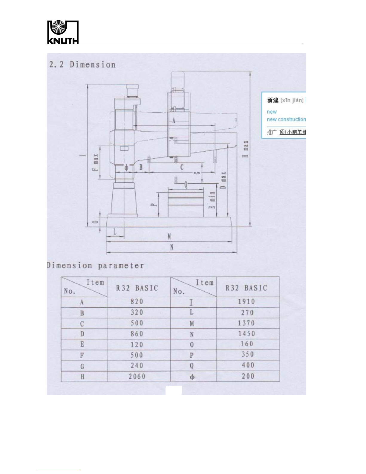
2、Main parameter and dimension
2.1 Main parameter
Max. drilling diameter:32mm
Tape:MT4
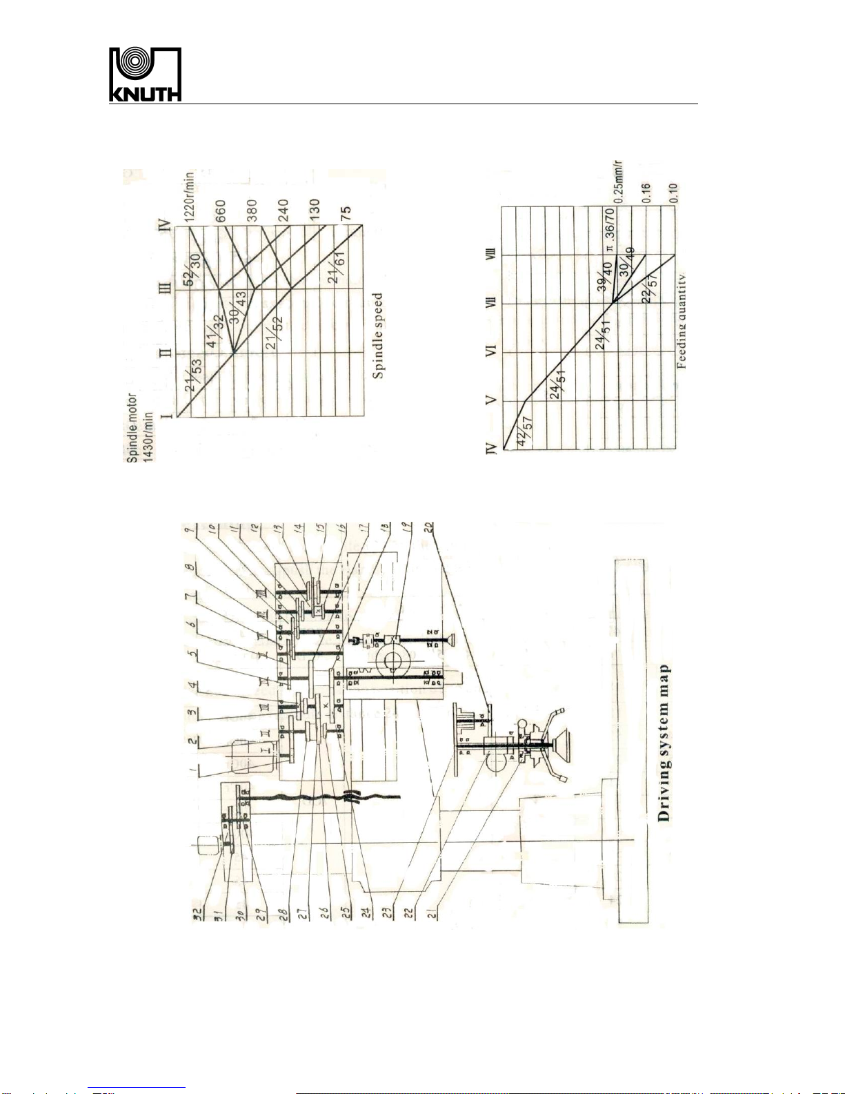
Number of spindle speeds:6
Range of spindle speeds:75~1220 r/min
Number of spindle feeding:3
Range of spindle feeding:0.10~0.25 mm/r
Speed of arm elevating:1.21m/min
Angle of arm:360°
Max. distance of spindle:200 Nm
Max. feeding power of spindle allowed:6300 N
Main motor power:1.5 KW
Arm elevating motor power:0.55 KW
Cooling motor power:0.09 KW
Weight:1200 Kg